 - WFG production - duplicate")


Title Page
-
Site conducted
-
Date of Assessment
-
Evaluation by
-
Site Representative
-
Location
-
Completed
-
Site Meeting Held today in conjunction with this report ?
-
Report Revision no:
-
Submission
-
Signed:
1. Scope
1.1 Purpose
-
The purpose of this Standard is to minimize the risk of personal injury by providing minimum requirements for the design, construction, installation, inspection, and maintenance of the mechanical refrigeration systems and volatile direct refrigeration systems specified in Clauses 1.2.1 and 1.2.2.
Note: This Standard does not directly address protection of property and preservation of the environment.
1.2 Application
-
1.2.1 Except as specified in Clause 1.2.3, this Standard applies to the design, construction, installation, inspection, and maintenance of every refrigeration system as provided for by the Act (as defined in Clause 3) and identified in this Standard.
-
1.2.2 This Standard applies to:
a) all refrigeration systems installed subsequent to its adoption. This includes refrigeration systems installed in a new or existing premises. It also applies to all premises, including the machinery room if required, in which a refrigeration system is to be installed;
b) refrigeration systems that undergo a substitution of refrigerant in a premises defined in Item a); and
c) those parts of a refrigeration system that are replaced in, or added to, systems installed prior to its adoption.
Note: When adding or replacing parts [see Item c)], consideration should be given to the premises requirements of Item a). -
1.2.3 This Standard does not apply to the following:
a) the use of water or air as a refrigerant;
b) bulk-storage gas tanks not permanently connected to a refrigeration system;
c) refrigeration systems installed on railroad cars, motor vehicles, motor-drawn vehicles, aircraft, or ships; and
d) refrigeration systems used for air conditioning in private residences.
2 Reference Publications (Administrative only)
-
Nothing to input from code
3 Definitions & Abbreviations (Admin only)
-
Nothing to input from code
4. System selection and application requirements
-
4.2 Classification occupancy
-
4.3 Classification of refrigeration system
-
4.3.1.2 Direct System
-
4.2.1.2.2 Double Direct System
-
4.3.1.2.3 Volatile Direct system (pumped Co2) with evaporator
-
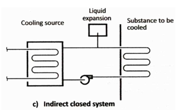
Typical Rink Installation (INDIRECT CLOSED)
-
4.2.1.3 Indirect system – An indirect system is one in which a secondary coolant that is cooled or heated by a refrigeration system I circulated to the air or other substances to be cooled or heated. Indirect systems are distinguished by the method of application as follows:
a) An indirect open spray systems are one in which secondary coolant is in direct contact with the air to be heated or cooled
b) A double Indirect open spray system is one in which the secondary substance for an indirect open spay systems described in item, a) is heated or cooled by a secondary coolant circuited from a second enclosure
c) An indirect closed system is one in which a secondary coolant passes through a closed circuit in the air or other substance to be cooled to heated
d) An indirect closed system is one in which a secondary coolant passes through a closed circuit (chiller) in the air or other substance (brine) to be cooled or heated [see figure 4.c.] -
-
4.3.2 Classification by leakage probability
-
This installation is of a primary refrigerant classified as:
-
Reg 4.4.1 (Table 1- page 28)
4.4 Classification by refrigerant
4.4.1 ASHRAE 34 classification of refrigerants
For the purpose of this review:
• Ammonia is a B2L, single fluid refrigerant.
• Co2 is and A1 Refrigerant & R-404a is an A1 refrigerant.
• R-22 is an A1 refrigerant. -
Table 2 - System Application Requirements by Leakage probability is found to be
-
4.6 Additional requirements for institutional, public assembly, residential and commercial occupancies
-
4.6.1. .. No portion of the systems shall be installed in or on a public stairway, landing, or exit.
-
4.6.2 …No portion of the systems shall interfere with free passage through a public hallway or lobby.
5. Equipment Design and construction
-
5.1 Drawings, specifications and Data reports
The design, construction, testing and stamping of every pressure vessel and its associated piping , as well as the registration of fittings, shall comply with CSA B51
- namely CSA B51- Section 9 - Refrigeration equipment
The design, construction, installation, inspection testing and repair of refrigeration equipment shall meet the requirements of CSA B52. -
5.1.2 Design drawings and specifications for all vessels and pertinent safety devices shall be submitted to the regulatory authority for acceptance and registration before construction.
-
5.1.3 A data report covering each vessel, constructed in accordance with the accepted and registered design shall be submitted to the regulatory authority by the manufacturer via the installing contractor.
-
5.2 Refrigeration systems (including piping and all categories of fittings and excluding pressure vessels) may be except from the registration, provided that the following conditions are met:
-
a.) the refrigeration system has a prime mover nameplate rating of less than 125kW (167 HP) or less. If more than one system is installed in a single location,
-
i.) the systems are independent of each other and not connected with a common header or other means such that a failure of one system will not impact on than other systems or
-
ii.) if the systems are interconnected, the total of the prime movers added together does not exceed 125kW (167 HP); and
-
b.) the refrigeration system is covered by the following standards and is tested and certified by an approved testing laboratory. CAN/CSA-C22.2 No. 60335-2-24; ii.) CAN/CSA-C22.2 No. 60335-2-40; iii.) CAN/CSA-C22.2 No. 60335-2-89 or CSA C22-2 No. 120 or No. 128. (ala LISTED equipment)
-
All other provisions of the standard shall be complied with, including the total quantity of refrigerant, per occupied space as provided in Table 1. Occupancy classification and the use of a machinery room.
-
What is estimated / noted charge of the system?
-
5.9.1 All systems shall have provisions for safely handling refrigerant charge for servicing purposes without venting the charge to atmosphere.
-
5.9.3.1. All systems having more than 110 pounds (50kg.) of refrigerant shall have stop valves installed at the following locations: in/out of each compressor; liquid pumps, CU; in/out of separator/ receiver; suction/discharge or CU; in/out of condenser; evaporator(s)
-
5.9.5 Stop Valves shall be suitably labelled, numbers may be used to label the valves, provide a key to numbers located near the valves
-
5.10.4.5 - Dated Declaration of (pressure) test signed by the installer shall be provided for systems containing more than 23kg (50pounds) or more of refrigerant. Declaration shall state name of gas, field test pressures applied to hi and low sides of systems and duration of test.
-
5.11 Marking and labelling
-
5.11.1 Signs (all systems) shall include name and address of installer, refrigerant type, lubricant and amount, total weight of the refrigerant required for normal ops, field test pressure applied, system refrigeration capacity and normal conditions and ratings for prime movers, in kW (HP) and FLA and voltage.
-
5.11.3 Signs for systems containing more than 45kg (100 pounds) of refrigerant … supply and mount durable signs with letter not less than 13 mm (1/2in) high designating at minimum the main disconnect switches), any remote-control device(es), pressure limiting devices, each pressure vessel and main shutoff to each vessel and the refrigerant piping (indicating whether it is at the high-side or low-side pressure and whether it is normally in the LIQUID or VAPOR state
-
5.11.4 New signs for changed refrigerant - shall be compliant with clause 5.11.1
-
5.11.5 Posting of instructions It is the duty of the owner of a refrigerating system with prime movers having a capacity exceeding 125kW (175hp) to place in a conspicuous location and as near as practicable to the refrigerant compressor(s) a card giving directions for operating the systems, including precautions to be observed in case of breakdown or leakage as follows:<br>a) telephone number of first response organization for emergency<br>b) instructions for shutting down in case of emergency<br>c) name, address, phone, day and night phone for service provider and<br>d) name, address, night and day phone for nearest AHJ and instructions to notify the authority in emergency situations<br>NOTE: A safety procedure for Emergency Evacuation and Preparedness Plan shall be considered onsite.
-
NOTE: consideration should be given to preparing an emergency evacuation plan for those installations for which a plan is appropriate
6. Installation
-
General Installation of the System(s)
-
6.1.1 Foundations and supports for condenser and condensing units and compressor units shall be structurally sound and non-combustible.
-
6.1.3 Safe inspection and maintenance of systems shall allow for proper clearance for floor mounted equipment. Roof and mezzanine mounted shall have fall arrest and railings and equipment shall be set-back from edge (10feet min.) from any edge with rails as per local OSHA and WHS requirements shall apply. (CLC section 12.06 https://laws-lois.justice.gc.ca/eng/regulations/sor-86-304/fulltext.html)
-
Access Ladders, safety cage, service platform noted around condenser(s) and other roof mounted equipment requiring weekly/monthly/ annual servicing.
-
6.2 Machinery rooms
-
6.2.1 General – machinery room shall provide adequate access and clearance for service and maintenance to all equipment and for replacement.
-
6.2.2 Doors – all doors shall be outward opening, self-closing, tight fitting and large enough that persons can escape in an emergency. Doors shall not open into a public corridor or any room used for assembly, as well no leakage of gas from the room shall be permitted to escape into other parts of the building.
-
Panic hardware shall be on all doors opening outward from the machine room space.
-
6.2.3 Refrigerant Vapor detector – for all refrigerants but for ammonia R717 (see Clause 6.3 Class T rooms) Sensors shall be located in an area where the refrigerant leak is most likely to occur and concentrate and shall be actuated at a value greater than the OEL (or consistent toxicity measure) and shall<br>a) sound an audible alarm and<br>b) initiate mechanical ventilation system; as per clause 6.2.5.5 ventilation design and operations.
-
NOTE: in some cases more than one (1) sensor may be required
-
This Auditors suggestion for multiple sensor(s) and external to the room PPM readouts to determine levels prior to entering the room
-
6.2.4.1 No open flames or apparatus to produce an open flame shall be installed in a machinery room where refrigerant other than Co2 is used.
-
6.2.4.3. Combustion equipment may be installed in the same machinery room under one of the following conditions:
-
6.2.5 Ventilation
6.2.5.5 Mechanical ventilation system shall operate capable of removing air from the machinery room at a rate of not less than calculated as follows: -
Note: Also see IIAR Ventilation excel spreadsheet calculator for IIAR ventilation calculated results for comparison.
-
6.2.5.3 Air inlets to exhaust system shall be located near machinery, suitable guarded and at an elevation where refrigerant leak is most likely. Provisions to be made for outdoor makeup air to replace exhaust. Openings for makeup and to be positioned to avoid intake of exhaust air. Air shall be discharged in a manner that does not cause inconvenience or danger. ASHRAE 62 requires min. 25 feet from building openings. Air supply to machinery room shall serve NO other area of the building.
-
6.2.5.5 Leaks or ruptures calculation
-
Q = 100 x √(G) where <br>Q is airflow in CFM and G – mass of refrigerant in pounds, (For systems containing less than 15, 400 pounds gas total)
-
6.2.5.5.2 Minimum Ventilation<br>Whenever the refrigeration system is operating or whenever the room is occupied, a sufficient part of the mechanical ventilation shall be operable to provide normal volumes equal to the greater of the following:<br>a) 0.5 cfm/sq.ft of machinery room are; or<br>b) Volume required to prevent a maximum temperature rise above ambient greater that 18dF, based on all of the heat producing machinery in the room.<br>
-
6.2.5.7 Minimum temperature – supplemental heat to maintain machinery room temperature of 40 ̊F where damage could result at temperature below freezing. Heaters shall not be flame producing as per item 6.2.4.1 above
-
6.2.5.8 Air to and from an occupied space- the passage of air to and from an occupied space through machinery room shall be permitted only when the air is ducted and sealed in a manner that prevents any leakage of refrigeration from entering the airstream. Access doors and panels in ductwork and air handler units shall be gasketed and tight fitting.
-
As specified in cases with use of Ammonia as primary refrigerant, Class T machine room shall meet the following special requirements:
-
6.3 MACHINERY CLASS T ROOM
-
a) There shall be no flame-producing device or hot surface over 427 °C (800°F) permanently installed in the room.
-
b) The room shall have at least one exit door that opens directly to the outer air. Other exits communicating with the building shall be permitted, but shall be through a vestibule equipped with approved self-closing, tight-fitting fire doors.
-
c) The machinery room envelope, including any vestibule, shall be of tight construction.
-
Is there a vestibule from room to opccupied areas of the building meeting Class T Code requirements?
-
d) The machinery room walls, floor, and ceiling shall be of non-combustible construction. Walls, floors, and ceiling separating the machinery room from other occupied spaces shall have a rating of at least one-hour fire-resistive construction.
-
Note: The requirements in this Clause are over and above the requirements specified in the National Building Code of Canada or the building code in use by a province or territory.
-
e) Exterior openings, if present, shall not be under any fire escape or any open stairway.
-
f) All pipes piercing the interior walls, ceiling, or floor of a Class T machinery room shall be tightly sealed to the walls, ceiling, or floor through which they pass.
-
g) Air ducts passing through a Class T machinery room shall be of tight construction and shall have no openings in such rooms.
-
h) Remote pilot control of the mechanical equipment in the machinery room shall be located immediately outside the machinery room and shall be provided solely for shutting down the equipment in an emergency. Ventilation fans shall have a control switch on a separate circuit located immediately outside of the machinery room, and shall be permitted to run as long as power is available
-
i) An independent mechanical ventilation system shall be provided as specified in Clause 6.2.5.5. In basements, the ventilation system shall be operated continuously. All locations shall be equipped with a vapour detector that shall automatically start the ventilation system and actuate an alarm at the lowest practical detection levels not exceeding the concentration limits specified in Item c) iii) of Clause 4.5.2 or 300 ppm for ammonia. The vapour detector shall also initiate a supervised alarm so that corrective action can be initiated.
-
j) When refrigerants of Groups A2, A3, B2, and B3 are used, the machinery room shall conform to the requirements for Zone 2 locations as defined in the Canadian Electrical Code, Part I. (Electrical Design Input Req'd)
-
Note: Ammonia is excluded from the requirements of this Clause (j)
-
Auditors suggestion for PPM readouts at ALL exits to machinery room
-
6.4.2 Machinery rooms – containing ammonia systems shall be considered Zone 2. Hazardous location and all electrical equipment in the room shall comply with the requirements for Zone 2 locations as defined in the Canadian electrical Code Part 1
-
6.5.2 Discharge water lines shall not be directly connected to waste or sewer systems. The waste or discharge from such equipment shall be through an accepted air gap or trap
-
6.8.1 Location of refrigerant piping, consideration shall be given to location to minimize the danger of being struck from falling object, material or service equipment handling or general traffic, should this be the case, protection will be required.
-
6.8.2 In any building , refrigerant piping crossing and open space that provide passage way shall not be less than 2.3M (7.5feet) above finished floor
-
6.8.3 Piping shall not be installed in enclosed stairway, stair landing or exit
-
6.8.5 Piping may be installed horizintally in closed floors or open joists spaces. Piping installed in concrete floors shall be encased in pipe duct, exception case that being ice rinks.
-
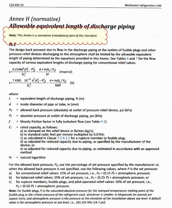
6.10 Emergency Discharge (Fire Line Venting) - An Emergency discharge system, shall be provided when mandated by the AHJ - ITS; otherwise, an emergency discharge systems shall not be required for a NEW or Existing system there the relief piping is in compliance with the current requirements of Annex H.
-
ANNEX H:
-
FOR AN EXISTING SYSTEM where the PRV (Pressure Relief Valve) venting lines are NOT in compliance with Annex H, consideration shall be given to the provision of an emergency discharge systems (per Annex B)
-
ANNEX B
-
This Engineer's Suggestion for installation and an Emergency Discharge piping system to be considered.
-
This System is considered as a NEW (existing) system or Retrofit System
7. Overpressure Protection
-
7.1.1 Pressure vessels shall be provided with Pressure-relief protection in accordance with rules specified in UG-125 to UG-134, Section VIII, Div.1 of ASME Boiler and Pressure Vessel Code.
-
7.1.2 Pressure vessels with volume equal or less than 0.085 M^3 (3 ft ^3) that can be isolated with valves must have relief device, vessels less that 152 mm (6” dia) are exempt
-
7.1.3.2 Vessels between internal volume 0.085 M^3 (3 ft”3) and 10 ft^3 may use a single relief device
-
7.1.3.3.2 Vessels with volume greater than 10 ft ^3 must use dual relief valves
-
7.1.4 Evaporators less than 6in dia shall be exempt from PRV requirements
-
7.2.2.3 Pressure limited devices shall be installed with no intervening stop valves between the pressure imposing element and any stop valve on the discharge side
-
7.2.3.1.1 When compressor has a stop valve on discharge side, it must have a pressure relief (in some jurisdiction it CAN NOT be an internal relief to the suction side as per local AHJ) utilizing a valve that is NOT affected by back pressure (upstream ) pressure of the low side (crankcase on compressor)
-
ITS Ruling Decemeber 23, 2004 (Peter Skrupski)
-
7.2.4 Consideration shall be given to possible expansion of refrigerant trapped between stop valves
-
7.3.6.1.1 Fusible plugs and other pressure relief devices shall discharge to the outside of the building on any given systems containing:
a) Group A2 or B3 refrigerant
b) More than 3kg (6.6lbs) of group A2, B1, B2
c) More than 50 kg (110 lbs) of group A1 gas -
7.3.6.1.2 Discharge to be not less than 4.6m (15ft.) from above adjoining ground level and not less than 7.6m (25ft.,) from any building opening
-
7.3.6.1.3 Ammonia Can be discharged into a Difussion Tank containing 8 kg of water for every kg of ammonia (8 pounds per pound Ammonia) that will be released in 1hr from largest relief
-
Sufficient vacuum breaker installed to prevent water intake at tank into system
-
Auditors Evaluation of PRV pressure relief system being in need of in-depth, critical and detailed review or significant alterations to meeting code.
-
Are PRV's installed on the Oil Separators of each compressor in accordance with ASME B31.5
8. Maintenance of Systems
-
8.1.1 General - a.) Only approved containers shall be used; b.) Only individuals satisfying local requirements are permitted to transfer refrigerants; c.)No service refrigerant containers shall be left connected to a system, except when a refrigerant is being charged or withdrawn. <br><br>See also 8.3 Refrigerant storage and containers approved, limited to 300 pounds
-
8.2.2 When secondary refrigerant and lubricants are withdrawn from a system, it must be drawn into an approved container and fluid shall be recycled, recovered, or disposed of as per applicable regulations of the local AHJ.
-
8.3 Refrigerant Storage - refrigerant in addition to that in the system, shall be stored only in and approved machinery room. Such Refrigerant shall not exceed 136kg (300pounds) and shall be stored in acceptable containers. Storage shall first be approved by AHJ AND be secured to the wall with chains or means of preventing tipping.
-
8.4.2 Minimum maintenance requirements shall apply to all refrigeration systems:
-
a) Pressure – relief valves (PRV’s) shall be replaced and or recertified every 5 five years
-
b) C02 systems PRV's only
-
c) Pressure limited devices shall be tested every 12 months (tags on unit)
-
d) Other safety devices shall be tested every 12 months for accuracy (tags on unit)
-
e) Permanent leak detectors shall be tests for function at the specified refrigerant concentration in accordance with manufacturers instructions. Maximum interval shall not exceed One (1) year. Leak detector in a simulated test shall initiate an audible alarm and visible alarm and begin emergency ventilation at rate noted in clause 6.2.5.5
-
f) All safety related maintenance recommendation by the equipment manufacturer and any and all instruction from service provider shall be followed and corrective action taken to relieve the issue
-
g) All power and control termination shall be checked every 12 months (tags on unit)
-
h) Periodic visual inspection in conjunction with operational system logging and pertaining characteristics shall be performed
-
i) Testing for leaks – periodically per regulations, as required my manufacture, when physical evidence shows, upon activation of a vapour detector alarm
-
j) Secondary refrigerant(hydronic) systems shall have
-
j.i) Testing for corrosion
-
Is there a Corrosion test Coupon Station installed?
-
j.ii) Flow rates set to prevent erosion
-
j.iii) Fluids with potential to solidify, specific gravity or refractive index verified to prevent equipment damage (Ie Brine)
-
At the end of each test a tag, noting the test date, testers name shall be affixed to the tested components specified in items a to j above. As required by ITS(MB) AHJ
-
8.4.4 Additional requirements:<br> a) Systems shall be kept clean<br> c) refrigerant quality shall meet acceptable values – no recycled gases
-
8.4.5 Equipment Logging
-
Brine sample testing shall advise of at minimum the freeze point, calcium chloride mixture %, Specific gravity, total dissolved solids (TDS) and the apparent levels of inhibitors such as Chromate, which shall not exceed 3-4 ppm (mg/dL)
NOTE: a test of all brine samples shall include testing for Chromate which is highly carcinogenic corrosion inhibitor. -
Equipment logging shall consist of the following
-
a) Systems shall be logged as per manufacturers requirements and suggestions. Logs and records shall consist of characteristics, environmental issues, and safety design criteria/ issues
-
b) Logs shall be manually or electronic and made available for local AHJ on request per regulations
-
c) Systems logs should be periodically compared with original startup log (minimum annually, preferable monthly) to compare efficiencies and safety conflicts)
9. Precautions
-
9.1.1 Owner of the systems shall supply and maintain for its employees the PPE personal protective equipment required by jurisdiction where system is located.
-
RAGAGEP - Staff shall have basic refrigeration training and system knowledge to perform tests and logs as required by code, prevailing power engineers act and be of sufficient trained levels per AHJ requirements.
-
Registered and certified training has been met
-
9.2 Enclosed spaces (freezer systems), crawlspaces, vessels, interstitial spaces & access hatches.
-
Enclosed spaces Signage missing?
10. RAGAGEP – General
-
Precautions must be taken to minimize piping damage from external corrosion in cases where pressure line are wrapped in insulation.
-
Avoid Armaflex piping insulation and fibreglass which causes the under-film to corrode. Therefore, corrosion resistance materials, a durable protective coating such as hot dipped galvanized, weather resistant paint or other suitable protection shall be applied first
-
CRN Numbers shall meet the required code(s) for the province in which registered vessels are installed, and if stamped with other jurisdiction CRN number must be re-evaluated by the local AHJ and approved prior to use
-
Full system piping and P&ID drawings of the systems shall be installed on the wall under protective or coated glass glass or plastic surface for review; complete with Valve tag listing and valve locations. As-built’s of the installation shall be stored onsite for use by staff and operators
-
Certified AHJ approved drawings shall be posted on wall of engine room. IOM’s (installation operator manuals shall be logged hardcopy or digital onsite for use by staff, operators and service technicians.
-
Guarded Status Panel and safety tests switches shall be installed regardless of tonnage system and whether it’s regulated as > 50-ton plant (per power engineers or not
-
Guarded status panel testing, valves, switches and control points shall be installed to meet general testing and logging requirements.
General Findings - Conditions - Costing Estimates
- Item
-
Room / Area
-
System / No. / Component
-
Condition as found
- Very Good
- Good
- Fair
- Poor
- Imminent Failure
- Inoperable / Failed
- N/A
-
Safety Concern(s)
- Safe
- Needs Attention
- At Risk
- N/A
-
Recommendation
-
Costing Implications (Class "D" Level) - Estimate
Completion
-
Prepared by
-
Completed
-
Site Meeting Held today in conjunction with this report ?
-
Site Observation Inspection Completed
-
Signed:
-
Distribution
-
Distribution - OTHER