


Title Page
-
TANK NO:
-
Site conducted
-
Location
-
Conducted on
Tank Description
General
-
Nameplate:
-
Where is it located
-
Design Std.:
-
Manufacturer:
-
Cathodic Protection:
-
Product:
-
Specific Gravity:
-
Normal Oper. Temp.:
-
Nom. Tank Pressure:
Dimension
-
Diameter:
-
Nom. Capacity:
-
Height:
-
Working Height:
Geometry
-
Foundation:
-
Bottom:
-
Shell:
-
Explain
-
Fixed Roof:
-
Explain
-
Floating Roof:
-
Primary Seal:
-
Secondary Seal:
Dates
-
Year Built:
-
Last Inspection Internal:
-
Last Inspection External:
-
Last Coated:
Access
-
Shell/Fixed Roof Access:
-
Floating Roof Access:
Coatings
-
Bottom: Internal:
-
Bottom: External:
-
Shell: Internal:
-
Shell:External:
-
Fixed Roof: Internal:
-
Fixed Roof: External:
-
Floating Roof: Internal
-
Floating Roof: External:
Tank Material Data Table
-
Shell Course 1 Material
-
Shell Course 2 Material
-
Shell Course 3 Material
-
Shell Course 4 Material
-
Shell Course 5 Material
-
Shell Course 6 Material
-
Shell Course 7 Material
-
Shell Course 8 Material
-
Bottom Plate Material
-
Annular Plates Material
-
Fixed Roof Plates Material
-
Floating Roof Plates Material
undefined
SUMMARY AND REPAIR RECOMMENDATIONS
-
The following is a summary of the significant findings of the inspection. (Item numbers correspond with item numbers on the API 653 Checklist). Note: Recommendations noted in this section are preliminary and may be subject to change pending Engineering calculations, as well as an Engineering review of the inspector's report.
-
INSPECTION SUMMARY
-
FOUNDATION:
-
BOTTOM:
-
SHELL:
-
NOZZLES AND APPURTENANCES:
-
FIXED ROOF:
-
FLOATING ROOF:
-
Other
1. Containment, Foundation and Fire Suppression
1.1.1 FOUNDATION SETTLEMENT EVALUATION
-
Perform MT or PT on welds at areas where settlement failed or where edge settlement is present. Acceptable / Ref. Summary / N/A
-
Perform Settlement survey of the tank. Acceptable / Ref. Summary / N/A
1.1.2 General
-
Check for signs of bottom leakage. Acceptable / Ref. Summary / N/A
-
Tank Bottom Release Prevention Systems. Acceptable / Ref. Summary / N/A
-
Inspect for excessive vegetation against bottom of tank. Acceptable / Ref. Summary / N/A
-
Inspect for cavities under foundation. Acceptable / Ref. Summary / N/A
1.1.3 Site Drainage
-
Check for presence of containment drains.
-
Verify if containment drains are clear and free of debris.
-
Check for evidence of standing water against tank.
-
Verify if surrounding grade allow water to drain away from the tank.
1.1.4 Tank Foundation
-
Inspect for broken concrete, spalling and cracks. (particular attention under back-up bars used in butt welded annular ring under the shell)
-
Note station location of deterioration
-
Check for presence of leak detection. Verify condition and no bottom leakage
-
Check whether the concrete ringwall allows rainwater to properly drain away
-
Verify condition of the foundation drip ring Acceptable / Ref. Summary / N/A (if applicable)
Asphalt Apron
-
Check for settling of tank into asphalt Acceptable / Ref. Summary
-
Inspect for broken, deteriorated or cracks in asphalt.
Earth
-
Check for settling of tank into ground / earth.
Grillage member
-
Grillage member details and orientation Spacing (center to center): Qty.: Inspect Grillage members for corrosion or distortion.
Anchorage
-
Verify if the tank anchors are API standard N/A Acceptable / Ref. Summary type. If not, detail type.
-
Inspect anchor bolt(s) or anchor strap(s) for distortion, indicating serious foundation settlement or tank overpressure uplift. Acceptable / Ref. Summary
-
Inspect nut(s) for a tightened snug fit, degradation of the anchor chair assembly Acceptable / Ref. Summary / N/A
-
Inspect anchor straps for degradation and concrete deterioration. Acceptable / Ref. Summary / N/A
-
Anchor Chair Dimension
-
Anchor Chair Detail & Dimensions
-
Qty:
-
Spacing (ft.)
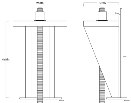
Anchorage
-
Repad? Yes No
-
Tell-Tale? Yes No
-
Repad Size: Width X Height X Depth
-
Bolt Size: Single Nut Double Nut
-
Single nut or Double nut
-
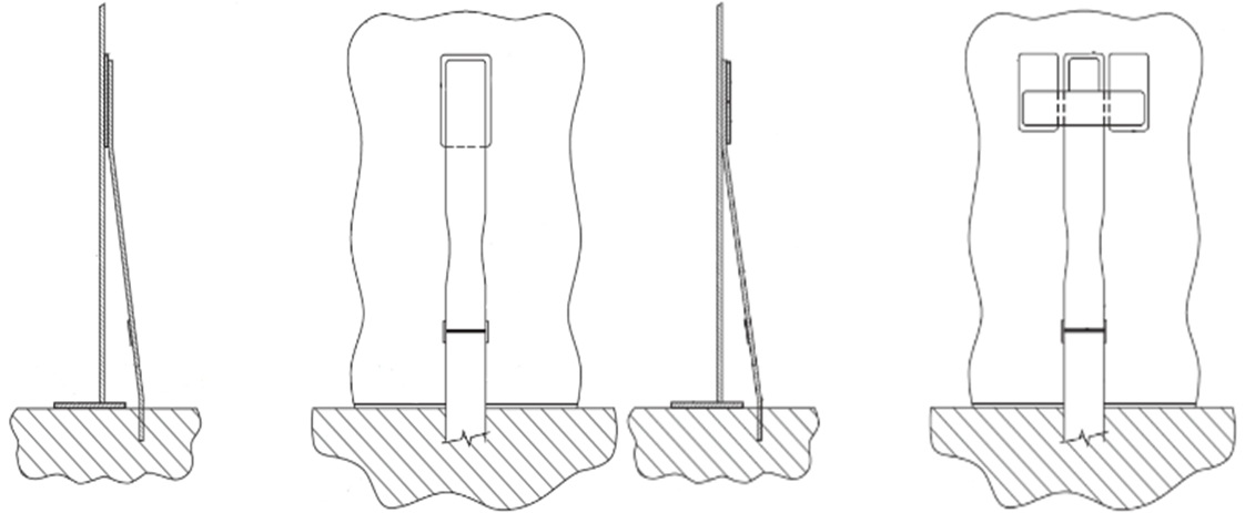
Anchor Strap Detail and Dimensions
-
Type: A or B
-
Qty:
-
Spacing (ft.)
-
Repad? Yes No
-
Tell-Tale? Yes No
-
Repad Size: Width Height
1.1.5 Fire Suppression System
-
Verify the condition of the fire suppressant system.
-
Check the overall condition of the foam
-
Open-top / EFR: Check the condition of the fire suppressant shell extensions for corrosion or defects
-
Inspect overall condition of deluge system and components (corrosion, missing or damaged parts, etc.)
FOUNDATION RECOMMENDATION PHOTOS
-
PHOTOS
-
DESCRIPTION
1.2 BOTTOM
1.2.1 Overview
-
Verify if tank is clean, gas free and safe for entry. The tank shall be isolated (product, steam, electrical, etc.) to prepare for entry.
-
Check for evidence of falling objects (roof rafters, large patches of scale, corroded through plates, etc.).
-
Complete a Floating Roof Checklist to determine that the floating roof is secured for confined space entry.
1.2.2 Bottom
-
Perform a visual inspection of the bottom plates. Document all findings and limitations (client must be notified of limitations while on site).
-
Visual inspect for bottom depressions, bulges, and edge settlement.
-
Perform Magnetic Flux Leakage (MFL) scan of tank bottom.
-
Document pit depth with pit type (sharp edged, lake type, general, scattered, etc.).
-
Collect and review bottom plate and critical zone UT (if applicable) per proposal.
-
Check for reinforcing plates under brackets, supports, gauge poles, etc. and perform a visual inspection.
-
Visually inspect floating roof leg striker plates for weld corrosion, pitting, cutting, or excessive dimpling.
-
Visually inspect for the presence and condition of previous repairs (patch plates, puddle welds, etc.).
-
Overall condition of the coating system (notate coating failure such as cracks, blistering, chalking, discoloration, rust blooms, adhesion failure, etc.).
-
Are recordable indications and defects identified on the bottom layout and logged in the bottom reduction form?
Bottom Welds
-
Perform a visual inspection of all lap/butt welds and internal shell-to-bottom weld. Document all findings and limitations (client must be notified of limitations while on site).
-
Vacuum Box Inspection of lap/butt welds
-
Magnetic Particle (MT) or Liquid Penetrant Inspection of lap/butt welds and/or internal shell-to-bottom weld.
Bottom Sump(s)
-
Perform a visual inspection of the sump(s). Document all findings and limitations (client must be informed of limitations while on site).
-
Document pit depth with pit type (sharp edged, lake type, general, scattered, etc.).
-
Collect and review bottom sump UT for significantly low reading(s).
-
Magnetic Particle (MT) or Liquid Penetrant (PT) Inspection of sump-to-bottom weld.
-
Magnetic Particle (MT) or Liquid Penetrant (PT) Inspection of sump welds.
-
Coating condition of the sump(s).
RECOMMENDATION PHOTOS
-
PHOTOS
-
DESCRIPTION
1.2.3 Bottom Edge Projection
-
Inspect bottom edge projection for corrosion. If corrosion is present, consideration must be given to the extent of which it extends under the shell and internal bottom.
-
Verify if soil or gravel are covering the bottom edge projection and/or the lower shell. If applicable, remove soil or gravel in areas for inspection. Detail findings and average depth of soil or gravel in summary.
-
Average depth of soil or gravel:
-
Check for inadequate plate projection away from the shell that is less than 3/8" in length and less than 0.100 thickness.
-
Overall condition of coating system (notate coating failure such as cracks, blistering, chalking, discoloration, rust blooms, adhesion failure, etc.).
-
Verify type and condition of bottom-to-foundation seal (moisture barrier), if applicable.
-
Does the tank have a single bottom or double bottom?
-
Distance between bottoms?
-
Verify the underside of the new bottom is welded, caulked, or neither.
-
Verify condition of dead shell material.
-
Check if drain ports are present between double bottom
-
Are valves in the closed position?
RECOMMENDATION PHOTOS
-
PHOTO
-
DESCRIPTION
1.3 Shell
1.3.1 Shell Plate
-
Are conditions present that would limit the inspection of the external shell? (Client Acceptable / Ref. Summary / N/A must be informed of limitations while on site)
-
Overall condition of coating system (notate coating failure such as cracks, blistering, chalking, discoloration, rust blooms, adhesion failure, etc.)
-
Collect and review external shell UT per proposal or Client spec. Perform shell thickness calculations.
-
Verify condition of exterior shell-to-bottom weld (corrosion, leaks, defects, etc.)
-
Verify presence and condition of tank nameplate(s).
-
Inspect the external shell for pitting, corrosion, discoloration, or other types of damage mechanisms. Perform the appropriate corrosion analysis for the extent of pitting/ corrosion present.
-
Inspect for significant shell deformations (i.e., flat spots, bulging, peaking, banding, excessive hammer marks or gouges).
-
Inspect external vertical and horizontal weld seams for weld defects and signs of weeping or leaks as viewed from grade, stairway, and manlifts or scaffolding (if applicable).
-
Evaluate existing shell inserts and/or lapped patch plates. Verify the purpose of these details and determine whether the sizes, weld spacing, and thicknesses comply with the code .
-
Inspect shell attachment support welds for presence of corrosion or defects. Note if supports were installed with reinforcing pads welded to the shell.
-
If applicable and access allows, inspect the shell above the wind girder(s) and/or stiffening ring(s) for pitting/corrosion due to standing water.
-
Inspect shell insulation for visible damage and sealant failure around insulation protrusions which allows for water ingress. Check for saturated or sagging insulation.
-
Note if insulation was removed to allow for visual inspection of the shell exterior. Document and evaluate the extent of CUI damage if present.
External Riveted Shell
-
If no records exist, document, or photograph the rivet pattern, rivet size and note whether the joint is butt riveted or lap riveted.
-
Check for and estimate the amount of metal loss on the heads of rivets and bolts.
-
Check for signs of weeping or leaks around the rivets or bolts and seams.
-
Inspect vertical seams to see if they have been full fillet-lap welded.
-
Inspect rivets, threaded connections, and riveted coupling-to-shell seams to see if they have been full fillet-lap welded.
SHELL RECOMMENDATIONS PHOTOS
-
PHOTO
-
DESCRIPTION
1.3.2 Nozzles and Appurtenances
-
Document shell penetrations on the Nozzle & Appurtenance Table.
-
Evaluate each nozzle and manway in accordance with current API 650 and API 653 guidelines for acceptability (weld spacing, centerline, nozzle neck thickness, reinforcement size and thickness).
-
Perform MT or ACFM examination on shell penetrations that do not meet the minimum required weld spacing per API 650, Figure 5.6, to determine acceptability for continued service.
-
Inspect manways, nozzles, and bolting for external coating failure and presence of corrosion (thinning, pitting, scale, etc.).
-
Inspect all external welds of nozzles, manways, reinforcing plates, and couplings for signs of leakage, defects, or corrosion.
-
Inspect for flange and/or valve leaks around manways, nozzles, and appurtenances with specific attention to bolting, gaskets, and seals.
-
Inspect for shell plate dimpling around nozzles, caused by excessive pipe deflection.
-
Inspect mixer(s) for inadequate flange and cover thickness, evidence of leakage, defects, and condition of supports.
-
Inspect davit arms and welds on shell mounted davit clips above large valves or equipment.
-
Check for reinforcement on all shell penetrations over 2” NPS.
-
Verify tell-tales on reinforcing plates are not plugged (caulk or grease is acceptable to prevent corrosion).
-
Split segment reinforcing plates: Verify that each segment has telltales present.
-
Check the condition of temperature indicators / probes (corrosion, mechanical damage, etc.).
-
Check for presence and condition of grounding cables and grounding attachments to the shell.
-
Inspect condition of insulation and sealant around manways and nozzles.
NOZZLE RECOMMENDATION PHOTOS
-
PHOTO
-
DESCRIPTION
1.3.3 Shell Vents / Overflows
-
Detail shell vents. Shell vent rows. No. of vents row 1 (bottom): Vent Size: No. of vents row 2 (top): Vent Size:
-
How many Shell vent rows?
-
How many vents on each row?
-
Inspect for corrosion on the shell vent hoods and screens. Note how many screens are missing or damaged.
-
Detail overflow slot(s) on the Nozzle & Appurtenance Table with weld spacing from the horizontal weld and size. (note if estimated due to accessibility)
-
Check overflows for corrosion and adequate screening
-
Verify overflow(s) are not located above any tank valves or equipment, stairways, or nozzles.
SHELL VENTS / OVERFLOW RECOMMENDATIONS
-
PHOTO
-
DESCRIPTION
1.3.4 Wind Girder / Stiffening Ring
-
Detail how many wind girder(s).
-
Detail how many stiffening ring(s).
-
Inspect the wind girder(s) / stiffening ring(s) for corrosion especially at the shell welded junction.
-
Check support welds to shell for pitting especially at the shell plate junction.
-
Note whether supports have reinforcing pads welded to shell.
-
Check if the wind girder(s) and/or stiffening ring(s) are seal welded or stitch welded. If more than one, specify which in Ref. Summary.
-
Check for drain holes and the condition of drain holes.
Wind Girder / Stiffening Ring RECCOMENDATION
-
PHOTO
-
DESCRIPTION
1.3.5 Tank Access Structure
-
Identify type of handrails.
-
Identify and report size of handrails.
-
Inspect treads for corrosion or defects.
-
Inspect attachment welds for corrosion or defects.
-
Identify cold joints and sharp edges, with attention to handrails and midrails.
-
Inspect stairway stringers for corrosion, coating failure, and weld failure. Inspect attachment of stairway treads to stringer.
-
Inspect stairway supports to shell welds and reinforcement pads.
Vertical Ladder
-
Inspect ladder rungs and frame for degradation.
-
Inspect ladder cage for degradation.
Top Landing / Platform
-
Identify and report type and size of handrails.
-
Confirm handrail toe boards are a min. 3.5” in height with no excessive gaps.
-
Inspect condition and proper function of safety drop bars, safety gates or safety chains.
-
Inspect frame for corrosion and coating failure.
-
Inspect attachment welds for corrosion or defects.
-
Identify cold joints and sharp edges, with attention to handrails and midrails.
-
Inspect the attachment of frame to supports and/or supports to tank for corrosion and weld failure.
-
Check reinforcement pads where supports are attached to the shell or roof for corrosion or defects.
-
Inspect the surface that deck plate or grating rests on, for thinning and holes.
-
Inspect deck plate for corrosion caused thinning or holes (not drain holes) and coating failure.
-
Inspect grating for corrosion-caused thinning of bars and failure of welds.
-
Check for grating tie down clips and inspect for defects.
ACCESS RECOMMENDATIONS
-
PHOTO
-
DESCRIPTION
1.4 Tank Roof
1.4.1 Fixed Roof -External
-
Inspect for low areas, excessive waviness, or bulging on the roof deck.
-
Inspect for active corrosion, pitting or holes.
-
Perform visual inspection of the lap welds and/or butt welds for corrosion or defects.
-
Overall condition of coating system (notate coating failure such as cracks, blistering, chalking, discoloration, rust blooms, adhesion failure, etc.).
-
Collect and review plate UT for significantly low reading(s). Client must be notified while on site.
-
Perform visual inspection of roof-to-shell joint if visible.
-
Check for and evaluate CUI damage if insulation was removed for inspection.
-
Document and identify all recordable indications and defects on the fixed roof layout.
Nozzles and Appurtenances
-
Inspect condition of roof manways, nozzles and appurtenances (corrosion, coating failure, damage, missing bolts, etc.).
-
Take photos of all instrumentation connected to nozzles and photos of any data-plates and nametags attached.
-
Check for openings or exposed electrical connections or wiring.
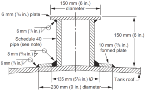
Scaffold Support
undefined
-
-
Inspect scaffold support for corrosion.
-
Is the scaffold support an API standard type attachment?
-
Is there a reinforcing plate present?
-
Pipe diameter (in.)
-
Thickness of pipe
-
Diameter of reinforcing plate (in.)
Insulation
-
Inspect for damage, tears, deteriorated sealant, bulging, wet insulation, etc.
-
Does the insulation limit or prevent inspection of the roof to shell joint?
Standard Venting (rim vent hoods)
-
Verify vents allow free air flow and screens are free from debris.
-
Check and detail vents that have missing screens and/or vent hoods.
-
Verify vent hoods are secured with a pin and in the down position. Check for missing bolting hardware.
Emergency Venting (Mechanical, PRV, PSV, etc.)
-
Check for setting of mechanical vents from the nametag and notate on the fixed roof nozzle table.
-
Check and detail vents that have missing screens and/or vent hoods.
-
Take photos of each vent and tag if present. (even if tag isn’t legible)
Geo-Dome
-
Geo-Dome: Check for evidence of leaking panels (areas of water on the internal floating roof) and damaged panels (tears, holes, etc.)
-
Geo-Dome: Check for pinholes and tears in the roof panels and any visible missing components.
-
Geo-Dome: Check for damaged or deteriorated skylights.
FIXED ROOF RECOMMENDATIONS
-
PHOTO
-
DESCRIPTION
1.4.2 Internal Floating Roof (IFR)
-
Steel: Overall levelness and condition of the floating roof.
Floating Roof Drain(s)
-
Floating Roof Drain Type and Qty.
Primary Seal
-
Inspect seal fabric for deterioration, hole, tears, and cracks.
Secondary Seal
-
Inspect seal fabric for deterioration, hole, tears, and cracks.
Appurtenance Seal(s)
-
Check condition of seal around columns, guide pole(s) and gauge pole(s).
Roof Supports (Floating Roof Legs and Cable Suspension)
-
Inspect legs and sleeves for signs of thinning and corrosion.
Bonding/Grounding
-
Bonding/Grounding: Verify if floating roof is equipped with a minimum of four (4) bonding shunts or a minimum of two (2) flexible multi-strand cables from the fixed roof to the internal roof.
-
Number of Shunts:
-
Number of Cables:
Anti-Rotation
-
Steel: Type of Anti-rotation. Verify condition and if misalignment is present.
Rolling Ladder & Runway
-
Inspect rolling ladder for corrosion.
FLOATING ROOF RECOMMENDATIONS
-
PHOTO
-
DESCRIPTION
1.4.3 External Floating Roof
-
Inspect for pitting, holes, weld corrosion and evidence of product on deck
-
Overall condition of coating system (notate coating failure such as cracks, blistering, chalking, discoloration, rust blooms, adhesion failure, etc.).
-
Verify deck lap seams have been stitch welded within 12 inches of each penetration.
-
Collect and review deck plate UT for significantly low reading(s).
-
Document and identify all recordable indications and defects on the floating roof layout.
-
Check condition of foam dam.
Pontoons
-
Check all pontoons for signs of water, product, residue, and vapors (numbering should begin counterclockwise from the gauge pole).
Nozzle and Appurtenances
-
Inspect condition covers, seals, and gaskets for all floating roof penetrations (e.g., sample hatch, vacuum breakers, manways, etc.).
-
Inspect nozzles for signs of defects, corrosion, and coating failure.
Floating Roof Leg
-
Inspect legs and sleeves for signs of thinning and corrosion.
-
Inspect the High/Low leg pins and holes for corrosion and tears.
-
Inspect legs for distortion and surrounding deck plate for tears or cracking. Verify reinforcing plates are present around legs.
Grounding
-
Has the floating roof been equipped with a grounding system?
Primary Seal
-
Inspect seal fabric for deterioration, hole, tears, and cracks.
Secondary Seal
-
Inspect seal fabric for deterioration, hole, tears, and cracks.
Rolling Ladder & Runway
-
Inspect rolling ladder for corrosion.
-
Inspect for wear and corrosion where rolling ladder attaches to gauging platform.
FLOATING ROOF RECOMMENDATION
-
PHOTO
-
DESCRIPTION
1.4.4 Tank Gauging
External Gauge
-
Inspect automatic gauge housing for damage.
-
Detail Make, Model No., Serial No. and Mfr. Date. of tank gauge
Internal Gauge
undefined
-
-
Gauge Pole Details: Size: Slotted? ☐ Yes, Slot Size:
-
Check for gauge well corrosion and/or distortion.
-
Check if the gauge pole supports are welded to the shell or repad and not the bottom. Check support welds for corrosion or defects.
-
Check condition of gauge well seal system (i.e., ‘sock’). Typically present on tanks with floating roofs.
TANK GAUGING RECOMMENDATION
-
PHOTO
-
DESCRIPTION
Inspector
-
API Inspector:
-
API Cert #:
-
REFERENCE PHOTOGRAPHS
- OVERVIEW
-
OVERVIEW
-
DESCRIPTION
FOUNDATION
-
FOUNDATION
-
DESCRIPTION
EDGE PROJECTION
-
EDGE PROJECTION
-
DESCRIPTION
SHELL
-
SHELL
-
DESCRIPTION
SHELL NOZZLES AND APPURTENANCES:
-
SHELL NOZZLES AND APPURTENANCES:
-
DESCRIPTION
FIXED ROOF:
-
FIXED ROOF:
-
DESCRIPTION
FIXED ROOF NOZZLES
-
FIXED ROOF NOZZLE
-
DESCRIPTION
FLOATING ROOF:
-
FLOATING ROOF:
-
undefined