


Information
-
Pole Number
-
Bank KVAR
-
Location
-
Client / Site Name (Optional)
-
Conducted on
Positions PRIOR to Testing
-
CUTOUTS
-
SWITCHES
-
CONTROL
OPEN TEST
-
Put the control on "Manual"
-
With the control, "Open" ("Trip") the bank
-
"Open" the load-break cutouts
-
Wait at least 5 Minutes for the Capacitors to safely discharge
Check that the oil / vacuum switches open correctly
-
IF a switch does not open, check the secondary connections to insure control voltage is getting to the switch.
Some of our new capacitor controls only send a pulsed control voltage signal (not a constant voltage) -
IF Secondary Control Voltage is absent, repairing secondary wires or the control may resolve the issue.
Switch Successfully Opened
-
A phase
-
B phase
-
C phase
-
Notes
-
Replace any questionable switches
-
CLOSE TEST
-
Visually inspect the capacitor bank for any signs of problems (e.g. bulging, leaking, broken bushings, ...)
-
IF there are any signs of damage, DO NOT "Close" the bank until the damages are repaired
-
Please note any damage or repairs made.
-
Close all the cutouts
-
"Close" the bank using the control"
-
Verify all the oil / vacuum switches closed correctly
Check that the oil / vacuum switches open correctly
Switches Successfully Closed
-
A phase
-
B phase
-
C phase
-
Notes
-
IF a switch does not close, check the secondary connections to insure control voltage is getting to the switch.
Some of our new capacitor controls only send a pulsed control voltage signal (not a constant voltage) -
IF Secondary Control Voltage is absent, repairing secondary wires or the control may resolve the issue.
Amp probe the leads from each cutout / oil or vacuum switch
Current Readings [Amps]
-
A phase
-
B phase
-
C phase
-
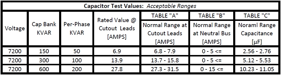
The amp readings above the cutout, below the CL fuse, and in / out of the switch should all be the same.
-
IF all three currents are within the normal range (see Table "A"), then the fuses, oil/vacuum switches, and capacitors are "OK"
-
IF ANY phase reads "Zero" amps, then a fuse, switch, or capacitor could be bad.
-
Check the fuse by fuzzing or taking a primary voltage reading on the LOAD side of the fuse
-
Check the "primary section" of the switch by fuzzing or taking the primary voltage reading on the LOAD side of the switch
Amp probe the neutral bus conductor past the last capacitor in the lead connecting to the system neutral
-
Neutral Reading [Amps]
-
IF this value is in the normal range (see Table "B"), then connections, equipment, and harmonics are probably not a problem
-
Are the readings within normal ranges?
-
Final Steps
-
Test Summary
Positions AFTER Testing
-
CUTOUTS
-
SWITCHES
-
CONTROL
-
Counter Reading on control (if available)
-
Prepared by
-
Signature
-
Date | Time

