")


Title Page
-
Conducted on
-
Prepared by
-
Location
-
Version Control - 1.5
PURPOSE
-
The purpose of this document is to assist field teams, designers, OHS and other Gigacomm employees and partners to assess a buildings viability for a Gigacomm service. This Document designed to assist in the understanding of the building topography and layout for design, installation and safety requirements for Gigacomm services and future upgrades.
Image requirements
-
Photo Type: Standard - Used for site access, cable routes, overall photos and general site photos - Resolution: 1074 x 768 - File Type: JPEG – Ratio: 4:3 – Size: <500kb
-
Photo Type: High resolution photos - Used for line-of-sight photos, N/S/E/W photos - Resolution: 5168x 3872 - File Type: JPEG – Ratio: 4:3 - Size: 5Mb
SITE DESIGN BRIEF
ARTEFACTS AND COMMENTS
-
Building external photos
-
Building Access - photo from street to front entrance
-
Photos of common areas (Walkways, corridors, foyer)
-
Letter Box Photos
-
Building onsite Floor Plans or Fire Evacuation Diagram
-
Photo of Fire Stairs
TECHNOLOGY MIX
-
mmWave dish and Node broadcast antenna?
-
Node CPE?
-
Dark Fibre?
LEAD-IN CONDUIT TO PROPERTY
-
Please provide a photo of the existing Building Entry Point (BEP) - lead-in conduit within the building
-
Please provide a photos of the existing path from Building Entry Point (BEP) to MDF
-
Please provide photo of available capacity of lead-in conduit
-
What floor is the BEP for Telstra and/or NBN Lead in
MDF Details
-
Identify Building Eg. 1 of 3 or Block A
-
MDF access - photo of access to control/equipment room
-
Which floor is the MDF on? (please comment about location)
-
Which floors/apartments are served by MDF?
-
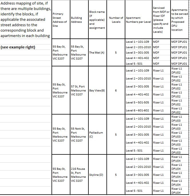
Provide a mark up for Address mapping of the site, if there are multiple buildings, identify the blocks, if applicable the associated street address to the corresponding block and apartments in each building, including levels and apartment numbers. Please see example.
-
-
Distance from MDF to vertical risers, please include red line mark ups with comments (what is the length horizontally along cable tray routes?)
-
Provide photos of Horizontal cable routes and penetrations - identify horizontal penetrations (if applicable) and cable route, 1x photo per 5m (or corner bend if applicable, multiple photos maybe required)
-
Provide photos of proposed equipment locations including measurements
-
Provide markup photo with measurement of proposed space
-
Provide Photos of all MDF Jumpering Record Book and all written pages
-
Provide 360 degree photos of MDF Room
-
Provide photos of existing existing Krone Frame
-
Provide photos of existing cable tray and highlight any new cable tray required including length
-
Provide general photos of any existing Carriers Equipment in and around the MDF Room
Riser/IDF Details
-
Identify Building Eg. 1 of 3 or Block A
-
What floors are the IDFs on?
-
Which IDFs service which floors/apartments?
-
Provide Photos of all Risers. Photo of entire riser including left and right wall (wide angle)
-
Provide close up photos of existing and proposed new penetrations.
-
Provide photos of Horizontal cable routes and penetrations - identify horizontal penetrations (if applicable) and cable route, 1x photo per 5m (or corner bend if applicable, multiple photos maybe required)
-
Provide photos of proposed equipment locations including measurements
-
Mark up (Photo) Cables feeding in/out of the proposed Gigacomm device location such as riser run Horizontal, Vertical and or Other
-
MDF to Riser distance?
-
Riser to furthest apartment distance?
-
Height of each floor (m)?
-
Riser locations are the same across floors of the building, if not, please raise it as “cable length risk”?
-
Provide Photos of all IDF Jumpering Record Book and all written pages
IN BUILD EQUIPMENT
-
Roof top wall box (RTWB)?
-
FOBOT?
-
DPU?
-
Cabinet type? (9RU, 6RU, 5RU Vertical, 4RU)
-
Will the equipment cabinet be in a location other than MDF Room or where Telstra Lead-in comes in?
-
If cabinet is proposed in another location other the MDF, provide path and distance for a fibre cable tie from HD FOBOT to 9 RU. ( Please note: this is required even if an antenna mount design is proposed).
ROOF TOP INFORMATION
-
Identify Building Eg. 1 of 3 or Block A
-
Rooftop access - photo of exit to rooftop
-
Provide measurement of roof access hatch or door.
-
Will there be sufficient space to transport antenna equipment and mast through?
-
Are you proposing to utilise an existing Penetration from rooftop to Riser?
-
Provide photo markup of new proposed penetration location
-
Provide photos of Horizontal cable routes and penetrations - identify horizontal penetrations (if applicable) and cable route, 1x photo per 5m (or corner bend if applicable, multiple photos maybe required)
-
Check for suitable location to install Gigacomm equipment (antenna to be installed at highest practical location allowing for a 360* panorama view, Rooftop wallbox to be installed at a height for easy access/maintenance)
-
Roof top Photos showing LOS for 360 degrees
-
If B end building information has been supplied, please provide - min 2 photos to proposed B end building 1. general direction 2. zoom into building (high-res photo)
-
Check for existing rooftop earthing and provide photo. (earthing bar, existing steel structure, existing lighting arrestor)
-
If NO existing earthing - propose suitable path to nearest earth point or switch room earth bar. (Include photo markup)
-
Mark-up distance from existing arrestor to propose antenna frame/dish
-
Provide photos of existing anchor points and current proof of valid certification.
Mount Adequacy
-
Host Building Conditions 1. The masonry or the concrete within 1m2 of the mount fixing points are free of loose
materials, cracks and other structural defects
2. The timber trusses on which the mount and braces are to be fixed are free of
rotten/damaged points and other structural defects
3. Minimum thickness of host concrete roof/wall is to be 150mm
4. Minimum thickness of host cavity brick wall is to be 270mm
5. Minimum thickness of host solid brick wall it to be 230mm
6. An experienced site supervisor is to confirm the building conditions as above specified
or seek further suggestions from ServiceStream structural engineers if anything
uncertain. -
What is the roof structure Type?
-
Provide photos of underneath roof structure if possible?
-
Timber trusses on which the mount and braces are to be fixed are free of rotten/damaged points and other structural defects
-
If timber/metal truss (purlins), what is the distance between the trusses?
-
Brick or concrete - provide WALL thickness
-
Brick or concrete- provide ROOF thickness
-
The masonry or the concrete within 1m2 of the mount fixing points are free of loose materials, cracks and other structural defects
-
Mount Adequacy photos showing roof material structure and structural details
-
Markup proposed location of antenna on photos
-
Show Building height using nearmap/google earth
PROPOSED EQUIPMENT DETAILS
-
Identify Building Eg. 1 of 3 or Block A
-
Proposed Rooftop ANTENNA Location
-
Mark up photos to show equipment connection - Antenna to RTWB to 9RU to each FOBOT & DPU & GPO
-
Distance between RTWB & Riser (m). Provide marked up photos to support
-
What is Distance b/w RTWB & 9RU Cabinet (m)? Maximum distance for 9RU cabinet and antenna is 100m for PoE limitation (Ideally as close to antenna as possible. Eg. Lift Motor Room/Plant Room)
-
Proposed DPU LOCATION (s)?
-
Provide a breakdown of the furthest apartment measurements for each proposed DPU as follows: 1. DPU to MDF/IDF 2. MDF/IDF to Vertical Riser 3. Riser to Furthest Apartment (Including 10m for internal apartment measurement)
Proposed Electrical Power Connections
-
1. If the proposed equipment is in the main electrical switch room then propose the new power feed from the Main House Distribution Board. (Not Main Switch board or Tenant Board) otherwise propose power connection from an existing GPO and highlight the services connected to it. 2. If the electrical room is in a separate location other than proposed equipment location, provide photos of the electrical room and the cable path to the proposed equipment location (As a back-up option always scope Electrical room during survey).
-
Provide photos GPO or House Distribution Board which can be used to power up Equipment Cabinet and each DPU at each location? Provide photos of path of power source to be used.
EXISTING SERVICES – OTHER CARRIER
-
Can you identify any other ISPs, carriers or relevant parties in equipment rooms, on RTs and in general work area in MDF room (NBN, TPG, Telstra)
SITE SPECIFIC
-
"If an Antenna is to be installed how would the steelwork/3.5m pole get to roof top?
-
Are mechanical aids required, for antenna installation? i.e. EWP, Large Ladders etc? If yes, please detail
-
“Fire/Smoke alarms isolation needed?”
-
“ Power Outage is required or not”
-
“ Third Party Carrier ie TPG or NBN need to be notified for Temporary Outage or Installation activities”
NEAR MAP OR GOOGLE EARTH MARK-UP
-
Mark up location of proposed cable route and MDF/IDF/RISERS/Proposed antenna location using google earth/nearmap (required for a multi building site)
-
Provide a Strata Plan cable path markup for all horizontal and Lead-in cable paths for each floor where new cables are proposed.
Build-ability Risks
-
Based on the inspection highlight any risks that will effect the build ability of this site? Eg. Lead-in Duct and riser cupboards and other cable paths
-
Additional comments about cable route (include potential obstructions, building material for penetrations)
DEPENDENCIES, RISKS AND HAZARDS
-
Any Site specific risks and hazards?
-
Working at Heights?
-
Confines Spaces?
-
Asbestos and or Asbestos Register on site?
-
Trips Hazards?
-
Any other risks or Hazards?
GENERAL BUILDING INFORMATION
-
Confirm site access contact details (bldg. manager/owner Contact detail if applicable):
-
Is there any known special access or security requirements for the site and any surrounding buildings or floors? (if yes, please ask for details) E.g. Supplying evidence of qualifications and licenses.
-
Is there a site induction required?
-
Can site be accessed 24/7? (If yes, request for out of hours contact details):
-
Does site consist of multiple building?
-
Building Height (m)?
-
Does site have alternate address or 2nd building entry point from side or cross St?
-
Parking and material unloading details, i.e. loading dock, street only etc:
Embedded Network - (Free- to-Air Coax utilisation)
-
This section is to be filled out if it is determined that an embedded carrier network services the site and we can consider utilising the free-to-air coax system within the building. (Surveyor is required to contact the allocated Service Stream Designer whilst on site)
-
Does the site currently utilise an embedded network to supply their internet services?
-
Define the Embedded Network provider
-
Is there a, base building owned, structured copper cabling network throughout the building and to all apartments that can be utilised for a GigaComm standard installation?
-
Proceed with SDV as per standard installation requirement
-
Proceed with FTA Coax survey
-
Proceed with SDV as per standard installation requirement
-
Identify satellite and Free-to-air antenna’s (FTA) on rooftop. Provide photos.
-
Find ‘first’ splitter and/or amplifier and identify whether the coax is one of the following:
-
a. Shared (Sat and FTA)
-
b. Single use Satellite
-
c. Single use FTA
-
Number of coax cables exiting each riser on each apartment floor
-
The type of coaxial cable (RG59, RG6, RG11) – RG59 is bad, RG6 is good, RG11 is best
-
Provide description of model names and technologies used for splitters, amplifiers, diplexers.
-
Provide High-res photos of splitters, amplifiers, diplexers etc so as to identify operating frequencies (ie. 5 – 694MHz, 5 – 2400MHz etc)
-
Provide a existing FTA network diagram on elevation view showing rooftop cable entry to splitters, amplifiers, diplexers etc including signal direction (in/out)