


Title Page
-
Trial #
- T1
- T2
- T3
- T4
- Pre-Grain
- Post-Grain
-
Have all previously identified issues been resolved?
-
Have all previously identified issues been resolved?
-
Have all previously identified issues been resolved?
-
Have all previously identified issues been resolved?
-
Have all previously identified issues been resolved?
-
Customer
-
Tycos Job #
-
Division Tool #
-
Part Number
-
Part Description
-
Conducted on
-
Completed by
-
Trial Location Name
-
Trial Location
-
Type of Facility
-
Sample Type
- 1st Shots
- Final Verification
- Issue Verification
- Part Run
- Run @ Rate
- DOE
- Support
-
Tool Builder Name
-
Tool Builder Job #
-
Tycos Program Manager Present?
-
Tycos Program Manager Name
-
Tycos Program Manager Representative Name
-
Tycos Program Manager Name
-
Tool Builder Program Manager Present?
-
Tool Builder Program Manager Name
-
Tool Builder Program Manager Representative Name
-
Tool Builder Program Manager Name
-
Plant Tool Engineer Present?
-
Plant Tool Engineer Name
-
Plant Tool Engineer Representative Name
-
Plant Tool Engineer Name
-
Plant Program Manager / Project Engineer Present?
-
Plant Program Manager / Project Engineer Name
-
Plant Program Manager / Project Engineer Representative Name
-
Plant Program Manager / Project Engineer Name
-
Plant Process Engineer Present?
-
Plant Process Engineer Name
-
Plant Process Engineer Representative Name
-
Plant Process Engineer Name
-
Plant Quality Engineer Present?
-
Plant Quality Engineer Name
-
Mouldflow Analyst Present?
-
Mouldflow Analyst Name
-
Material Supplier Present?
-
Material Supplier Name
-
Additional People Present at the Trial
-
Observations About the Trial Facilities and Attendees
Report Instructions
General Report Instructions
-
1. Answer all questions provided below
-
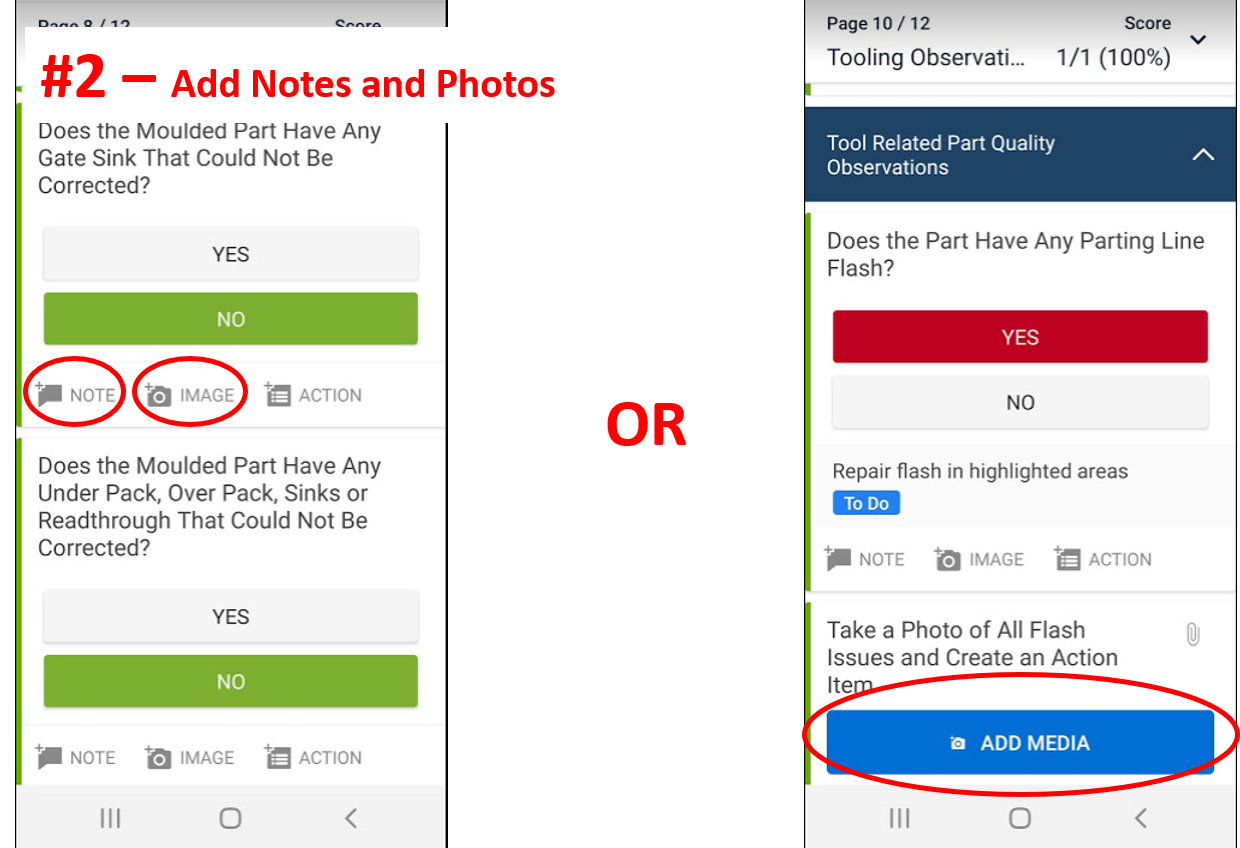
2. Add photos and notes by clicking on the appropriate icon.
-
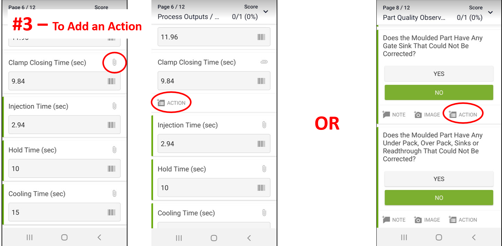
3a. To add a Corrective Action, click on the paperclip icon then "Add Action", or the "Action" icon,
-
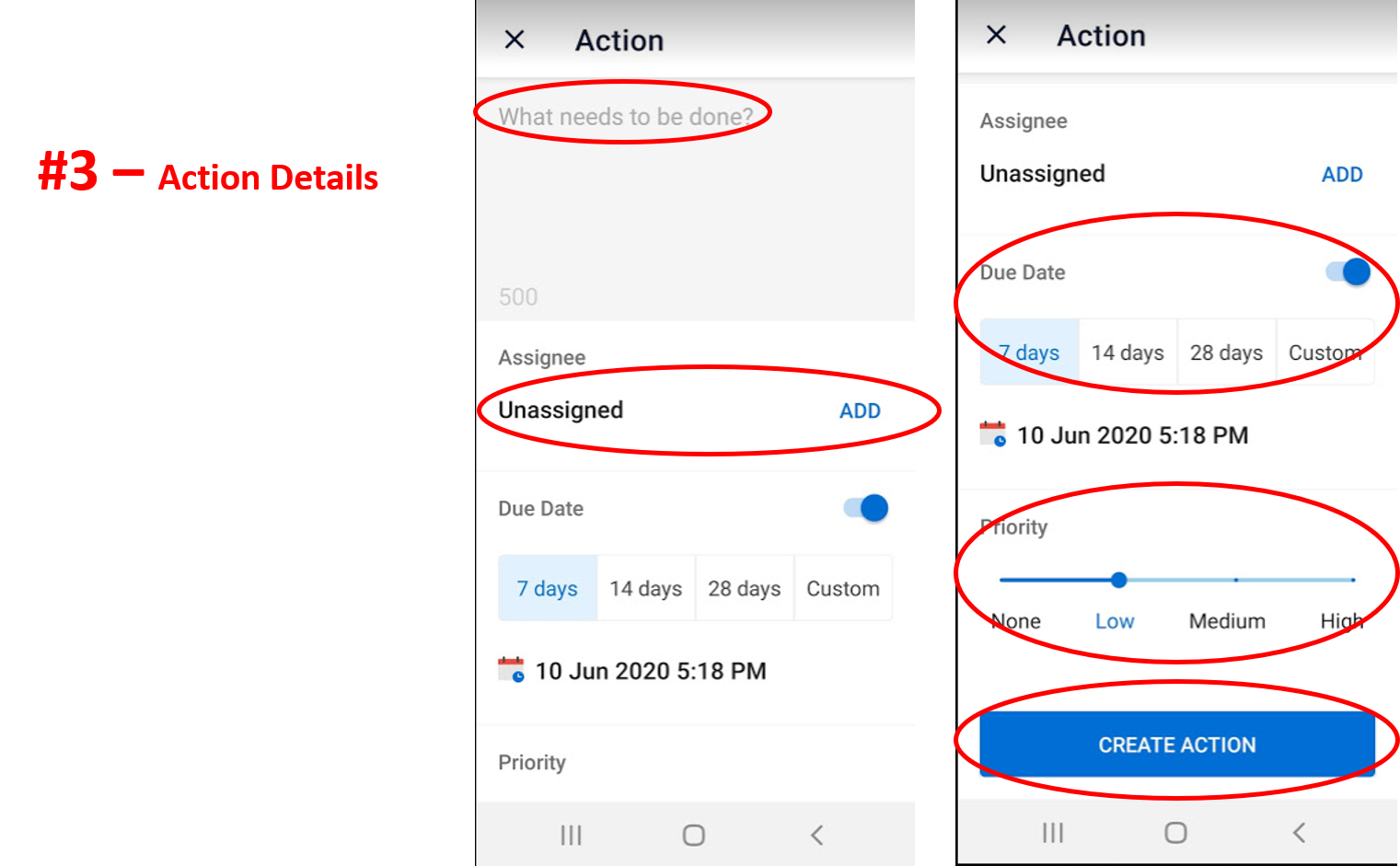
3b. For each action, provide a description of what needs to be done, assign to a member, set due date and priority, and click "Create Action".
-
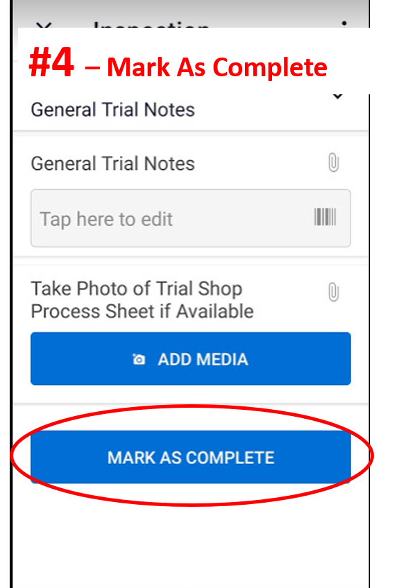
4. Complete audit by clicking on "Mark As Complete", only when ALL questions have been answered.
-
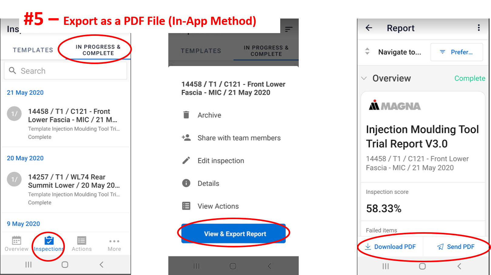
5a. Share your report by exporting as a PDF file. The report can be shared from within the app.
-
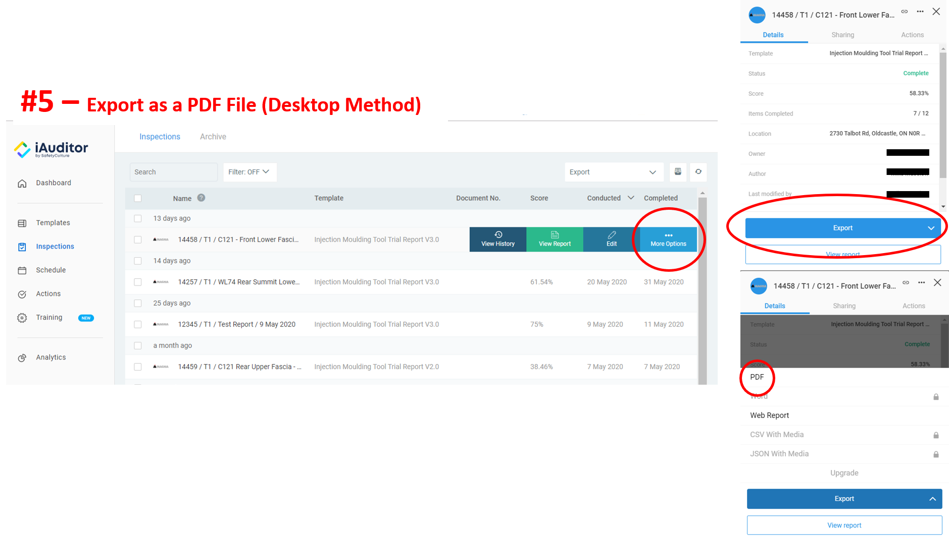
5b. The report can also be shared from the desktop website as well.
Physical Units and Reference
Physical Units
-
Select All Physical Units To Be Used For This Report Unless Otherwise Indicated
-
Temperature Units
-
Position Units
-
Pressure Units
-
Weights
-
Clamp Force Units
Reference Documents
-
Take Photo of Valve Gate Layout if Available
Resin and Machine Details
Resin Details
-
Resin Manufacturer
-
Resin Grade - (3325, 342EZ, ADX2335, 1168X, etc)
-
Resin Type - (PP, PC/ABS, Acetal, etc)
-
If Multiple Components are Blended, What is the Blend Ratio?
-
For Blended Materials, What Equipment is Used For Blending?
- Gravimetric Weigh Blender
- Additive Auger
- Press Side Mixing Drum
- Mix By Hand/Shovel
- Pre-Blended By Supplier
- No Blending Required
-
Multiple Colours?
-
Colour Code (If Required)
-
For Long Fibre Filled Materials, What is the Average Pellet Length? (mm)
-
Resin Dry Time - (hrs)
-
Resin Dry Temperature
-
If Material is Dried (Hygroscopic), What is the Moisture Content?
-
Target Shrink Rate - (mm/1000)
-
Take Photo of All Material Labels
-
Take Photo of the Resin for Future Reference
Machine Details
-
Name of Press
-
Intensification Ration - (# : 1)
-
Screw Diameter - (mm)
-
Barrel Size - (grams)
-
Tonnage of Press (Metric Tons)
-
Clamp Style
- Hydraulic Ram
- Hydraulic Toggle
- Electric Toggle
- Two Platen Hydra-mechanical
- Electric Servo
- Other
-
Observations About The Resin and Machine Details
Mould Flow Report - Process Starting Points
-
For the T1 trial , the mould flow report should be used for the process inputs. For all subsequent trials, use the process inputs from the previous trial
-
Trial #
- T1
- T2
- T3
- T4
- Pre-Grain
- Post-Grain
-
Is There Another Process With Targets For This Trial?
-
Reference Process Intensification Ratio - (#:1)
-
Reference Process Screw Diameter - (mm)
-
Target Melt Temperature
-
Target Cavity Steel Temperature
-
Target Core Steel Temperature
-
Hot Runner Temperature
-
Fill Time (Seconds)
-
Volumetric Fill Speed (cm^3/sec)
-
Volume % Filled Before Transfer
-
Pack/Hold Time
-
Pack/Hold Pressure (Plastic Pressure)
-
Gate Freeze Time
-
Cooling Time
-
Recovery Time
-
Clamp Force Used
-
Maximum Injection Pressure
-
Injection Pressure at Transfer
-
Total Part/Shot Weight - Transfer Only / No Holding Pressure
-
Total Part/Shot Weight - Fully Packed Out
-
Include Picture of Reference Process Sheet
-
Was a Mould Flow Completed For This Tool?
-
Mould Flow Theoretical Starting Points
-
Mould Flow Source
- Magna - Troy ESE
- Magna - Internal Division
- Bozilla Corp
- CAE Services
- FEA Mold
- Material Supplier
- Tool Source
- Other
-
Name of Mould Flow Source
-
Name of Material Supplier
-
Name of Tool Source
-
Name of Mould flow Analyst
-
Mould Flow Report File Name
-
Target Melt Temperature
-
Target Cavity Steel Temperature
-
Target Core Steel Temperature
-
Target Fill Time (Seconds)
-
Target Fill Speed - (cm^3/sec)(Still need to match fill time)
-
V/P Control Metric - ##% Volume Filled Before Transfer
-
Target Pack/Hold Time
-
Target Pack/Hold Pressure - % of V/P Transfer Pressure
-
Target Pack/Hold Pressure (Plastic Pressure)
-
Target Gate Freeze Time
-
Target Cooling Time
-
Target IPC (Injection, Pack, and Cooling) Time
-
Predicted Clamp Force
-
Predicted Maximum Injection Pressure
-
Predicted Injection Pressure at Transfer
-
Target Part/Shot Weight
-
Total Shot Volume
-
Valve Gate Trigger Reference Map
-
Number of Valve Gate Triggers
-
Valve Gate Trigger 1 (T1) Time (sec)
-
Valve Gate Trigger 1 (T1) Position (mm)
-
Valve Gate Trigger 2 (T2) Time (sec)
-
Valve Gate Trigger 2 (T2) Position (mm)
-
Valve Gate Trigger 3 (T3) Time (sec)
-
Valve Gate Trigger 3 (T3) Position (mm)
-
Valve Gate Trigger 4 (T4) Time (sec)
-
Valve Gate Trigger 4 (T4) Position (mm)
-
Valve Gate Trigger 5 (T5) Time (sec)
-
Valve Gate Trigger 5 (T5) Position (mm)
-
Valve Gate Trigger 6 (T6) Time (sec)
-
Valve Gate Trigger 6 (T6) Position (mm)
-
Valve Gate Trigger 7 (T7) Time (sec)
-
Valve Gate Trigger 7 (T7) Position (mm)
-
Valve Gate Trigger 8 (T8) Time (sec)
-
Valve Gate Trigger 8 (T8) Position (mm)
-
Valve Gate Trigger 9 (T9) Time (sec)
-
Valve Gate Trigger 9 (T9) Position (mm)
-
Valve Gate Trigger 10 (T10) Time (sec)
-
Valve Gate Trigger 10 (T10) Position (mm)
-
Is There Another Process With Targets For This Trial?
-
Reference Process Intensification Ratio - (#:1)
-
Reference Process Screw Diameter - (mm)
-
Target Melt Temperature
-
Target Cavity Steel Temperature
-
Target Core Steel Temperature
-
Hot Runner Temperature
-
Fill Time (Seconds)
-
Volumetric Fill Speed (cm^3/sec)
-
Volume % Filled Before Transfer
-
Pack/Hold Time
-
Pack/Hold Pressure (Plastic Pressure)
-
Gate Freeze Time
-
Cooling Time
-
Recovery Time
-
Clamp Force Used
-
Maximum Injection Pressure
-
Injection Pressure at Transfer
-
Total Part/Shot Weight - Transfer Only / No Holding Pressure
-
Total Part/Shot Weight - Fully Packed Out
-
Include Picture of Reference Process Sheet
Process Details
Process Inputs
-
Projected Tonnage To Be Used
-
Actual Tonnage Used For Process
Temperatures
Barrel Temperatures
-
Rear Zone
-
Middle Zone 1
-
Middle Zone 2
-
Middle Zone 3
-
Front Zone
-
Barrel Head / Adaptor
-
Nozzle
-
Take Photo of Barrel Heat Profile
Hot Runner Temperatures
-
Number of Hot Runner Zones
-
Are All Zones Set to the Same Temperature?
-
Define which zones are different, the temperature, and the reason why.
-
Temperature of All Zones
-
Is the Hot Runner Manifold Working Properly as it was Intended?
-
Do All Hot Runner Zones Come Up To Temperature and Hold Temperature Within 5 Degrees?
-
Which Zones Do Not Hold Temperature?
-
Take a Photo of All Hot Runner Manifold Issues and Create an Action Item
-
Do All Hot Runner Zones Come Up To Temperature and Hold Temperature Within 5 Degrees?
-
Which Zones Do Not Hold Temperature?
-
Take Photo of all of the Hot Runner Screens
Tool Temperatures
-
Target Number of Cavity Water Zones
-
Number of Cavity Water Zones Used
-
Cavity Zone 1 Temperature
-
Cavity Zone 2 Temperature
-
Cavity Zone 3 Temperature
-
Cavity Zone 4 Temperature
-
Cavity Zone 5 Temperature
-
Target Number of Core Water Zones
-
Number of Core Water Zones Used
-
Core Zone 1 Temperature
-
Core Zone 2 Temperature
-
Core Zone 3 Temperature
-
Core Zone 4 Temperature
-
Core Zone 5 Temperature
-
Number of Auxiliary Water Zones
-
Auxiliary Zone 1 Temperature
-
Auxiliary Zone 2 Temperature
-
Auxiliary Zone 3 Temperature
Injection Profile
-
Take Photo of Injection Profile
-
Number of Injection Profile Steps
-
Define the Injection Speed Profile
-
Explain Why More Than One Step is Needed
-
Injection Speed Used
-
Max Injection Pressure Setpoint
-
Transfer Position
-
If Injection Speed is in %, What is the Maximum Physical Speed?
-
If Injection Pressure is in %, What is the Maximum Physical Pressure?
Pack / Hold Profile
-
Take Photo of Pack/Hold Profile
-
Number of Hold Pressure Steps
-
First Hold Time (sec)
-
First Hold Pressure
-
Second Hold Time (sec)
-
Second Hold Pressure
-
Third Hold Time (sec)
-
Third Hold Pressure
-
Fourth Hold Time (sec)
-
Fourth Hold Pressure
-
Fifth Hold Time (sec)
-
Fifth Hold Pressure
-
Sixth Hold Time (sec)
-
Sixth Hold Pressure
-
Seventh Hold Time (sec)
-
Seventh Hold Pressure
-
Eighth Hold Time (sec)
-
Eighth Hold Pressure
-
Ninth Hold Time (sec)
-
Ninth Hold Pressure
-
Tenth Hold Time (sec)
-
Tenth Hold Pressure
-
If Pack/Hold Pressure is in %, What is the Maximum Physical Pressure?
Recovery Profile
-
Take Photo of Recovery Profile
-
Set Back Pressure
-
Set Screw Speed
-
Calculated Screw Surface Speed (mm/sec) - (Screw Diameter x 3.14159 x RPM / 60)
-
If Back Pressure is in %, What is the Maximum Physical Pressure?
-
If Screw Speed is in %, What is the Maximum Physical Screw Speed?
Valve Gates
-
Valve Gate Type
-
Number of Valve Gates
-
Valve Gate Trigger for Injection
-
Take Photo of Valve Gate Injection Settings
-
Take Photo of Valve Gate Pack/Hold Settings
-
Does the Correct Valve Gate Control Number Operate the Correct Valve Gate?
-
Which Valve Gates Do Not Match the Correct Control
Valve Gate Speed Monitoring
-
Are You Able to Monitor the Valve Pin Opening Times With a Synventive Valve Monitoring Interface Module?
-
Number of Valve Gates Monitored
-
Valve Pin 1 Opening Time (sec)
-
Valve Pin 2 Opening Time (sec)
-
Valve Pin 3 Opening Time (sec)
-
Valve Pin 4 Opening Time (sec)
-
Valve Pin 5 Opening Time (sec)
-
Valve Pin 6 Opening Time (sec)
-
Valve Pin 7 Opening Time (sec)
-
Valve Pin 8 Opening Time (sec)
-
Valve Pin 9 Opening Time (sec)
-
Valve Pin 10 Opening Time (sec)
-
Valve Pin 11 Opening Time (sec)
-
Valve Pin 12 Opening Time (sec)
-
Valve Pin 13 Opening Time (sec)
-
Valve Pin 14 Opening Time (sec)
-
Valve Pin 15 Opening Time (sec)
-
Valve Pin 16 Opening Time (sec)
-
Valve Pin 17 Opening Time (sec)
-
Valve Pin 18 Opening Time (sec)
-
Valve Pin 19 Opening Time (sec)
-
Valve Pin 20 Opening Time (sec)
-
Valve Pin 21 Opening Time (sec)
-
Valve Pin 22 Opening Time (sec)
-
Valve Pin 23 Opening Time (sec)
-
Valve Pin 24 Opening Time (sec)
-
Attach Pictures of All Valve Pin Monitoring Times
-
Observations About Process Inputs
Process Outputs / Timers / Weights
Process Outputs
-
Melt Temperature
-
Maximum Injection Pressure
-
Injection Pressure at V/P Transfer
-
Full Shot Stroke
-
V/P Transfer Position
-
Cushion Position
-
Take a Photo of the Process Output Screen
Process Timers
-
Target Production Cycle Time (sec)
-
Actual Cycle Time (sec)
-
If Cycle Time Is Not Within 2 Seconds of the Target, Briefly Explain Why Not.
-
Clamp Opening Time (sec)
-
Clamp Closing Time (sec)
-
Injection Time (sec)
-
Hold Time (sec)
-
Cooling Time (sec)
-
Recovery Time (sec)
-
Calculated Residence Time (sec) - (Barrel Full Shot Stroke Available / Process Full Shot Stroke x Cycle Time)
-
Take a Photo of the Cycle Time Breakdown Screen
Part Weights and Measurements
-
Number of Cavities
-
Zero Hold Weight
-
Full Weight
-
Scribe Line Measurement - What is the Scribe Scale?
-
Scribe Line Measurement
-
Runner Weights
-
Zero Hold Weight - Cavity 1 (Left)
-
Zero Hold Weight - Cavity 2 (Right)
-
Full Weight - Cavity 1 (Left)
-
Scribe Line Measurement - Cavity 1 (Left) - What is the Scribe Scale?
-
Scribe Line Measurement
-
Full Weight - Cavity 2 (Right)
-
Scribe Line Measurement - Cavity 2 (Right) - What is the Scribe Scale?
-
Scribe Line Measurement
-
Runner Weights
-
Zero Hold Weight - Cavity 1
-
Zero Hold Weight - Cavity 2
-
Zero Hold Weight - Cavity 3
-
Full Weight - Cavity 1
-
Scribe Line Measurement - Cavity 1 - What is the Scribe Scale?
-
Scribe Line Measurement
-
Full Weight - Cavity 2
-
Scribe Line Measurement - Cavity 2 - What is the Scribe Scale?
-
Scribe Line Measurement
-
Full Weight - Cavity 3
-
Scribe Line Measurement - Cavity 3 - What is the Scribe Scale?
-
Scribe Line Measurement
-
Runner Weights
-
Zero Hold Weight - Cavity 1
-
Zero Hold Weight - Cavity 2
-
Zero Hold Weight - Cavity 3
-
Zero Hold Weight - Cavity 4
-
Full Weight - Cavity 1
-
Scribe Line Measurement - Cavity 1 - What is the Scribe Scale?
-
Scribe Line Measurement
-
Full Weight - Cavity 2
-
Scribe Line Measurement - Cavity 2 - What is the Scribe Scale?
-
Scribe Line Measurement
-
Full Weight - Cavity 3
-
Scribe Line Measurement - Cavity 3 - What is the Scribe Scale?
-
Scribe Line Measurement
-
Full Weight - Cavity 4
-
Scribe Line Measurement - Cavity 4 - What is the Scribe Scale?
-
Scribe Line Measurement
-
Runner Weight
-
Zero Hold Weight - Cavity 1
-
Zero Hold Weight - Cavity 2
-
Zero Hold Weight - Cavity 3
-
Zero Hold Weight - Cavity 4
-
Zero Hold Weight - Cavity 5
-
Full Weight - Cavity 1
-
Scribe Line Measurement - Cavity 1 - What is the Scribe Scale?
-
Scribe Line Measurement
-
Full Weight - Cavity 2
-
Scribe Line Measurement - Cavity 2 - What is the Scribe Scale?
-
Scribe Line Measurement
-
Full Weight - Cavity 3
-
Scribe Line Measurement - Cavity 3 - What is the Scribe Scale?
-
Scribe Line Measurement
-
Full Weight - Cavity 4
-
Scribe Line Measurement - Cavity 4 - What is the Scribe Scale?
-
Scribe Line Measurement
-
Full Weight - Cavity 5
-
Scribe Line Measurement - Cavity 5 - What is the Scribe Scale?
-
Scribe Line Measurement
-
Runner Weight
-
Zero Hold Weight - Cavity 1
-
Zero Hold Weight - Cavity 2
-
Zero Hold Weight - Cavity 3
-
Zero Hold Weight - Cavity 4
-
Zero Hold Weight - Cavity 5
-
Zero Hold Weight - Cavity 6
-
Full Weight - Cavity 1
-
Scribe Line Measurement - Cavity 1 - What is the Scribe Scale?
-
Scribe Line Measurement
-
Full Weight - Cavity 2
-
Scribe Line Measurement - Cavity 2 - What is the Scribe Scale?
-
Scribe Line Measurement
-
Full Weight - Cavity 3
-
Scribe Line Measurement - Cavity 3 - What is the Scribe Scale?
-
Scribe Line Measurement
-
Full Weight - Cavity 4
-
Scribe Line Measurement - Cavity 4 - What is the Scribe Scale?
-
Scribe Line Measurement
-
Full Weight - Cavity 5
-
Scribe Line Measurement - Cavity 5 - What is the Scribe Scale?
-
Scribe Line Measurement
-
Full Weight - Cavity 6
-
Scribe Line Measurement - Cavity 6 - What is the Scribe Scale?
-
Scribe Line Measurement
-
Runner Weight
-
Are the Scribe Line Measurements Within Tolerance?
-
If Mould Flow Theoretical Starting Points Were Used, Did They Give an Accurate Prediction of the Required Process?
-
Observations About Process Outputs and Weights
Short Shot Progression
-
Set the Transfer Position to Each of the Valve Gate Trigger Positions for Each Short Shot
-
How Many Short Shot Stages Were Taken?
-
1st Transfer Position Set to?
-
Fill Time at 1st Set Transfer Position
-
Take Photo of 1st Transfer Short Shot
-
1st Transfer Position Set to?
-
Fill Time at 1st Set Transfer Position
-
Take Photo of 1st Transfer Short Shot
-
2nd Transfer Position Set to?
-
Fill Time at 2nd Set Transfer Position
-
Take Photo of 2nd Transfer Short Shot
-
1st Transfer Position Set to?
-
Fill Time at 1st Set Transfer Position
-
Take Photo of 1st Transfer Short Shot
-
2nd Transfer Position Set to?
-
Fill Time at 2nd Set Transfer Position
-
Take Photo of 2nd Transfer Short Shot
-
3rd Transfer Position Set to?
-
Fill Time at 3rd Set Transfer Position
-
Take Photo of 3rd Transfer Short Shot
-
4th Transfer Position Set to?
-
Fill Time at 4th Set Transfer Position
-
Take Photo of 4th Transfer Short Shot
-
5th Transfer Position Set to?
-
Fill Time at 5th Set Transfer Position
-
Take Photo of 5th Transfer Short Shot
-
6th Transfer Position Set to?
-
Fill Time at 6th Set Transfer Position
-
Take Photo of 6th Transfer Short Shot
-
Is the Part Fill Balanced?
-
Take a Photo of the Imbalanced Area
-
Observations About Short Shot Progression
Part Quality Observations and Issues
-
Does the Moulded Part Have Any Visually Unacceptable Knit/Weld Lines That Could Not Be Corrected?
-
Are the Knit/Weld Lines in the Predicted Location From Mould Flow?
-
Was Venting Improved to Correct the Issue?
-
Take a Photo of the Issue and Create an Action Item
-
If the Predicted Knit/Weld Line Locations Can't Be Matched, Take a Photo of the Issue and Create an Action Item
-
Does the Moulded Part Have Any Gate Sink That Could Not Be Corrected?
-
Is The Gate the Correct Dimensions?
-
Is Cooling Sufficient in Front of the Gate?
-
Take a Photo of the Gate Sink Area and Create an Action Item
-
Does the Moulded Part Have Any Under Pack, Over Pack, Sinks or Readthrough That Could Not Be Corrected?
-
Is The Wall Stock and Back Side Scribe Depth Correct in the Problem Area?
-
Is Cooling Sufficient in the Problem Area?
-
Take a Photo of the Under Pack, Over Pack, Sinks or Readthrough Area and Create an Action Item
-
Does the Moulded Part Have Any Distortion, Warp, or Wavy Surfaces That Could Not Be Corrected?
-
Is Cooling Sufficient in the Problem Area?
-
Is There a Tooling Issue Causing the Distortion, Warp or Waviness?
-
Is There a Robotic Demoulding Issue Causing the Distortion?
-
Take a Photo of the Distortion, Warp, or Wavy Surface Area and Create an Action Item
-
Does the Moulded Part Have Any Flow Lines or Pressure Lines That Could Not Be Corrected?
-
Take a Photo of the Flow LInes or Pressure Lines and Create an Action Item
-
Does the Moulded Part Have Any Blister, Cold Slug, Bubble or Delamination Issues That Could Not Be Corrected?
-
Take a Photo of the Blister, Bubble or Delamination Issue and Create an Action Item
-
Does the Moulded Part Have Any Gas Marks or Air Traps That Could Not Be Corrected?
-
Take a Photo of the Gas Marks or Air Traps and Create an Action Item
-
Does the Moulded Part Have Any Short Shots That Could Not Be Corrected?
-
Take a Photo of the Short Shots and Create an Action Item
-
Does the Moulded Part Have Any Splay, Streaks, Blush Marks or Jetting That Could Not Be Corrected?
-
Take a Photo of the Splay, Streaks, Blush Marks or Jetting and Create an Action Item
-
Does the Moulded Part Have Any Ghosting, Blooming, or Hazing Issues That Could Not Be Corrected?
-
Take a Photo of the Ghosting, Blooming, or Hazing Issue and Create an Action Item
-
Does the Moulded Part Have Any Tiger Stripe Issues That Could Not Be Corrected?
-
Take a Photo of the Tiger Stripe Issue and Create an Action Item
-
If Part Has a Blended Colour Concentrate, Does the Colour Have a Rich Appearance? (Not Streaky or Cloudy)
-
Please Provide Details
-
Using the Check Fixture, Are the Moulded Parts Within Dimensional Specification?
-
Take a Photo of the Dimensional Issue and Create an Action Item
Tooling Details
Tool Build Verification
-
Is the Tool Being Verified To Meet Build / Division Standards?
-
Are You Able To Inspect the Tool Before Setting, During Setting or After Removal?
-
Mould To Press Clearance For Load/Unload Is Suitable?
-
What Is The Locating Ring Size?
-
Sprue Bushing Radius Matches Target Machine?
-
Sprue Bushing Orifice Size?
-
Nozzle Seat Correct
-
Is there any sprue bushing damage?
-
K.O. Pattern Correct for Intended Machine
-
Does the Tool Hang Level or to Tooling Standards?
-
Are There Enough Safety Straps and In the Correct Location?
-
Hoist Rings Included and In Correct Location?
-
Is the Intended Lifting Mechanism Mounted To the Tool? (Single Point Lift Or Division Standard)
-
Clamp Plate Correct Size/Thickness/Holes
-
Mold Painted/Correct Colour
Tool Information and Identification
-
Check Off Whether the Following Items Are Located On the Tool.
-
Tool Number On All Sides
-
Hot Runner Manifold Schematic
-
Core and Cavity Side Electrical Schematic
-
Core and Cavity Side Water Schematic(s)
-
Core and Cavity Side Hydraulic Schematic
-
Tool I.D. Plaque
-
Owner Identified On Both Tool Halves (For example, Property of FCA, STR# 12345678910, etc.)
-
Document Folder or USB With Tool Information
-
Name of Hot Runner Supplier
-
Manifold Wiring Correct
-
Wiring is Protected
-
Switches Protected
-
Cylinders Protected
-
Main Water In/Out in Correct Location
-
Spring Returns Correct
-
Guide Pins Tapered
-
Tool Draft is Adequate
-
Surface Parting Line at Acceptable Quality
-
Cavity Surface at Acceptable Quality
-
Core Surface at Acceptable Quality
-
Water Manifolds Correct to Standard
-
Sufficient Ejector Stroke
-
Type of Ejection
-
Ejection Return Type
-
Manifold Cross Over Present (If Applicable)
-
Do All of the Nozzle Drops Sit Flush to the Tool?
-
If the Tool Has Cavity Pressure Sensors Installed, Is There the Correct Number and They Are in the Proper Locations? (Post Gate, End of Fill, and Anywhere Else Deemed Necessary by Mould Flow)
Tooling Details
-
Mould Length
-
Mould Width
-
Shut Height
-
Core Weight
-
Cavity Weight
-
Total Weight
-
End Of Arm Present and Functional at Tryout
-
End Of Arm Grippers Have Proper Protection on Them If Standards Require It?
-
If End Of Arm Has Any Sensors On It, Do They All Work As Designed?
-
Dimensional Gauge Present and Functional at Tryout
-
Verify All of the Identification is Correct on B-side of Part On All Cavities.
-
Program Name
-
Customer Part Number
-
Division Part Number
-
Part Name
-
Engineering Level
-
Customer Logo
-
Supplier Code
-
"Property of (Customer)"
-
"Made in (Country)"
-
Cavity Number / "Left" or "Right"
-
Mould Number
-
Material
-
Recycling Code
-
Date Grid / Date Wheel
-
Shrink Scribe Lines
-
Scribe Boxes for Mould and Paint Labels
-
Secondary Operation Locations
-
Other (Specify)
-
Take a Photo of the Identification Area for Reference
-
Mould Connects to Trial Press With All Divisions' Intended Connectors? (This Includes All Hydraulic and Electrical Connectors for Cores, Ejectors, Valve Gates, Water, Limit Switches, Hot Runners, Mechanical Ejectors, etc.)
-
Is the Tooling Complete to All of the Divisions Tooling Specifications? (This Includes the Correct Gender and Colour For Each Water, Core, Ejector and Valve Gate Connector)
-
Identify What Items Do Not Match Specification
-
Number of Cores
-
Core #1 Location
-
Verification
-
Sequence
- Clamp Open
- Clamp Closed
- Ejector
- On the Fly
- During Injection
- During Hold
-
Core #2 Location
-
Verification
-
Sequence
- Clamp Open
- Clamp Closed
- Ejector
- On the Fly
- During Injection
- During Hold
-
Core #3 Location
-
Verification
-
Sequence
- Clamp Open
- Clamp Closed
- Ejector
- On the Fly
- During Injection
- During Hold
-
Core #4 Location
-
Verification
-
Sequence
- Clamp Open
- Clamp Closed
- Ejector
- On the Fly
- During Injection
- During Hold
-
Are All Ejectors and Cores Fitted with Limit Switches?
-
Take a Photo of Which Core or Ejector Does Not Have Limit Switches and Create an Action Item
-
Limit Switches Connected and Working Properly?
-
Take a Photo of Which Core or Ejector Limits Are Not Working and Create an Action Item
-
How Many Different Gate Styles
-
Gate Style #1
- Edge Gate
- Cashew Gate
- Direct Drop
- Lifter Gate
- Fan Gate
- Pin Gate
- Tab Gate
- Sub Gate
-
Auto Degating?
-
Is the Gate Vestige Acceptable?
-
Gate Style #2
- Edge Gate
- Cashew Gate
- Direct Drop
- Lifter Gate
- Fan Gate
- Pin Gate
- Tab Gate
- Sub Gate
-
Auto Degating?
-
Is the Gate Vestige Acceptable?
-
Gate Style #3
- Edge Gate
- Cashew Gate
- Direct Drop
- Lifter Gate
- Fan Gate
- Pin Gate
- Tab Gate
- Sub Gate
-
Auto Degating?
-
Is the Gate Vestige Acceptable?
-
Do All of the Drops Have the Correct Valve Gate or Drop Number and Material Type Stamped on Them and They Are Easy to Read?
-
Identify Which Drops Are Not Numbered or Able To Be Read
-
Do the Numbers Match the Manifold Drawing?
-
Do the Numbers Match the Manifold Drawing?
-
Are the Gates and Runners the Same as the Mould Flow Analysis and/or the Tool Design Standard?
-
Take Photo of the Tool Sequence Plaque
-
Take a Picture of the Moving Tool Half on the Operator Side.
-
Take a Picture of the Fixed Tool Half on the Operator Side.
-
Take a Picture of the Moving Tool Half on the Non-Operator Side.
-
Take a Picture of the Fixed Tool Half on the Non-Operator Side.
-
Observations About The Tool Details
Tooling Observations and Issues
Tool Functioning Observations
-
Were There Any Overall Mould Function Issues? This Includes All Cylinders, Slides, Valve Gates, Locks, Part Counter, etc.
-
Take a Photo of All Mould Function Issues and Create an Action Item
-
Were There Any Issues with the Tool Ejection Function?
-
Take a Photo of All Issues and Create an Action Item
-
Do All Lifters Sit Flush and Fit Well?
-
Take a Photo of All Issues and Create an Action Item
-
Is The Part Presented in a Manner That Can Be Picked By a Robot?
-
Take a Photo of All Issues and Create an Action Item
-
If Using Cashew or Tunnel Gates, Do the Runners Eject Straight and Are Able to Pick By Robot?
-
Which Gate Number is Not Ejecting Properly?
-
Take a Photo of All Issues and Create an Action Item
-
If Using Valve Gates, Do All of the Valve Pins Seal Off Clean in the Tips?
-
Which Valve Gate Number(s) are Not Sealing Properly?
-
Take a Photo of All Issues and Create an Action Item
-
Was There Any Evidence of Galling or Burrs On Any Parting Line, Slides, Pins, Cores, Bushings or Mould Action Surfaces?
-
Take Photo of All Galling Surfaces and Create Action Item
-
Is the Tool Free From Any Water Leaks?
-
Take a Photo of Water Leak Areas and Create an Action Item
-
Is the Tool Free From Any Oil Leaks?
-
Take a Photo of Water Leak Areas and Create an Action Item
Tool Related Part Quality Observations
-
Does the Part Have Any Parting Line Flash?
-
Take a Photo of All Flash Issues and Create an Action Item
-
Does the Part Have Any Scratches, Nicks, or Scuffing on any Surfaces From Mould Actions?
-
Take a Photo of All Scuffing Issues and Create an Action Item
-
Were There Any Part Ejection or Demoulding Issues Evident on Part(s)? (Include Part Damage, Parts Sticking, Scuffing, Scratches or Ejector Pin / Lifter Mark Issues)
-
Take a Photo of All Part Ejection or Demoulding Issues and Create an Action Item
-
Does the Part Have Any Read Through from B-Side Features?
-
Does the Wall Stock Ratio Match the CAD File?
-
Take Photo of Problem Areas and Create Action Item
-
Is the Read Through a Result of a Mould Action?
-
Take Photo of Problem Areas and Create Action Item
-
Take Photo of Problem Areas and Create Action Item
-
All Part Features, Including Tabs, Bosses and Tethers Are in Tact and Free from Distortion/Stress?
-
Take a Photo of Each Feature and Area of Concern and Create Action Item
-
All Part Features From OKTT, (O.K. To Tool) Data Are Present on Moulded Part?
-
Confirm OKTT Data is at Current Revision. Take a Photo of Problem Area(s) and Create Action Item
-
Is Venting Adequate in All Areas of Part, With Clear Channels to Atmosphere, and Match Standards?
-
Were All Vents Opened During the Trial?
-
Were There Any Difficult Areas to Vent That May Require Alternative Venting Methods?
-
Is There Venting To Atmosphere Holes In Closed Areas?
-
All Lifters Are Vented To Standards?
-
Take a Photo of the Difficult Area and Create Action Item.
-
Is There Venting To Atmosphere Holes In Closed Areas?
-
All Lifters Are Vented To Standards?
-
Is There Venting To Atmosphere Holes In Closed Areas?
-
All Lifters Are Vented To Standards?
-
Is There Venting To Atmosphere Holes In Closed Areas?
-
All Lifters Are Vented To Standards?
-
Is the Tool Free From Severe Abnormal Sound?
-
Take a Photo of the Problem Areas and Create Action Item
Tool Temperature
-
Thermal Images of the Core
-
Thermal Images of the Cavity
-
Tool Temperature Less Than 10 Degrees From Set Point?
-
Take a Photo of the High Temperature Delta Area and Create Action Item.
Tool Spotting (Bed Out, Bluing).
-
Was the Tool Spotting Verification Completed?
-
Use bluing ink and apply to parting and pressure pads, (if applicable). Use a thin film layer, no tissue paper, and use minimum clamp force.
-
Clamp Force Used for Evaluation
-
Bluing Evaluation Photos
-
Are Pressure Pads Set Up and Functioning Properly?
Wall Stock Verification
-
Was a Wall Stock Verification Completed?
-
Measure the Wall Stock in 3 Locations and Document Measurements Here
-
Location 1
-
Location 2
-
Location 3
Dry Cycle Verification
-
Was a Dry Cycle Verification Completed?
-
How Many Hours Did the Machine Run?
-
How Many Cycles Were Completed?
-
Dry Cycle Outcome
-
Observations About the Dry Cycle Verification, Pass/Fail
Opti-Check Verification
-
Does the Tool Have Opti-Check Sensors for Tool Movement Monitoring?
-
Clamp Tonnage Used
-
Number of Opti-Check Sensors Used
-
Sensor #1 Location
-
Opti-Check Sensor Reading
-
Photo of Sensor Graph
-
Is There Feather Flash Present in Area of Sensor?
-
Take Photo of Feather Flash in the Area of the Sensor
-
Sensor #2 Location
-
Opti-Check Sensor Reading
-
Photo of Sensor Graph
-
Is There Feather Flash Present in Area of Sensor?
-
Take Photo of Feather Flash in the Area of the Sensor
-
Sensor #3 Location
-
Opti-Check Sensor Reading
-
Photo of Sensor Graph
-
Is There Feather Flash Present in Area of Sensor?
-
Take Photo of Feather Flash in the Area of the Sensor
-
Sensor #4 Location
-
Opti-Check Sensor Reading
-
Photo of Sensor Graph
-
Is There Feather Flash Present in Area of Sensor?
-
Take Photo of Feather Flash in the Area of the Sensor
-
Sensor #5 Location
-
Opti-Check Sensor Reading
-
Photo of Sensor Graph
-
Is There Feather Flash Present in Area of Sensor?
-
Take Photo of Feather Flash in the Area of the Sensor
-
Sensor #6 Location
-
Opti-Check Sensor Reading
-
Photo of Sensor Graph
-
Is There Feather Flash Present in Area of Sensor?
-
Take Photo of Feather Flash in the Area of the Sensor
Trial Logistics
-
Total Parts/Sets Required To Be Made?
-
Total Parts/Sets Made?
-
Two Parts Saved As Tooling Samples?
-
Total Boxes To Be Shipped?
-
Size of Boxes - L x W x H
-
Packaging Acceptable to Protect Parts During Shipping?
-
How Much Material Is Remaining (lbs)?
-
Marked Up Sample Parts Saved So They Can Be Sent With the Tool?
General Trial Notes
-
General Trial Notes
-
Take Photo of Trial Shop Process Sheet if Available
