Title Page
-
Site conducted
-
Conducted on
-
Location
-
Project Manager
-
Inspection Number
-
Inspector
-
Installer
- Aces
- Dorman Projects
- Elex Khanyisa
- Happy Solar
- Powerwize
- SmartSolar
- Tisol
- BDL
- Other
-
Is this a remedial action inspection
-
Give previous project inspection number
Project Information
EQUIPMENT DETAILS
-
Inverter Brand
-
System kWp
-
Modules Size
-
Number of inverters
-
Inverter size
-
Type
-
Monitoring Equipment ( OOB, Janitza, MeteoControl, Weather station)
Module Area
Module mounting
-
Is clamps in clamp zone?
-
Any Broken modules?
-
Is there clamps close to the edge of the shortrails?
-
Labels
-
String labels on roof are present
-
String labels at DC junction box and/or Inverters are present
-
String labels for DC High voltage present on cable trays
-
Layouts
-
Has modules installation been finished?
-
String layout is confirmed to match final design Commissioning Form should confirm this
-
If there have been changes, these have been communicated to the EE design team for update
-
String layout from Project Description is being followed
-
Is the Layout from PVSol followed?
-
Number of Modules per String match PVSol Design and SLD
-
List anomalies
-
Number of Strings match PVSol Design and SLD
-
String Input to Inverters matches PVSol Design and SLD
Earthing
-
An earthing and bonding arrangement has been established inter Array
-
Method of interconnecting earthing between sub arrays
-
Is there an Earth busbar or connection point on cable tray?
-
The earth conductor size from sub arrays to earth connection point on roof
- 6
- 10
- 16
- 25
-
The earth conductor size from earth connection point on roof to Main earth bar in PV Sub DB
- 6
- 10
- 16
- 25
-
Is the Earth wire terminated with a lug and serrated washer to roof clamp/rail?
-
Is a rayvolt clip used?
-
Any loose earthing/bonding connection?
-
Spot checks for loose bonding lugs has been done on the outside modules and no loose lugs found
-
Latest design has been confirmed and approved by EE Design team Natheera and Dayne
-
Earthing layout follows design
-
MC4's
-
All MC4 connectors have been crimped with correct tool and tightened to the correct torque
-
Exposed MC4s are sealed and not exposed to the weather while not connected
-
No MC4 connectors are touching the roof sheeting
-
Only original MC4s are being used on site Especially SolarEdge sites
-
Is this a SolarEdge system
-
SolarEdge optimiser layout is being followed
-
Optimiser sticker layout is complete and clear
-
No mistakes are found in optimiser spot checks (Check at least 5)
Cable Trays
-
Has the position of cable trays, bends, entry points been identified
-
Cable entries into trays are mechanically protected and not exposed to sunlight or sharp edges
-
Any joins or connection in the DC cable are identified and recorded for asbuilt
-
DC cable is protected from sharp edges in trunking
-
Has the joins and cuts been cold galvanised or protected from environment in some manner?
-
Cables are managed neatly in the cable trays and will not pinch in the lid and no sharp edges at cable tray joints
-
Is sprague used between modules, module arrays and leading to cable trays or junction boxes?
-
Is the sprague fixed properly at all places?
-
Is the same sprague used thoughout the project? Multiple sizes allowed but only one manufacturer and type
-
Cable trays are properly fixed and does not show excessive deflection
-
Walkways are properly fixed and does not show excessive deflection
-
Is the cable tray lids properly fixed?
-
Sharp bends or turns on the DC cable
-
Inverter / LV Area
-
Has the PV Sub DB been installed?
-
Take photo of PV DB location and surrounding area
-
Brief description of PV DB location
-
The SLD lines up with the physical site inspection
-
NRS 097 Warning Labels have been procured and the position is determined
-
Labelling is complete and permanent All devices are clearly labelled including Inverters, Circuit Breakers, Isolators and DB boards
-
Is the Installation finished
-
The EE Commissioning Forms have been filled in and returned by the installer
-
All the CoC tests have been performed and results recorded by someone on site Record the name of the person who performed the testing
-
The CoC has been issued
-
Inverter casings and all metal cableways are bonded less than 0.2Ω
-
All serial sumbers have been recorded in the commissioning forms
-
Main DB?
Main DB
-
The Tie-In point to client DB has been identified
-
Take photo of Busbars/connection point (AC and Earth)
-
Take photo of Motorised breaker (connections/ trip settings/Serial Number/motorising unit)
-
Is the connections torqued and have they been marked?
-
Current rating and setting applied
-
Is the breaker 3 or 4 Pole
-
Breaker Fault level in kA
-
Is there terminal blocks for control wiring from PV DB to main motorised breakers in Main DB
-
Is the control cable directly wired?
-
AC Cables size/ busbar size from Main busbar/connection point to Main DB motorized breaker
-
Evidence required
-
Type of cables
-
AC Cables size from Main DB motorized breaker to PV DB motorized breaker
- 6
- 10
- 16
- 25
- 35
- 50
- 70
- 95
- 120
- 150
- 185
- 240
- 300
-
Type of cables
-
Earth Cables size from Main DB to PV DB
- 6
- 10
- 16
- 25
- 35
- 50
- 70
- 95
- 120
- 150
- 185
- 240
- 300
-
Type of cables
-
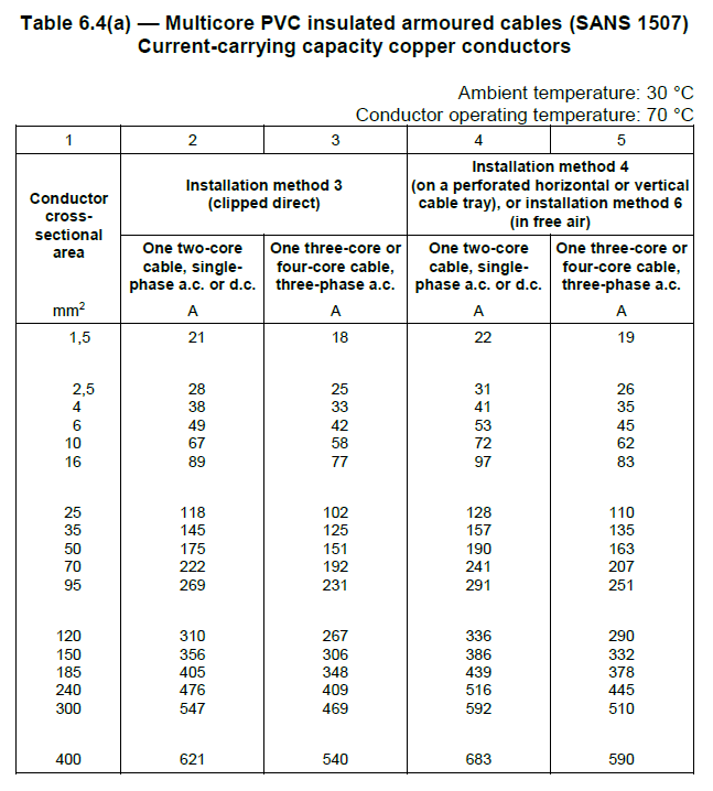
Cable sizes are sufficient to carry the current from the inverters/system. Refer to SANS 101421, Table 6.4(a) for SWA Armoured Cable
-
-
-
Does the Breaker and setting of breaker match SLD ( current and Fault rating)
-
Have the cables heatshrink been properly done?
-
Have the Breaker been labelled correctly?
-
Is there generator integration?
-
Take photo of generator tie in ( circuit breakers and wiring)
-
Is the Generator correct tie in correct?
-
Take photos of Generator integration conroller
-
Are the CT's in the correct location?
-
Where is the CTs located (Mains input/ generator input/ Automatic transfer switch output)
-
The grid consumption CTs are installed in the correct direction, ie. K or P1 towards the Grid For Solar Edge, Arrow points towards the grid
-
Take pictures of CT location, wiring and Serial Number/nameplate
-
Details of the CT's (Class/A rating/ VA rating/ 333mV or 5A output)
-
Main breaker in PV sub DB?
Main breaker in PV Sub DB
-
The Tie-In point to client Main DB has been identified
-
Take photo of Busbars/connection point (AC and Earth)
-
Take photo of Motorised breaker (connections/ trip settings/Serial Number/motorising unit)
-
Is there terminal blocks for control wiring from PV DB to main motorised breakers in Main DB
-
Is the control cable directly wired?
-
Is the connections torqued and have they been marked?
-
Current rating and setting applied
-
Is the breaker 3 or 4 Pole
-
Breaker Fault level in kA
-
AC Cables size from Main DB to PV DB motorised breaker
- 6
- 10
- 16
- 25
- 35
- 50
- 70
- 95
- 120
- 150
- 185
- 240
- 300
-
Cable sizes are sufficient to carry the current from the inverters/system. Refer to SANS 101421, Table 6.4(a) for SWA Armoured Cable
-
-
-
Does the Breaker and setting of breaker match SLD ( current and Fault rating)
-
Have the cables heatshrink been properly done?
-
Have the Breaker been labelled correctly?
-
PV DB?
PV DB
-
Any loose connections found in PV DB?
-
Is the modules connected directly to earth busbar?
-
Earth cable size
- 6
- 10
- 16
- 25
-
Evidence required
-
Earth cable type
- Bare copper
- Green Yellow
- Internal H07
- N/A
-
Evidence required
-
Type of termination on CB's and Terminals in PV DB
-
Take photo of all terminations on CB's, Terminal block, fuses and other equipment in DB
-
Is there a OOB Relay?
-
Type of Relay
-
Location of Voltage reference
-
Is there Relay voltage reference protection (type and size)
-
Are bootlace ferrules used on all connection on relay?
-
Is there terminal blocks for control wiring from OOB relay to motorised breakers
-
Are there bootlace ferrules used on the connections of the terminal blocks?
-
Is the control cable directly wired?
-
Take photo of serial numbers
-
Out of Bounds relay connection is correct and operates the MCCBs or contactors 2 in series. The OOB relay must be able to open and close the solar connection
-
Is the system smaller than 30kVA?
-
Solar DB design has been reviewed and is sized correctly for cooling etc
-
Is cooling equipment required?
-
Take photo of cooling equipment in DB
-
Is there AC SPD?
-
Type of SPD
-
Does the SPD have Fuse protection?
-
Fuze size
-
Cable size to fuse from Busbar
-
Cable size to fuse from SPD
-
Inverter Breakers
Inverter Breakers
-
Take photo of Busbars/connection point where inverter breakers are tied in to
-
Is the connections torqued and have they been marked?
-
Current rating and setting applied
-
Is the breakers 3 or 4 Pole
-
Breaker Fault level in kA
-
AC Cables size from Inverters to PV DB inverter breakers
- 6
- 10
- 16
- 25
- 35
- 50
- 70
- 95
- 120
- 150
- 185
- 240
- 300
-
Cable sizes are sufficient to carry the current from the inverters/system. Refer to SANS 101421, Table 6.4(a) for SWA Armoured Cable
-
-
-
Does the Breaker and setting of breaker match SLD ( current and Fault rating)
-
Have the cables heatshrink been properly done?
-
Have the Breakers been labelled correctly?
-
Earth cable size from earth busbar to inverters
- 6
- 10
- 16
- 25
- 35
- 50
- 70
- 95
- 120
- 150
- 185
- 240
- 300
-
Earth cable type from earth busbar to inverters
-
Inverters
Inverters
-
Take pictures of inverter Serial Numbers
-
Take Pictures of String Inputs to inverters
-
All strings are labelled on the roof and at inverter
-
Inverter mounting and spacing is as per the installation manual
-
Inverter installation manual is on site with the installation team
-
All inverters are producing energy and are communicating with the monitoring platform
-
Unused glands and holes are to be sealed with the blanks supplied in the inverter box
-
Is the inverters located outside
-
Does it require a cage and roof?
-
The inverter room has sufficient airflow and cooling
-
Inverter covers are mounted securely and all screws and glands are tightened correctly
-
Bonding, Earthing and insulation resistance test has been done and has passed before turning the power on
-
Production reading lines up with a manual measurement
-
Cable Trays
Cable trays
-
AC and DC cable trays separate?
-
Is the AC and DC cable trays mounted securely?
-
Is the AC and DC Cable tray lids mounted securely?
-
Is the AC and DC Cable trays bonded?
-
Comms Cable running separately from AC and DC conductors?
-
Cable bends are not too small in radius and are mechanically protected
-
Cable tray edges are deburred and or mechanically protected
-
Is the cuts cold galvanised?
-
Is the cuts cold galvanised?
-
Comms
Comms
-
Has the communication and metering equipment location been finalised
-
Take photo of Comms box inside and location
-
Datalogger type
-
Does the system require SCADA(>100kVA) (cape town)
-
For plants greater than 100kVA The Scada Device has been procured and the installation location is established
-
The connection between the inverters and the Scada device has been wired
-
Wiring method (RS485 or Modbus TCP)
-
Rs485 Cables used for Smartlogger/janitza/power meters/solaredge inverters ?
-
Does devices at start and end of chain have terminating resistor or switch?
-
Is the metal shielding connnected to ground on one side and disconnected on the other end?
-
Is there an Ethernet Switch?
-
Is there a power point in/nearby comms DB or in PV DB?
-
Is the installer aware that there is a need to install the techsitter meter
-
Is this a roof rental or PPA Has the Techsitter meter been ordered with the correct CTs
-
Does the monitoring system have its own router?
-
Is the router easily accessible for O&M?
-
Is the router set up and internet connectivity good?
-
Is the inverters running?
-
Inverter brand
-
IP Address of Smartlogger/Datalogger
-
IP Address of Inverters
-
IP Address of Datamanager/Datalogger
-
IP Address of Inverters
-
Is all the inverters set to static IP?
-
IP Address of Datamanager/Datalogger
-
IP Address of Inverters
-
Is all the inverters set to static IP?
-
Modbus ID's of inverters
General
-
Any additional remarks?
-
Is there boot marks on the modules
-
Is the site in neat condition and housekeeping done?
-
Is this site BUILT TO LAST


