


Title Page
-
-
TFS simPRO Reference #
-
Inspection Date
-
Site Name
-
Machine Location (use the Location Button to identify the geographic location)
-
Technician Name
-
Machine Fleet Number
Instructions
Vehicle Details
Equipment Details
-
Machine Specific Layout Reference No#
-
Work Order No#
-
Supervisor Name
-
Signature
-
Vehicle Type
-
Is this a 3, 6, 9 Service or 12 Month Service or System Recharge?
Automatic Shutdown Test (Engine Shutdown) & Inspection of Fire Detection Panel
-
**Before starting service confirm that the machine specific layout is available / present for referencing and review in order to complete the below requirements fully and correctly. Any alterations found between supplied layout and machine will require notification for immediate review**
-
Disconnect PAD from PAD lead in housing located on the side of the Automatic Actuator and install ANSUL PAD tester
- Safe to Use
- Repaired and Safe to Use
- Needs Repair but is Safe to Use
- Defective and Not Safe to Use
-
Locate the ‘End of Line’ resistor and remove cap
- Safe to Use
- Repaired and Safe to Use
- Needs Repair but is Safe to Use
- Defective and Not Safe to Use
-
Using a small flat screwdriver place a bridge across the End of Line resistor solder points and hold for 20 seconds to initiate fire system activation
- Safe to Use
- Repaired and Safe to Use
- Needs Repair but is Safe to Use
- Defective and Not Safe to Use
-
This will initiate panel alarm sequence (TFS requires 20sec/10sec actuation setup)
-
Confirm during activation sequence that all indicators and audible alarms function as intended
- Safe to Use
- Repaired and Safe to Use
- Needs Repair but is Safe to Use
- Defective and Not Safe to Use
-
Ensure machine engine shuts down and ANSUL PAD tester indicates a ‘PASS’ for the test on the LED screen
- Safe to Use
- Repaired and Safe to Use
- Needs Repair but is Safe to Use
- Defective and Not Safe to Use
-
Confirm activation sequence is correct as per Installation standards and TFS site requirements
-
Disconnect panel face from backing including internal battery
- Safe to Use
- Repaired and Safe to Use
- Needs Repair but is Safe to Use
- Defective and Not Safe to Use
-
Remove ANSUL tester and leave PAD disconnected
- Safe to Use
- Repaired and Safe to Use
- Needs Repair but is Safe to Use
- Defective and Not Safe to Use
-
Re-install ‘End of Line’ resistor cap. Make sure resistor is secured
- Safe to Use
- Repaired and Safe to Use
- Needs Repair but is Safe to Use
- Defective and Not Safe to Use
-
Make sure firewire going into the EOLR is minimal to eliminate possibility of wires twisting and touching
-
Inspect wiring and terminal strip to confirm correct installation and connection of wires
- Safe to Use
- Repaired and Safe to Use
- Needs Repair but is Safe to Use
- Defective and Not Safe to Use
-
Before re-installation of fire panel complete DOWNLOAD and save for reference
- Safe to Use
- Repaired and Safe to Use
- Needs Repair but is Safe to Use
- Defective and Not Safe to Use
-
Re-install panel face correctly to ensure secure connection with backing terminal and internal battery is connected TIGHTEN SCREWS BUT NOT OVER TIGHTEN
- Safe to Use
- Repaired and Safe to Use
- Needs Repair but is Safe to Use
- Defective and Not Safe to Use
-
Battery Date:
-
Inspect and test Isolation Switch on side of panel (ASC-N Panel Only)
- Safe to Use
- Repaired and Safe to Use
- Needs Repair but is Safe to Use
- Defective and Not Safe to Use
-
Depending on fire panel type for resetting;<br><br>*ASC-N Panels - using the ANSUL reset tool clear the memory by placing the tool over the ISOLATE LED while the DELAY button is pressed and held.<br>*MP-N Panels - using the RESET button located in the bottom right hand corner, press and hold.
-
*ASC-N Panels - using the ANSUL reset tool clear the memory by placing the tool over the ISOLATE LED while the DELAY button is pressed and held. All the LEDs and the buzzer will pulse to signify that the module reset has taken place.
- Safe to Use
- Repaired and Safe to Use
- Needs Repair but is Safe to Use
- Defective and Not Safe to Use
-
*MP-N Panels – using the RESET button located in the bottom right hand corner, press and hold. All the LEDs and the buzzer will pulse to signify that the module reset has taken place.
- Safe to Use
- Repaired and Safe to Use
- Needs Repair but is Safe to Use
- Defective and Not Safe to Use
-
Ensure fire panel has no faults and power light is flashing only by pressing and holding the delay button.
- Safe to Use
- Repaired and Safe to Use
- Needs Repair but is Safe to Use
- Defective and Not Safe to Use
-
In both cases all the LEDs and the buzzer will pulse to signify that the module reset has taken place
-
STOP – Before you continue, verify this has been double checked before proceeding.
- Safe to Use
- Repaired and Safe to Use
- Needs Repair but is Safe to Use
- Defective and Not Safe to Use
Inspection of Agent Tank(s), Hosework (¾”, ½” + ¼”) and Firewire - This is a repeatable section for multiple Agent Tanks - Complete for each Tank
-
Confirm Agent tank(s) and type(s) is located as per the machine specific layout
-
Inspect Agent tank(s), also ensuring: - Tank cylinder(s) is not damaged. - Fill cap(s) is not damaged. - ‘Tell Tale’ cap(s) are clear, and indicator(s) are not up - Nameplate and Agent band correct and not damaged. - Mounting plate and bolts are not damaged. If Agent tank(s) is damaged it will require change out immediately before fire system can be deemed functional
- Safe to Use
- Repaired and Safe to Use
- Needs Repair but is Safe to Use
- Defective and Not Safe to Use
-
*If TFS anti-tamper seal is not fitted internal inspection of Agent tank and contents is required.
-
P/T Date(s) make repeatable
-
Seal Serial No(s)#: make repeatable
-
Ensure maintenance tag(s) are installed on the Agent tank(s) and stamp number 1 (as per Aust Standards) in the applicable month
- Safe to Use
- Repaired and Safe to Use
- Needs Repair but is Safe to Use
- Defective and Not Safe to Use
-
Check burst disc(s) integrity, signs of damage and is also secured Confirming indicator arrow is facing the correct way
- Safe to Use
- Repaired and Safe to Use
- Needs Repair but is Safe to Use
- Defective and Not Safe to Use
-
Inspect the tank Actuation (LT30 / 23cft / 55cft) gas cartridge(s) for damage and rust, inspect gauge (23cft / 55cft only) to ensure its readable and charged correctly or weigh (LT30), check burst disc integrity, confirm and record pressure test date(s).
- Safe to Use
- Repaired and Safe to Use
- Needs Repair but is Safe to Use
- Defective and Not Safe to Use
-
Ensure gauges are facing outward for visual inspections
- Safe to Use
- Repaired and Safe to Use
- Needs Repair but is Safe to Use
- Defective and Not Safe to Use
-
P/T Date(s)
-
LT30 Weight(gms):
-
Disassemble Pneumatic Actuator(s); - Clean and apply lube to all O-rings (change out if required). - Check Actuator pin(s) is not damaged, bent and is sharp and straight. - Check for nicks, burrs, cross threading. - Check Expellant Gas line(s) is not blocked, or fittings rusted. - Check Pressure Relief Valve and replace if pull pin is not moving as per function.Tank
- Safe to Use
- Repaired and Safe to Use
- Needs Repair but is Safe to Use
- Defective and Not Safe to Use
Inspection of Agent Tank(s), Hosework (¾”, ½” + ¼”) and Firewire
-
Remove ¾” Distribution hoses from triple tee located at the Agent tank(s)
- Safe to Use
- Repaired and Safe to Use
- Needs Repair but is Safe to Use
- Defective and Not Safe to Use
-
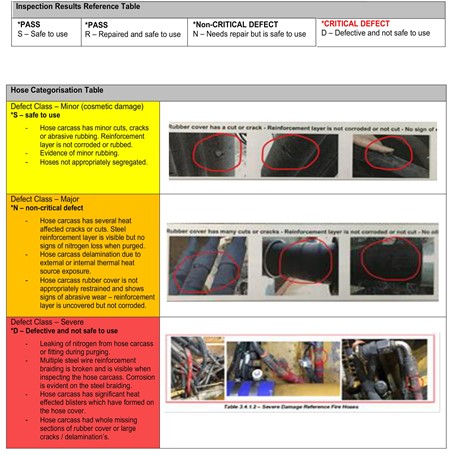
Check ¾” Distribution hoses for damage. Refer to the Hose Categorisation table on the "Instructions" page to confirm damage class Ensuring all hoses are secure and segregated from other hoses as per MDG15 Standards.
- Safe to Use
- Repaired and Safe to Use
- Needs Repair but is Safe to Use
- Defective and Not Safe to Use
-
Fit nozzle caps to all discharge nozzles (Red = DCP / Blue = LVS)
- Safe to Use
- Repaired and Safe to Use
- Needs Repair but is Safe to Use
- Defective and Not Safe to Use
-
Connect dry nitrogen line to ¾ Distribution hose’s and purge lines Standing out of the “Line of Fire” as well as communicating with others in work area before this action is started.
- Safe to Use
- Repaired and Safe to Use
- Needs Repair but is Safe to Use
- Defective and Not Safe to Use
-
Inspect and confirm free air movement through all associated discharge nozzles by placing hand at opening - Any blockages found to be cleared.
- Safe to Use
- Repaired and Safe to Use
- Needs Repair but is Safe to Use
- Defective and Not Safe to Use
-
Check nozzle openings are not obstructed, that the nozzles are correctly aimed and have not been rotated out of position.
- Safe to Use
- Repaired and Safe to Use
- Needs Repair but is Safe to Use
- Defective and Not Safe to Use
-
Using the correct machine specific layout confirm all as being inspected and ready for use, which will confirm locations of all nozzles associated with this machine and system.
*If any nozzle is unable to be either located or accessed at time of purging, please either speak with Site Supervisor for access help or note on work order as well as job sheet for further follow up by TFS planners. -
Inspect all discharge nozzle brackets are secure and tight
- Safe to Use
- Repaired and Safe to Use
- Needs Repair but is Safe to Use
- Defective and Not Safe to Use
-
Nozzle caps are refitted (Red = DCP / Blue = LVS) and in place / clean after purging of lines.
- Safe to Use
- Repaired and Safe to Use
- Needs Repair but is Safe to Use
- Defective and Not Safe to Use
-
Check all fittings and tighten where applicable
- Safe to Use
- Repaired and Safe to Use
- Needs Repair but is Safe to Use
- Defective and Not Safe to Use
-
Check ½” Distribution hoses for damage. Refer to the Hose Categorisation table on the "Instructions" page to confirm damage class Ensuring all hoses are secure and segregated from other hoses as per MDG15 Standards.
- Safe to Use
- Repaired and Safe to Use
- Needs Repair but is Safe to Use
- Defective and Not Safe to Use
-
Inspect all ANSUL non-return valves located at ¼ block manifold Confirm indicator arrow on side of valve is facing in the correct direction (into manifold) and installed correctly.
- Safe to Use
- Repaired and Safe to Use
- Needs Repair but is Safe to Use
- Defective and Not Safe to Use
-
STOP – Before you continue, verify this has been double checked before proceeding.
- Safe to Use
- Repaired and Safe to Use
- Needs Repair but is Safe to Use
- Defective and Not Safe to Use
-
Inspect Pressure Switch junction box or Deutsch plug to confirm no ingress of water or excessive dust / dirt or confirm connectors are undamaged as well as wiring connections.
- Safe to Use
- Repaired and Safe to Use
- Needs Repair but is Safe to Use
- Defective and Not Safe to Use
-
Disconnect and purge all ¼” Actuation lines ensuring that the pin(s) located in the pneumatic actuator(s) remain in the down position - this ensures that there are no leaks in the ¼” Actuation lines, non-return valves are working as designed, and fire system will function correctly. *Reset of Pressure Switch required after each ¼ line has been purged.
- Safe to Use
- Repaired and Safe to Use
- Needs Repair but is Safe to Use
- Defective and Not Safe to Use
-
Check ¼” Actuation hoses for damage. Refer to the Hose Categorisation table on the "Instructions" page to confirm damage class Ensuring all hoses are of a continuous line without bulkheads present, secure and segregated from other hoses as per MDG15 standards.
- Safe to Use
- Repaired and Safe to Use
- Needs Repair but is Safe to Use
- Defective and Not Safe to Use
-
Ensure that the TFS anti-tamper stickers are in place over the ¼” fittings once tightened. Make sure all stickers are the same colour.
-
Confirm Firewire pathway is located as per the machine specific layout
- Safe to Use
- Repaired and Safe to Use
- Needs Repair but is Safe to Use
- Defective and Not Safe to Use
-
Inspect the firewire and confirm it is routed as close to the hazard as possible. Firewire is not damaged or rub points present and is secured at intervals no longer than 30cm – 48cm apart. Ensure “best practice” is adhered to. If applicable inspect firewire junction box(s) for moisture ingress and rust. As well as correct installation of glands, conduit and shrouds. Firewire path not to be within 30cm of any areas which will become extremely hot during operation or under exhaust
- Safe to Use
- Repaired and Safe to Use
- Needs Repair but is Safe to Use
- Defective and Not Safe to Use
-
Re-assemble and re-install ALL components once service has been fully completed
Inspection of Remote Actuator(s) - This is a repeatable section. Complete for each Actuator.
-
Confirm Remote Actuator(s) are located as per the machine specific layout.
- Safe to Use
- Repaired and Safe to Use
- Needs Repair but is Safe to Use
- Defective and Not Safe to Use
-
Remove Stauff clamp(s) and LT10 Actuation cartridge(s) from Remote Actuator(s).
- Safe to Use
- Repaired and Safe to Use
- Needs Repair but is Safe to Use
- Defective and Not Safe to Use
-
Inspect Remote Actuator(s) by removing safety pin / red strike knob and depressing actuator pin, ensuring easy movement. - Clean and apply lube to all O-rings. - Check Actuator pin is not damaged, bent and is sharp and straight. - Check for nicks, burrs, cross threading.
- Safe to Use
- Repaired and Safe to Use
- Needs Repair but is Safe to Use
- Defective and Not Safe to Use
-
Ensure pull pin is in place and secure
- Safe to Use
- Repaired and Safe to Use
- Needs Repair but is Safe to Use
- Defective and Not Safe to Use
-
Place safety seal (confirm colour for month) through pull pin and around neck of actuation pin.
- Safe to Use
- Repaired and Safe to Use
- Needs Repair but is Safe to Use
- Defective and Not Safe to Use
-
Check that the red strike knob is re-connected and is not damaged or loose in any way.
- Safe to Use
- Repaired and Safe to Use
- Needs Repair but is Safe to Use
- Defective and Not Safe to Use
-
Check S bracket is not damaged in any way (impact or rust)
- Safe to Use
- Repaired and Safe to Use
- Needs Repair but is Safe to Use
- Defective and Not Safe to Use
-
Inspect Actuation cartridge(s) for damage / rust, check burst disc integrity, verify and record pressure test date(s).
- Safe to Use
- Repaired and Safe to Use
- Needs Repair but is Safe to Use
- Defective and Not Safe to Use
-
P/T Date(s)
-
Weigh Actuation cartridge(s) to ensure charged. Hand tighten cartridge(s) into Actuator once completed.
- Safe to Use
- Repaired and Safe to Use
- Needs Repair but is Safe to Use
- Defective and Not Safe to Use
-
Weight (gms)
-
Ensure maintenance tag is installed and stamp number 1 (as per Aust Standards) in the applicable month.
- Safe to Use
- Repaired and Safe to Use
- Needs Repair but is Safe to Use
- Defective and Not Safe to Use
-
Ensure appropriate signage / sticker “In-case of Fire” is in place and legible.
- Safe to Use
- Repaired and Safe to Use
- Needs Repair but is Safe to Use
- Defective and Not Safe to Use
-
Repeat the above steps for each Remote Actuater (if applicable)
-
Re-assemble and re-install ALL components once service has been fully completed.
- Safe to Use
- Repaired and Safe to Use
- Needs Repair but is Safe to Use
- Defective and Not Safe to Use
-
Ensure that the TFS anti-tamper stickers are in place over the ¼” fittings once tightened and are the same colour.
- Safe to Use
- Repaired and Safe to Use
- Needs Repair but is Safe to Use
- Defective and Not Safe to Use
Inspection of Automatic / Remote Actuator(s) - This is a repeatable section - Complete for each Actuator
-
Confirm Auto / Remote Actuator is located as per the machine specific layout.
- Safe to Use
- Repaired and Safe to Use
- Needs Repair but is Safe to Use
- Defective and Not Safe to Use
-
Inspect Automatic Actuator by removing safety pin / red strike knob and depressing actuator pin, ensuring easy movement. - Clean and apply lube to all O-rings. - Check Actuator pin is not damaged, bent and is sharp and straight. - Check for nicks, burrs, cross threading.
- Safe to Use
- Repaired and Safe to Use
- Needs Repair but is Safe to Use
- Defective and Not Safe to Use
-
Re-install PAD and confirm date of installation written on red heat shrink.
- Safe to Use
- Repaired and Safe to Use
- Needs Repair but is Safe to Use
- Defective and Not Safe to Use
-
Date:
-
Reconnect PAD to PAD lead in housing. Take care not to damage PAD or allow for disconnection when installing.
- Safe to Use
- Repaired and Safe to Use
- Needs Repair but is Safe to Use
- Defective and Not Safe to Use
-
Ensure pull pin is in place and secure.
- Safe to Use
- Repaired and Safe to Use
- Needs Repair but is Safe to Use
- Defective and Not Safe to Use
-
Place safety seal (confirm colour for month) through pull pin and around neck of actuation pin.
- Safe to Use
- Repaired and Safe to Use
- Needs Repair but is Safe to Use
- Defective and Not Safe to Use
-
Check that the red strike knob is re-connected and is not damaged or loose in any way.
- Safe to Use
- Repaired and Safe to Use
- Needs Repair but is Safe to Use
- Defective and Not Safe to Use
-
Inspect Actuation cartridge for damage / rust, check burst disc integrity, verify and record pressure test date(s).
- Safe to Use
- Repaired and Safe to Use
- Needs Repair but is Safe to Use
- Defective and Not Safe to Use
-
P/T Date
-
Weigh Actuation cartridge(s) to ensure charged. Hand tighten cartridge(s) into Actuator once completed.
- Safe to Use
- Repaired and Safe to Use
- Needs Repair but is Safe to Use
- Defective and Not Safe to Use
-
Weight (gms)
-
Ensure maintenance tag is installed and stamp number 1 (as per Aust Standards) in the applicable month.
- Safe to Use
- Repaired and Safe to Use
- Needs Repair but is Safe to Use
- Defective and Not Safe to Use
-
Ensure appropriate signage / sticker “In-case of Fire” is in place / undamaged and legible.
- Safe to Use
- Repaired and Safe to Use
- Needs Repair but is Safe to Use
- Defective and Not Safe to Use
-
Re-assemble and re-install ALL components once service has been fully completed.
- Safe to Use
- Repaired and Safe to Use
- Needs Repair but is Safe to Use
- Defective and Not Safe to Use
-
Ensure that the TFS anti-tamper stickers are in place over the ¼” fittings once tightened and are the same colour.
Inspection of Fire Extinguisher(s) - This is a repeatable section - complete for each Extinguisher
-
Confirm Fire Extinguisher(s) are located as per the machine specific layout.
- Safe to Use
- Repaired and Safe to Use
- Needs Repair but is Safe to Use
- Defective and Not Safe to Use
-
Remove the fire extinguisher(s) from the bracket(s) & check that all bracket rubbers are in place.
- Safe to Use
- Repaired and Safe to Use
- Needs Repair but is Safe to Use
- Defective and Not Safe to Use
-
Inspect fire extinguisher bracket(s) for damage.
- Safe to Use
- Repaired and Safe to Use
- Needs Repair but is Safe to Use
- Defective and Not Safe to Use
-
CHECK extinguisher is accessible.
- Safe to Use
- Repaired and Safe to Use
- Needs Repair but is Safe to Use
- Defective and Not Safe to Use
-
CHECK that the extinguisher is clean, and the operating instructions are legible.
- Safe to Use
- Repaired and Safe to Use
- Needs Repair but is Safe to Use
- Defective and Not Safe to Use
-
CHECK that the extinguisher, including any attachments, are not damaged. Refer to AS2337.1
- Safe to Use
- Repaired and Safe to Use
- Needs Repair but is Safe to Use
- Defective and Not Safe to Use
-
CHECK that the exterior of the extinguisher is not pitted or otherwise damaged by corrosion. Refer to AS2337.1
- Safe to Use
- Repaired and Safe to Use
- Needs Repair but is Safe to Use
- Defective and Not Safe to Use
-
CHECK that the hose is securely fitted, the nozzle is securely attached, the assembly is free from obstruction, and the hose shows no cracking or other signs of damage or deterioration.
- Safe to Use
- Repaired and Safe to Use
- Needs Repair but is Safe to Use
- Defective and Not Safe to Use
-
Where fitted, CHECK that the pressure indicator is legible, and registering within the operable range.
- Safe to Use
- Repaired and Safe to Use
- Needs Repair but is Safe to Use
- Defective and Not Safe to Use
-
WEIGH the extinguisher to determine that it is fully charged
- Safe to Use
- Repaired and Safe to Use
- Needs Repair but is Safe to Use
- Defective and Not Safe to Use
-
CHECK that the appropriate support bracket is securely attached to wall or another suitable feature.
- Safe to Use
- Repaired and Safe to Use
- Needs Repair but is Safe to Use
- Defective and Not Safe to Use
-
CHECK that the discharge nozzle is fitted and is not blocked or damaged
- Safe to Use
- Repaired and Safe to Use
- Needs Repair but is Safe to Use
- Defective and Not Safe to Use
-
INVERT the extinguisher and ensure that the powder remains free flowing
- Safe to Use
- Repaired and Safe to Use
- Needs Repair but is Safe to Use
- Defective and Not Safe to Use
-
Replace the anti-tamper seal (confirming correct colour for month)
- Safe to Use
- Repaired and Safe to Use
- Needs Repair but is Safe to Use
- Defective and Not Safe to Use
-
Ensure maintenance tag is installed and stamp number 1 (as per Aust Standards) in the applicable month
- Safe to Use
- Repaired and Safe to Use
- Needs Repair but is Safe to Use
- Defective and Not Safe to Use
-
Record pressure test date of extinguisher(s)
- Safe to Use
- Repaired and Safe to Use
- Needs Repair but is Safe to Use
- Defective and Not Safe to Use
-
P/T Date(s):
-
Replace fire extinguisher bag(s) where applicable and re-install into position.
- Safe to Use
- Repaired and Safe to Use
- Needs Repair but is Safe to Use
- Defective and Not Safe to Use
-
Repeat above steps for each Fire Extinguisher (if applicable)
Completion of Fire System Inspection
-
Ensure fire panel has no faults and power light is flashing only by pressing and holding the delay button.
- Safe to Use
- Repaired and Safe to Use
- Needs Repair but is Safe to Use
- Defective and Not Safe to Use
-
Re-assemble and re-install any outstanding components (including ¼, ½ + ¾ hose work / Actuation components / Agent tank components, etc).
- Safe to Use
- Repaired and Safe to Use
- Needs Repair but is Safe to Use
- Defective and Not Safe to Use
-
Photos are to be taken of critical components e.g. Automatic Actuator, ¼ block, Remote Actuator(s) and Pneumatic Actuator(s) to confirm system is functional at time of exit.
- Safe to Use
- Repaired and Safe to Use
- Needs Repair but is Safe to Use
- Defective and Not Safe to Use
-
Complete an Exit Inspection ensuring ALL components are re-installed correctly so that the fire system can function as required.
- Safe to Use
- Repaired and Safe to Use
- Needs Repair but is Safe to Use
- Defective and Not Safe to Use
-
STOP – Before you continue, verify this has been double checked before proceeding.
- Safe to Use
- Repaired and Safe to Use
- Needs Repair but is Safe to Use
- Defective and Not Safe to Use
-
Complete all relevant paperwork / sign off on work order(s) and Critical Impairment Forms.
- Safe to Use
- Repaired and Safe to Use
- Needs Repair but is Safe to Use
- Defective and Not Safe to Use
-
STOP – Has this been completed.
- Safe to Use
- Repaired and Safe to Use
- Needs Repair but is Safe to Use
- Defective and Not Safe to Use
-
If fire system is not operational, install out of service tag and inform Site Supervisor immediately!
Fire System Inspection Sign Off
-
Total Fire Solutions Technician
-
Total Fire Solutions Technician
-
Site Supervisor
Fire System Functionality Test - Repeatable Section - Complete for each Remote Actuator
-
**Before starting service confirm that the machine specific layout is available / present for referencing and review in order to complete the below requirements fully and correctly. Any alterations found between supplied layout and machine will require notification for immediate review**
-
Check function test kit provided is correct and includes the following (quantities will vary depending on machine system size); • LT5/10 Cartridges • ASC-N Battery • PAD • O-ring seals for Pneumatic(s), Automatic and Remote Actuator(s) • Safety Vent Relief Valve
- Safe to Use
- Repaired and Safe to Use
- Needs Repair but is Safe to Use
- Defective and Not Safe to Use
-
Install function test Actuation Cartridge(s) in the Automatic Actuator, Remote Actuator(s) and Pneumatic Actuator(s).
- Safe to Use
- Repaired and Safe to Use
- Needs Repair but is Safe to Use
- Defective and Not Safe to Use
-
Secure Pneumatic Actuator(s) and test Actuation Cartridge(s) with cable tie(s) to stop movement when discharged.
- Safe to Use
- Repaired and Safe to Use
- Needs Repair but is Safe to Use
- Defective and Not Safe to Use
-
Locate ‘End of Line’ resistor and remove cap.
- Safe to Use
- Repaired and Safe to Use
- Needs Repair but is Safe to Use
- Defective and Not Safe to Use
-
Using a small flat screwdriver place a bridge across the End of Line resistor solder points and hold for 20 seconds to initiate fire system activation.
- Safe to Use
- Repaired and Safe to Use
- Needs Repair but is Safe to Use
- Defective and Not Safe to Use
-
This will initiate panel alarm sequence (TFS requires 20sec/10sec Actuation setup).
- Safe to Use
- Repaired and Safe to Use
- Needs Repair but is Safe to Use
- Defective and Not Safe to Use
-
Confirm during activation sequence that all indicators and audible alarms function as intended.
- Safe to Use
- Repaired and Safe to Use
- Needs Repair but is Safe to Use
- Defective and Not Safe to Use
-
Ensure fire panel activation as per setting required.
- Safe to Use
- Repaired and Safe to Use
- Needs Repair but is Safe to Use
- Defective and Not Safe to Use
-
Confirm activation sequence is correct as per Installation standards and TFS site requirements.
- Safe to Use
- Repaired and Safe to Use
- Needs Repair but is Safe to Use
- Defective and Not Safe to Use
-
Re-install ‘End of Line’ resistor cap. Make sure resistor is secured.
- Safe to Use
- Repaired and Safe to Use
- Needs Repair but is Safe to Use
- Defective and Not Safe to Use
-
Make sure exposed firewire going into EOLR is minimal to eliminate possibility of wires twisting and touching.
- Safe to Use
- Repaired and Safe to Use
- Needs Repair but is Safe to Use
- Defective and Not Safe to Use
-
Machine shut down completed and Automatic Actuation has fired correctly.
- Safe to Use
- Repaired and Safe to Use
- Needs Repair but is Safe to Use
- Defective and Not Safe to Use
-
Disconnect panel face from backing including internal battery.
- Safe to Use
- Repaired and Safe to Use
- Needs Repair but is Safe to Use
- Defective and Not Safe to Use
-
Pull ring on Pressure Relief Valve at Pneumatic Actuator to bleed pressure and reset pressure switch.
- Safe to Use
- Repaired and Safe to Use
- Needs Repair but is Safe to Use
- Defective and Not Safe to Use
-
Activate Remote Actuator(s) and ensure LT5/10 Actuation cartridge(s) have fired. Confirm Nitrogen escapes from the Pressure Relief Valve as well as pushes and holds Actuation Pin(s) down in Pneumatic Actuator(s) during each Remote activation.
- Safe to Use
- Repaired and Safe to Use
- Needs Repair but is Safe to Use
- Defective and Not Safe to Use
-
Repeat above steps for each Remote Actuator (if applicable).
-
Remove all discharged test LT5/10 Actuation Cartridge(s), fired PAD and used Internal Battery.
- Safe to Use
- Repaired and Safe to Use
- Needs Repair but is Safe to Use
- Defective and Not Safe to Use
-
STOP – Before you continue, verify this has been double checked before proceeding.
- Safe to Use
- Repaired and Safe to Use
- Needs Repair but is Safe to Use
- Defective and Not Safe to Use
Inspection of Agent Tank(s), Hosework (¾”, ½” + ¼”) and Firewire - This section is repeatable - Complete for each Tank.
-
Confirm Agent tank(s) and type(s) is located as per the machine specific layout.
-
*Open Agent tank lid(s) removing and check / confirm Agent content(s) to ensure the following:<br>- That the correct extinguishing agent is present in the correct tank(s) i.e. DCP or LVS.
-
If agent is LVS check the following; - Confirm pH level (no less than 9 s.u) using a pH Strip. - Confirm appearance (colour and clarity) of solution.
- Safe to Use
- Repaired and Safe to Use
- Needs Repair but is Safe to Use
- Defective and Not Safe to Use
-
If agent is DCP check and confirm powder does not; - show signs of caking or moisture. - is free flowing.
- Safe to Use
- Repaired and Safe to Use
- Needs Repair but is Safe to Use
- Defective and Not Safe to Use
-
If agent is DCP check and confirm powder does not; - show signs of caking or moisture. - is free flowing.
- Safe to Use
- Repaired and Safe to Use
- Needs Repair but is Safe to Use
- Defective and Not Safe to Use
-
If contaminated Agent tank(s) will require to be changed out before fire system can be deemed functional.
- Safe to Use
- Repaired and Safe to Use
- Needs Repair but is Safe to Use
- Defective and Not Safe to Use
-
Tank Serial Number
-
Inspect Agent tank(s), also ensuring: Tank cylinder(s) is not damaged. - Fill cap(s) is not damaged. - ‘Tell Tale’ cap(s) are clear, and indicator(s) are not up - Dip tube is not damaged. - Internal wall is rust free. - Inspect threads for nicks, burrs, signs of cross threading. - Seal of tank lid is lubricated before re-securing. - Nameplate and Agent band correct and not damaged. - Mounting plate and bolts are not damaged. If Agent tank(s) is damaged it will require change out immediately before fire system can be deemed functional
- Safe to Use
- Repaired and Safe to Use
- Needs Repair but is Safe to Use
- Defective and Not Safe to Use
-
P/T Date(s):
-
*Replace TFS anti-tamper S/S seal(s) once Agent tank lid(s) re-installed and record serial number(s).
- Safe to Use
- Repaired and Safe to Use
- Needs Repair but is Safe to Use
- Defective and Not Safe to Use
-
Ensure maintenance tag(s) are installed on Agent tank(s) and stamp number 2 (as per Aust Standards) in the applicable month.
- Safe to Use
- Repaired and Safe to Use
- Needs Repair but is Safe to Use
- Defective and Not Safe to Use
-
Check burst disc(s) integrity, signs of damage and is also secured. Confirming indicator arrow is facing the correct way.
- Safe to Use
- Repaired and Safe to Use
- Needs Repair but is Safe to Use
- Defective and Not Safe to Use
-
Inspect the tank Actuation (LT30 / 23cft / 55cft) gas cartridge(s) for damage and rust, inspect gauge (23cft / 55cft only) to ensure its readable and charged correctly or weigh (LT30), check burst disc integrity, confirm and record pressure test date(s). Ensure gauges are facing outward for visual inspections
- Safe to Use
- Repaired and Safe to Use
- Needs Repair but is Safe to Use
- Defective and Not Safe to Use
-
P/T Date(s):
-
LT30 Weight(gms):
-
Check to ensure that the Pneumatic Actuator(s) on the (23cft / 55cft) nitrogen gas cartridge(s) has or have a 9/16” nipple on the top actuation port so that it cannot be confused with the ¼” Actuation hose(s) going to the Agent tank(s)
- Safe to Use
- Repaired and Safe to Use
- Needs Repair but is Safe to Use
- Defective and Not Safe to Use
-
Disassemble Pneumatic Actuator(s); - Clean and apply lube to all O-rings (change out if required). - Check Actuator pin(s) is not damaged, bent and is sharp and straight. - Check for nicks, burrs, cross threading. - Check Expellant Gas line(s) is not blocked, or fittings rusted. - Check Pressure Relief Valve and replace if pull pin is not moving as per function.
- Safe to Use
- Repaired and Safe to Use
- Needs Repair but is Safe to Use
- Defective and Not Safe to Use
Inspection of Agent Tank(s), Hosework (¾”, ½” + ¼”) and Firewire
-
Remove ¾” Distribution hoses from triple tee located at the Agent tank(s).
- Safe to Use
- Repaired and Safe to Use
- Needs Repair but is Safe to Use
- Defective and Not Safe to Use
-
Check ¾” Distribution hoses for damage. Refer to the Hose Categorisation table on page.3 to confirm damage class. Ensuring all hoses are secure and segregated from other hoses as per MDG15 Standards.
- Safe to Use
- Repaired and Safe to Use
- Needs Repair but is Safe to Use
- Defective and Not Safe to Use
-
Fit nozzle caps to all discharge nozzles (Red = DCP / Blue = LVS).
- Safe to Use
- Repaired and Safe to Use
- Needs Repair but is Safe to Use
- Defective and Not Safe to Use
-
Connect dry nitrogen line to ¾ Distribution hose’s and purge lines. Standing out of the “Line of Fire” as well as communicating with others in work area before this action is started.
- Safe to Use
- Repaired and Safe to Use
- Needs Repair but is Safe to Use
- Defective and Not Safe to Use
-
Inspect and confirm free air movement through all associated discharge nozzles by placing hand at opening - Any blockages found to be cleared.
- Safe to Use
- Repaired and Safe to Use
- Needs Repair but is Safe to Use
- Defective and Not Safe to Use
-
Check nozzle openings are not obstructed, that the nozzles are correctly aimed and have not been rotated out of position.
- Safe to Use
- Repaired and Safe to Use
- Needs Repair but is Safe to Use
- Defective and Not Safe to Use
-
Using the correct machine specific layout confirm all as being inspected and ready for use, which will confirm locations of all nozzles associated with this machine and system. *If any nozzle is unable to be either located or accessed at time of purging, please either speak with Site Supervisor for access help or note on work order as well as job sheet for further follow up by TFS planners.
- Safe to Use
- Repaired and Safe to Use
- Needs Repair but is Safe to Use
- Defective and Not Safe to Use
-
Inspect all discharge nozzle brackets are secure and tight.
- Safe to Use
- Repaired and Safe to Use
- Needs Repair but is Safe to Use
- Defective and Not Safe to Use
-
Nozzle caps are refitted (Red = DCP / Blue = LVS) and in place / clean after purging of lines.
- Safe to Use
- Repaired and Safe to Use
- Needs Repair but is Safe to Use
- Defective and Not Safe to Use
-
Check all fittings and tighten where applicable.
- Safe to Use
- Repaired and Safe to Use
- Needs Repair but is Safe to Use
- Defective and Not Safe to Use
-
Check ½” Distribution hoses for damage. Refer to the Hose Categorisation table on page.3 to confirm damage class. Ensuring all hoses are secure and segregated from other hoses as per MDG15 Standards.
- Safe to Use
- Repaired and Safe to Use
- Needs Repair but is Safe to Use
- Defective and Not Safe to Use
-
Check all fittings and tighten where applicable.
- Safe to Use
- Repaired and Safe to Use
- Needs Repair but is Safe to Use
- Defective and Not Safe to Use
-
Inspect all ANSUL non-return valves located at ¼ block manifold. Confirm indicator arrow on side of valve is facing in the correct direction (into manifold) and installed correctly.
- Safe to Use
- Repaired and Safe to Use
- Needs Repair but is Safe to Use
- Defective and Not Safe to Use
-
STOP – Before you continue, verify this has been double checked before proceeding.
- Safe to Use
- Repaired and Safe to Use
- Needs Repair but is Safe to Use
- Defective and Not Safe to Use
-
Inspect Pressure Switch junction box or Deutsch plug to confirm no ingress of water or excessive dust / dirt or confirm connectors are undamaged as well as wiring connections.
- Safe to Use
- Repaired and Safe to Use
- Needs Repair but is Safe to Use
- Defective and Not Safe to Use
-
Disconnect and purge all ¼” Actuation lines ensuring that the pin(s) located in the pneumatic actuator(s) remain in the down position - this ensures that there are no leaks in the ¼” Actuation lines, non-return valves are working as designed, and fire system will function correctly. *Reset of Pressure Switch required after each ¼ line has been purged.
- Safe to Use
- Repaired and Safe to Use
- Needs Repair but is Safe to Use
- Defective and Not Safe to Use
-
Check ¼” Actuation hoses for damage. Refer to the Hose Categorisation table on page.3 to confirm damage class. Ensuring all hoses are of a continuous line without bulkheads present, secure and segregated from other hoses as per MDG15 standards.
- Safe to Use
- Repaired and Safe to Use
- Needs Repair but is Safe to Use
- Defective and Not Safe to Use
-
Ensure that the TFS anti-tamper stickers are in place over the ¼” fittings once tightened. Make sure all stickers are the same colour.
- Safe to Use
- Repaired and Safe to Use
- Needs Repair but is Safe to Use
- Defective and Not Safe to Use
-
Confirm Firewire pathway is located as per the machine specific layout.
- Safe to Use
- Repaired and Safe to Use
- Needs Repair but is Safe to Use
- Defective and Not Safe to Use
-
Inspect the firewire and confirm it is routed as close to the hazard as possible. Firewire is not damaged or rub points present and is secured at intervals no longer than 30cm – 48cm apart. Ensure “best practice” is adhered to. If applicable inspect firewire junction box(s) for moisture ingress and rust. As well as correct installation of glands, conduit and shrouds. Firewire path not to be within 30cm of any areas which will become extremely hot during operation or under exhaust
- Safe to Use
- Repaired and Safe to Use
- Needs Repair but is Safe to Use
- Defective and Not Safe to Use
-
Re-assemble and re-install ALL components once service has been fully completed.
- Safe to Use
- Repaired and Safe to Use
- Needs Repair but is Safe to Use
- Defective and Not Safe to Use
Inspection of Remote Actuator(s) - This is a repeatable section. Complete for each Actuator.
-
Confirm Remote Actuator(s) are located as per the machine specific layout.
- Safe to Use
- Repaired and Safe to Use
- Needs Repair but is Safe to Use
- Defective and Not Safe to Use
-
Remove Stauff clamp(s) and LT10 Actuation cartridge(s) from Remote Actuator(s).
- Safe to Use
- Repaired and Safe to Use
- Needs Repair but is Safe to Use
- Defective and Not Safe to Use
-
Inspect Remote Actuator(s) by removing safety pin / red strike knob and depressing actuator pin, ensuring easy movement. - Clean and apply lube to all O-rings. - Check Actuator pin is not damaged, bent and is sharp and straight. - Check for nicks, burrs, cross threading.
- Safe to Use
- Repaired and Safe to Use
- Needs Repair but is Safe to Use
- Defective and Not Safe to Use
-
Ensure pull pin is in place and secure
- Safe to Use
- Repaired and Safe to Use
- Needs Repair but is Safe to Use
- Defective and Not Safe to Use
-
Place safety seal (confirm colour for month) through pull pin and around neck of actuation pin.
- Safe to Use
- Repaired and Safe to Use
- Needs Repair but is Safe to Use
- Defective and Not Safe to Use
-
Check that the red strike knob is re-connected and is not damaged or loose in any way.
- Safe to Use
- Repaired and Safe to Use
- Needs Repair but is Safe to Use
- Defective and Not Safe to Use
-
Check S bracket is not damaged in any way (impact or rust)
- Safe to Use
- Repaired and Safe to Use
- Needs Repair but is Safe to Use
- Defective and Not Safe to Use
-
Inspect Actuation cartridge(s) for damage / rust, check burst disc integrity, verify and record pressure test date(s).
- Safe to Use
- Repaired and Safe to Use
- Needs Repair but is Safe to Use
- Defective and Not Safe to Use
-
P/T Date(s)
-
Weigh Actuation cartridge(s) to ensure charged. Hand tighten cartridge(s) into Actuator once completed.
- Safe to Use
- Repaired and Safe to Use
- Needs Repair but is Safe to Use
- Defective and Not Safe to Use
-
Weight (gms)
-
Ensure maintenance tag is installed and stamp number 1 (as per Aust Standards) in the applicable month.
- Safe to Use
- Repaired and Safe to Use
- Needs Repair but is Safe to Use
- Defective and Not Safe to Use
-
Ensure appropriate signage / sticker “In-case of Fire” is in place and legible.
- Safe to Use
- Repaired and Safe to Use
- Needs Repair but is Safe to Use
- Defective and Not Safe to Use
-
Repeat the above steps for each Remote Actuater (if applicable)
-
Re-assemble and re-install ALL components once service has been fully completed.
- Safe to Use
- Repaired and Safe to Use
- Needs Repair but is Safe to Use
- Defective and Not Safe to Use
-
Ensure that the TFS anti-tamper stickers are in place over the ¼” fittings once tightened and are the same colour.
- Safe to Use
- Repaired and Safe to Use
- Needs Repair but is Safe to Use
- Defective and Not Safe to Use
Inspection of Automatic / Remote Actuator(s) - This is a repeatable section - Complete for each Actuator
-
Confirm Auto / Remote Actuator is located as per the machine specific layout.
- Safe to Use
- Repaired and Safe to Use
- Needs Repair but is Safe to Use
- Defective and Not Safe to Use
-
Inspect Automatic Actuator by removing safety pin / red strike knob and depressing actuator pin, ensuring easy movement. - Clean and apply lube to all O-rings. - Check Actuator pin is not damaged, bent and is sharp and straight. - Check for nicks, burrs, cross threading.
- Safe to Use
- Repaired and Safe to Use
- Needs Repair but is Safe to Use
- Defective and Not Safe to Use
-
Re-install PAD and confirm date of installation written on red heat shrink.
- Safe to Use
- Repaired and Safe to Use
- Needs Repair but is Safe to Use
- Defective and Not Safe to Use
-
Date:
-
Reconnect PAD to PAD lead in housing. Take care not to damage PAD or allow for disconnection when installing.
- Safe to Use
- Repaired and Safe to Use
- Needs Repair but is Safe to Use
- Defective and Not Safe to Use
-
Ensure pull pin is in place and secure.
- Safe to Use
- Repaired and Safe to Use
- Needs Repair but is Safe to Use
- Defective and Not Safe to Use
-
Place safety seal (confirm colour for month) through pull pin and around neck of actuation pin.
- Safe to Use
- Repaired and Safe to Use
- Needs Repair but is Safe to Use
- Defective and Not Safe to Use
-
Check that the red strike knob is re-connected and is not damaged or loose in any way.
- Safe to Use
- Repaired and Safe to Use
- Needs Repair but is Safe to Use
- Defective and Not Safe to Use
-
Inspect Actuation cartridge for damage / rust, check burst disc integrity, verify and record pressure test date(s).
- Safe to Use
- Repaired and Safe to Use
- Needs Repair but is Safe to Use
- Defective and Not Safe to Use
-
P/T Date
-
Weigh Actuation cartridge(s) to ensure charged. Hand tighten cartridge(s) into Actuator once completed.
- Safe to Use
- Repaired and Safe to Use
- Needs Repair but is Safe to Use
- Defective and Not Safe to Use
-
Weight (gms)
-
Ensure maintenance tag is installed and stamp number 1 (as per Aust Standards) in the applicable month.
- Safe to Use
- Repaired and Safe to Use
- Needs Repair but is Safe to Use
- Defective and Not Safe to Use
-
Ensure appropriate signage / sticker “In-case of Fire” is in place / undamaged and legible.
- Safe to Use
- Repaired and Safe to Use
- Needs Repair but is Safe to Use
- Defective and Not Safe to Use
-
Re-assemble and re-install ALL components once service has been fully completed.
- Safe to Use
- Repaired and Safe to Use
- Needs Repair but is Safe to Use
- Defective and Not Safe to Use
-
Ensure that the TFS anti-tamper stickers are in place over the ¼” fittings once tightened and are the same colour.
Inspection of Fire Extinguisher(s) - This is a repeatable section - complete for each Extinguisher
-
Confirm Fire Extinguisher(s) are located as per the machine specific layout.
-
Remove the fire extinguisher(s) from the bracket(s) & check that all bracket rubbers are in place.
- Safe to Use
- Repaired and Safe to Use
- Needs Repair but is Safe to Use
- Defective and Not Safe to Use
-
Inspect fire extinguisher bracket(s) for damage.
- Safe to Use
- Repaired and Safe to Use
- Needs Repair but is Safe to Use
- Defective and Not Safe to Use
-
CHECK extinguisher is accessible.
- Safe to Use
- Repaired and Safe to Use
- Needs Repair but is Safe to Use
- Defective and Not Safe to Use
-
CHECK that the extinguisher is clean, and the operating instructions are legible.
- Safe to Use
- Repaired and Safe to Use
- Needs Repair but is Safe to Use
- Defective and Not Safe to Use
-
CHECK that the extinguisher, including any attachments, are not damaged. Refer to AS2337.1
- Safe to Use
- Repaired and Safe to Use
- Needs Repair but is Safe to Use
- Defective and Not Safe to Use
-
CHECK that the exterior of the extinguisher is not pitted or otherwise damaged by corrosion. Refer to AS2337.1
- Safe to Use
- Repaired and Safe to Use
- Needs Repair but is Safe to Use
- Defective and Not Safe to Use
-
CHECK that the hose is securely fitted, the nozzle is securely attached, the assembly is free from obstruction, and the hose shows no cracking or other signs of damage or deterioration.
- Safe to Use
- Repaired and Safe to Use
- Needs Repair but is Safe to Use
- Defective and Not Safe to Use
-
Where fitted, CHECK that the pressure indicator is legible, and registering within the operable range.
- Safe to Use
- Repaired and Safe to Use
- Needs Repair but is Safe to Use
- Defective and Not Safe to Use
-
WEIGH the extinguisher to determine that it is fully charged
- Safe to Use
- Repaired and Safe to Use
- Needs Repair but is Safe to Use
- Defective and Not Safe to Use
-
CHECK that the appropriate support bracket is securely attached to wall or another suitable feature.
- Safe to Use
- Repaired and Safe to Use
- Needs Repair but is Safe to Use
- Defective and Not Safe to Use
-
CHECK that the discharge nozzle is fitted and is not blocked or damaged
- Safe to Use
- Repaired and Safe to Use
- Needs Repair but is Safe to Use
- Defective and Not Safe to Use
-
INVERT the extinguisher and ensure that the powder remains free flowing
- Safe to Use
- Repaired and Safe to Use
- Needs Repair but is Safe to Use
- Defective and Not Safe to Use
-
Replace the anti-tamper seal (confirming correct colour for month)
- Safe to Use
- Repaired and Safe to Use
- Needs Repair but is Safe to Use
- Defective and Not Safe to Use
-
Ensure maintenance tag is installed and stamp number 1 (as per Aust Standards) in the applicable month
- Safe to Use
- Repaired and Safe to Use
- Needs Repair but is Safe to Use
- Defective and Not Safe to Use
-
Record pressure test date of extinguisher(s)
- Safe to Use
- Repaired and Safe to Use
- Needs Repair but is Safe to Use
- Defective and Not Safe to Use
-
P/T Date(s):
-
Replace fire extinguisher bag(s) where applicable and re-install into position.
- Safe to Use
- Repaired and Safe to Use
- Needs Repair but is Safe to Use
- Defective and Not Safe to Use
-
Repeat above steps for each Fire Extinguisher (if applicable)
Fire Detection Panel
-
Confirm Fire Panel is located as per the machine specific layout.
- Safe to Use
- Repaired and Safe to Use
- Needs Repair but is Safe to Use
- Defective and Not Safe to Use
-
Check panel face is clean, undamaged, labels visible and accessible.
- Safe to Use
- Repaired and Safe to Use
- Needs Repair but is Safe to Use
- Defective and Not Safe to Use
-
Check panel backing is undamaged and mounting bracket secure and undamaged.
- Safe to Use
- Repaired and Safe to Use
- Needs Repair but is Safe to Use
- Defective and Not Safe to Use
-
Install NEW Internal Battery with written date.
- Safe to Use
- Repaired and Safe to Use
- Needs Repair but is Safe to Use
- Defective and Not Safe to Use
-
Date:
-
Ensure program switches are correctly positioned as per installation document and TFS site requirements. All wiring and terminations are secured and not damaged.
- Safe to Use
- Repaired and Safe to Use
- Needs Repair but is Safe to Use
- Defective and Not Safe to Use
-
Inspect wiring and terminal strip to confirm correct installation and connection of wires.
- Safe to Use
- Repaired and Safe to Use
- Needs Repair but is Safe to Use
- Defective and Not Safe to Use
-
Before re-installation of fire panel complete DOWNLOAD and save for reference.
- Safe to Use
- Repaired and Safe to Use
- Needs Repair but is Safe to Use
- Defective and Not Safe to Use
-
Re-install panel face correctly to ensure secure connection with backing terminal and internal battery is connected - Tighten screws but not overtighten.
- Safe to Use
- Repaired and Safe to Use
- Needs Repair but is Safe to Use
- Defective and Not Safe to Use
-
Inspect and test Isolation Switch on side of panel (ASC-N panels only).
- Safe to Use
- Repaired and Safe to Use
- Needs Repair but is Safe to Use
- Defective and Not Safe to Use
-
Depending on fire panel type for resetting;<br><br>*ASC-N Panels - using the ANSUL reset tool clear the memory by placing the tool over the ISOLATE LED while the DELAY button is pressed and held.<br>*MP-N Panels - using the RESET button located in the bottom right hand corner, press and hold.
-
*ASC-N Panels - using the ANSUL reset tool clear the memory by placing the tool over the ISOLATE LED while the DELAY button is pressed and held. All the LEDs and the buzzer will pulse to signify that the module reset has taken place.x
- Safe to Use
- Repaired and Safe to Use
- Needs Repair but is Safe to Use
- Defective and Not Safe to Use
-
*MP-N Panels – using the RESET button located in the bottom right hand corner, press and hold. All the LEDs and the buzzer will pulse to signify that the module reset has taken place.
- Safe to Use
- Repaired and Safe to Use
- Needs Repair but is Safe to Use
- Defective and Not Safe to Use
Completion of Fire System Inspection
-
Ensure fire panel has no faults and power light is flashing only by pressing and holding the delay button.
- Safe to Use
- Repaired and Safe to Use
- Needs Repair but is Safe to Use
- Defective and Not Safe to Use
-
Re-assemble and re-install any outstanding components (including ¼, ½ + ¾ hose work / Actuation components / Agent tank components, etc).
- Safe to Use
- Repaired and Safe to Use
- Needs Repair but is Safe to Use
- Defective and Not Safe to Use
-
Photos are to be taken of critical components e.g. Automatic Actuator, ¼ block, Remote Actuator(s) and Pneumatic Actuator(s) to confirm system is functional at time of exit.
- Safe to Use
- Repaired and Safe to Use
- Needs Repair but is Safe to Use
- Defective and Not Safe to Use
-
Complete an Exit Inspection ensuring ALL components are re-installed correctly so that the fire system can function as required.
- Safe to Use
- Repaired and Safe to Use
- Needs Repair but is Safe to Use
- Defective and Not Safe to Use
-
STOP – Before you continue, verify this has been double checked before proceeding.
- Safe to Use
- Repaired and Safe to Use
- Needs Repair but is Safe to Use
- Defective and Not Safe to Use
-
Complete all relevant paperwork / sign off on work order(s) and Critical Impairment Forms.
- Safe to Use
- Repaired and Safe to Use
- Needs Repair but is Safe to Use
- Defective and Not Safe to Use
-
STOP – Has this been completed.
- Safe to Use
- Repaired and Safe to Use
- Needs Repair but is Safe to Use
- Defective and Not Safe to Use
-
If fire system is not operational, install out of service tag and inform Site Supervisor immediately!
Fire System Inspection Sign Off
-
Total Fire Solutions Technician
-
Total Fire Solutions Technician
-
Site Supervisor
Inspection of Fire System to confirm Discharge Cause (Automatic Actuation Only)
-
Confirm reason for Activation was due to fire. If unable, give detailed description of why fire system has activated using Discharge Report form. *If Activation has occurred due to system issues other than fire this will need to be confirmed and diagnosed.
-
Complete DOWNLOAD of fire panel and save for reference.
- Safe to Use
- Repaired and Safe to Use
- Needs Repair but is Safe to Use
- Defective and Not Safe to Use
-
Inspect firewire and confirm location of fire and damage.
- Safe to Use
- Repaired and Safe to Use
- Needs Repair but is Safe to Use
- Defective and Not Safe to Use
-
Confirm cause of damage (notes in Simpro to be completed) and take photos to confirm for reference and reporting.
- Safe to Use
- Repaired and Safe to Use
- Needs Repair but is Safe to Use
- Defective and Not Safe to Use
-
STOP - Have photos been taken for referencing to notes
- Safe to Use
- Repaired and Safe to Use
- Needs Repair but is Safe to Use
- Defective and Not Safe to Use
-
Replace all damaged firewire.
- Safe to Use
- Repaired and Safe to Use
- Needs Repair but is Safe to Use
- Defective and Not Safe to Use
-
Confirm if damage has occurred to any other parts of the fire system (hosework / pressure switch wiring, etc) and organise for repairs to be completed.
- Safe to Use
- Repaired and Safe to Use
- Needs Repair but is Safe to Use
- Defective and Not Safe to Use
-
*If repairs need to be revisited then an Exception Report is to be completed and handed into TFS Planners for immediate action.
- Safe to Use
- Repaired and Safe to Use
- Needs Repair but is Safe to Use
- Defective and Not Safe to Use
Inspection of Fire System to Confirm Discharge Cause (Manual Activation Only)
-
Confirm reason for Activation (notes in Simpro to be completed) as well as take photos for reference and reporting.
- Safe to Use
- Repaired and Safe to Use
- Needs Repair but is Safe to Use
- Defective and Not Safe to Use
-
STOP - Have photos been taken for referencing to notes
- Safe to Use
- Repaired and Safe to Use
- Needs Repair but is Safe to Use
- Defective and Not Safe to Use
-
Complete DOWNLOAD of fire panel and save for reference.
- Safe to Use
- Repaired and Safe to Use
- Needs Repair but is Safe to Use
- Defective and Not Safe to Use
-
Confirm if damage has occurred to any parts of the fire system (hosework / pressure switch wiring, etc) and organise for repairs to be completed.
- Safe to Use
- Repaired and Safe to Use
- Needs Repair but is Safe to Use
- Defective and Not Safe to Use
-
*If repairs need to be revisited then an Exception Report is to be completed and handed into TFS Planners for immediate action.
- Safe to Use
- Repaired and Safe to Use
- Needs Repair but is Safe to Use
- Defective and Not Safe to Use
Purging of ¾ + ½ Distribution Hose work
-
Remove ¾” Distribution hoses from triple tee located at the Agent tank(s).
-
Connect dry nitrogen line to ¾ Distribution hoses and purge lines including ½ Distribution hoses. *Note: - Standing out of the “Line of Fire” as well as communicating with others in work area before this action is started
- Safe to Use
- Repaired and Safe to Use
- Needs Repair but is Safe to Use
- Defective and Not Safe to Use
-
Inspect and confirm free air movement through all associated discharge nozzles - Any blockages found to be cleared. Refer to machine nozzle layout sheet to confirm all nozzles are located and checked.
- Safe to Use
- Repaired and Safe to Use
- Needs Repair but is Safe to Use
- Defective and Not Safe to Use
-
Using the correct machine specific layout confirm all as being inspected and ready for use, which will confirm locations of all nozzles associated with this machine and system.
- Safe to Use
- Repaired and Safe to Use
- Needs Repair but is Safe to Use
- Defective and Not Safe to Use
-
*If any nozzle is unable to be either located or accessed at time of purging, please either speak with Site Supervisor for access help or note on work order as well as job sheet for further follow up by TFS planners.
- Safe to Use
- Repaired and Safe to Use
- Needs Repair but is Safe to Use
- Defective and Not Safe to Use
-
Inspect all discharge nozzle brackets are secure and tight, and nozzle caps are refitted (Red = DCP / Blue = LVS) after purging lines.
- Safe to Use
- Repaired and Safe to Use
- Needs Repair but is Safe to Use
- Defective and Not Safe to Use
-
Repeat above steps for each ¾” Distribution hose.
-
Reconnect all ¾” Distribution hoses.
- Safe to Use
- Repaired and Safe to Use
- Needs Repair but is Safe to Use
- Defective and Not Safe to Use
Recharging of Agent into Tank(s) and Additional Component Checks
-
Remove discharged LT30/23cft/55cft gas cartridge(s) and replace with recharged unit(s).
- Safe to Use
- Repaired and Safe to Use
- Needs Repair but is Safe to Use
- Defective and Not Safe to Use
-
LT30 Weight (gms):
-
Change out Pneumatic Actuator pin(s)
- Safe to Use
- Repaired and Safe to Use
- Needs Repair but is Safe to Use
- Defective and Not Safe to Use
-
Reconnect Pneumatic Actuator(s) and ¼ Actuation hose(s).
- Safe to Use
- Repaired and Safe to Use
- Needs Repair but is Safe to Use
- Defective and Not Safe to Use
-
Ensure that the TFS anti-tamper stickers are in place over the ¼” fittings once tightened. Make sure all stickers are the same colour.
-
Open Agent tank lid(s) removing TFS Anti-tamper S/S seal(s) to ensure the following: - All Agent (DCP / LVS) has been expelled during discharge - Dip tube is not damaged in any way. - Internal wall is rust free. If a high quantity of agent is still present investigate and confirm why before refilling.
- Safe to Use
- Repaired and Safe to Use
- Needs Repair but is Safe to Use
- Defective and Not Safe to Use
-
If a high quantity of agent is still present investigate and confirm why before refilling. (please add Notes explaining the any discovered issues)
- Safe to Use
- Repaired and Safe to Use
- Needs Repair but is Safe to Use
- Defective and Not Safe to Use
-
Replace Agent tank burst disc(s). Confirming indicator arrow is facing the correct way.
- Safe to Use
- Repaired and Safe to Use
- Needs Repair but is Safe to Use
- Defective and Not Safe to Use
-
Refill Agent tank(s) with the correct amount of agent – as specified in the below table; 30lb DCP tank = 11.3kg (25lb) of agent. 125lb DCP tank = 50.8kg (112lb) of agent. 250lb DCP tank = 102.1kg (225lb) of agent. 15gal LVS tank = 56.8ltr (15gal) of agent. 30gal LVS tank = 113.6ltr (30gal) of agent.
- Safe to Use
- Repaired and Safe to Use
- Needs Repair but is Safe to Use
- Defective and Not Safe to Use
-
Before re-sealing Agent tank(s) ensure the following: - Seal of tank lid is lubricated before re-securing. - ‘Tell Tale’ cap(s) are clear, and indicator(s) are not up.
- Safe to Use
- Repaired and Safe to Use
- Needs Repair but is Safe to Use
- Defective and Not Safe to Use
-
Replace TFS anti-tamper S/S seal(s) once Agent tank lid(s) are re-installed.
- Safe to Use
- Repaired and Safe to Use
- Needs Repair but is Safe to Use
- Defective and Not Safe to Use
-
Ensure maintenance tag is installed and stamp number 5 (as per Aust Standards) in the applicable month.
- Safe to Use
- Repaired and Safe to Use
- Needs Repair but is Safe to Use
- Defective and Not Safe to Use
-
*Note - if Agent tank(s) is damaged it will require change out immediately before fire system can be deemed functional
Inspection of Fire Extinguisher(s)
-
Replace fire extinguisher(s) if used during incident.
- Safe to Use
- Repaired and Safe to Use
- Needs Repair but is Safe to Use
- Defective and Not Safe to Use
-
Replace the anti-tamper seal (confirming correct colour for month).
- Safe to Use
- Repaired and Safe to Use
- Needs Repair but is Safe to Use
- Defective and Not Safe to Use
-
Ensure maintenance tag is installed and stamp number 2 (as per Aust Standards) in the applicable month.
- Safe to Use
- Repaired and Safe to Use
- Needs Repair but is Safe to Use
- Defective and Not Safe to Use
-
Replace fire extinguisher bag(s) and re-install into bracket(s), ensuring the correct operation of the bracket buckle - Tighten strap and secure.
- Safe to Use
- Repaired and Safe to Use
- Needs Repair but is Safe to Use
- Defective and Not Safe to Use
Restoration of Fire System
-
Ensure fire panel has no faults and power light is flashing only by pressing and holding the delay button.
-
Replace internal battery and record installation date (Automatic Actuation only).
-
Battery Installation Date
-
Install new PAD with date of installation written on red heat shrink (Automatic Activation only).
-
PAD Installation Date
-
Reconnect PAD to PAD lead in housing (Automatic Actuation only).
-
Depending on fire panel type for resetting;<br><br>*ASC-N Panels - using the ANSUL reset tool clear the memory by placing the tool over the ISOLATE LED while the DELAY button is pressed and held.<br>*MP-N Panels - using the RESET button located in the bottom right hand corner, press and hold.
-
*ASC-N Panels - using the ANSUL reset tool clear the memory by placing the tool over the ISOLATE LED while the DELAY button is pressed and held. All the LEDs and the buzzer will pulse to signify that the module reset has taken place.
- Safe to Use
- Repaired and Safe to Use
- Needs Repair but is Safe to Use
- Defective and Not Safe to Use
-
*MP-N Panels – using the RESET button located in the bottom right hand corner, press and hold. All the LEDs and the buzzer will pulse to signify that the module reset has taken place.
- Safe to Use
- Repaired and Safe to Use
- Needs Repair but is Safe to Use
- Defective and Not Safe to Use
-
Ensure no faults present and power light is flashing only by pressing and holding the delay button.
- Safe to Use
- Repaired and Safe to Use
- Needs Repair but is Safe to Use
- Defective and Not Safe to Use
-
Before re-installing the LT10 Actuation cartridge into the Automatic Actuator inspect fire system to confirm no faults are present that may activate system and correct if required.
-
Re-assemble and re-install any outstanding components (including ¼, ½ + ¾ hose work / Actuation components / Agent tank components, etc).
- Safe to Use
- Repaired and Safe to Use
- Needs Repair but is Safe to Use
- Defective and Not Safe to Use
-
Photos are to be taken of critical components e.g. Automatic Actuator, ¼ block, Remote Actuator(s) and Pneumatic Actuator(s) to confirm system is functional at time of exit.
-
Complete an Exit Inspection ensuring ALL components are re-installed correctly so that the fire system can function as required.
- Safe to Use
- Repaired and Safe to Use
- Needs Repair but is Safe to Use
- Defective and Not Safe to Use
-
STOP – Before you continue, verify this has been double checked before proceeding.
- Safe to Use
- Repaired and Safe to Use
- Needs Repair but is Safe to Use
- Defective and Not Safe to Use
-
Complete all relevant paperwork / sign off on work order(s) and Critical Impairment Forms.
- Safe to Use
- Repaired and Safe to Use
- Needs Repair but is Safe to Use
- Defective and Not Safe to Use
-
STOP – Has all the paperwork, including the work orders and Critical Impairment Forms been completed.
- Safe to Use
- Repaired and Safe to Use
- Needs Repair but is Safe to Use
- Defective and Not Safe to Use
-
If fire system is not operational, install out of service tag and inform Site Supervisor immediately!
Recharge Customer Sign Off
-
Technician Signature
-
Technician Signature
-
Customer Supervisor Signature
-
Is this a 3, 6, 9 Service or 12 Month Service or System Recharge?
Automatic Shutdown Test (Engine Shutdown) & Inspection of Fire Detection Panel
-
**Before starting service confirm that the machine specific layout is available / present for referencing and review in order to complete the below requirements fully and correctly. Any alterations found between supplied layout and machine will require notification for immediate review**
-
Disconnect PAD from PAD lead in housing located on the side of the Automatic Actuator and install ANSUL PAD tester
- Safe to Use
- Repaired and Safe to Use
- Needs Repair but is Safe to Use
- Defective and Not Safe to Use
-
Locate the ‘End of Line’ resistor and remove cap
- Safe to Use
- Repaired and Safe to Use
- Needs Repair but is Safe to Use
- Defective and Not Safe to Use
-
Using a small flat screwdriver place a bridge across the End of Line resistor solder points and hold for 20 seconds to initiate fire system activation
- Safe to Use
- Repaired and Safe to Use
- Needs Repair but is Safe to Use
- Defective and Not Safe to Use
-
This will initiate panel alarm sequence (TFS requires 20sec/10sec actuation setup)
-
Confirm during activation sequence that all indicators and audible alarms function as intended
- Safe to Use
- Repaired and Safe to Use
- Needs Repair but is Safe to Use
- Defective and Not Safe to Use
-
Ensure machine engine shuts down and ANSUL PAD tester indicates a ‘PASS’ for the test on the LED screen
- Safe to Use
- Repaired and Safe to Use
- Needs Repair but is Safe to Use
- Defective and Not Safe to Use
-
Confirm activation sequence is correct as per Installation standards and TFS site requirements
-
Disconnect panel face from backing including internal battery
- Safe to Use
- Repaired and Safe to Use
- Needs Repair but is Safe to Use
- Defective and Not Safe to Use
-
Remove ANSUL tester and leave PAD disconnected
- Safe to Use
- Repaired and Safe to Use
- Needs Repair but is Safe to Use
- Defective and Not Safe to Use
-
Re-install ‘End of Line’ resistor cap. Make sure resistor is secured
- Safe to Use
- Repaired and Safe to Use
- Needs Repair but is Safe to Use
- Defective and Not Safe to Use
-
Make sure firewire going into the EOLR is minimal to eliminate possibility of wires twisting and touching
-
Inspect wiring and terminal strip to confirm correct installation and connection of wires
- Safe to Use
- Repaired and Safe to Use
- Needs Repair but is Safe to Use
- Defective and Not Safe to Use
-
Before re-installation of fire panel complete DOWNLOAD and save for reference
- Safe to Use
- Repaired and Safe to Use
- Needs Repair but is Safe to Use
- Defective and Not Safe to Use
-
Re-install panel face correctly to ensure secure connection with backing terminal and internal battery is connected TIGHTEN SCREWS BUT NOT OVER TIGHTEN
- Safe to Use
- Repaired and Safe to Use
- Needs Repair but is Safe to Use
- Defective and Not Safe to Use
-
Battery Date:
-
Inspect and test Isolation Switch on side of panel (ASC-N Panel Only)
- Safe to Use
- Repaired and Safe to Use
- Needs Repair but is Safe to Use
- Defective and Not Safe to Use
-
Depending on fire panel type for resetting;<br><br>*ASC-N Panels - using the ANSUL reset tool clear the memory by placing the tool over the ISOLATE LED while the DELAY button is pressed and held.<br>*MP-N Panels - using the RESET button located in the bottom right hand corner, press and hold.
-
*ASC-N Panels - using the ANSUL reset tool clear the memory by placing the tool over the ISOLATE LED while the DELAY button is pressed and held. All the LEDs and the buzzer will pulse to signify that the module reset has taken place.
- Safe to Use
- Repaired and Safe to Use
- Needs Repair but is Safe to Use
- Defective and Not Safe to Use
-
*MP-N Panels – using the RESET button located in the bottom right hand corner, press and hold. All the LEDs and the buzzer will pulse to signify that the module reset has taken place.
- Safe to Use
- Repaired and Safe to Use
- Needs Repair but is Safe to Use
- Defective and Not Safe to Use
-
Ensure fire panel has no faults and power light is flashing only by pressing and holding the delay button.
- Safe to Use
- Repaired and Safe to Use
- Needs Repair but is Safe to Use
- Defective and Not Safe to Use
-
In both cases all the LEDs and the buzzer will pulse to signify that the module reset has taken place
-
STOP – Before you continue, verify this has been double checked before proceeding.
- Safe to Use
- Repaired and Safe to Use
- Needs Repair but is Safe to Use
- Defective and Not Safe to Use
Inspection of Agent Tank(s), Hosework (¾”, ½” + ¼”) and Firewire - This is a repeatable section for multiple Agent Tanks - Complete for each Tank
-
Confirm Agent tank(s) and type(s) is located as per the machine specific layout
-
Inspect Agent tank(s), also ensuring: - Tank cylinder(s) is not damaged. - Fill cap(s) is not damaged. - ‘Tell Tale’ cap(s) are clear, and indicator(s) are not up - Nameplate and Agent band correct and not damaged. - Mounting plate and bolts are not damaged. If Agent tank(s) is damaged it will require change out immediately before fire system can be deemed functional
- Safe to Use
- Repaired and Safe to Use
- Needs Repair but is Safe to Use
- Defective and Not Safe to Use
-
*If TFS anti-tamper seal is not fitted internal inspection of Agent tank and contents is required.
-
P/T Date(s)
-
Seal Serial No(s)#:
-
Ensure maintenance tag(s) are installed on the Agent tank(s) and stamp number 1 (as per Aust Standards) in the applicable month
- Safe to Use
- Repaired and Safe to Use
- Needs Repair but is Safe to Use
- Defective and Not Safe to Use
-
Check burst disc(s) integrity, signs of damage and is also secured Confirming indicator arrow is facing the correct way
- Safe to Use
- Repaired and Safe to Use
- Needs Repair but is Safe to Use
- Defective and Not Safe to Use
-
Inspect the tank Actuation (LT30 / 23cft / 55cft) gas cartridge(s) for damage and rust, inspect gauge (23cft / 55cft only) to ensure its readable and charged correctly or weigh (LT30), check burst disc integrity, confirm and record pressure test date(s).
- Safe to Use
- Repaired and Safe to Use
- Needs Repair but is Safe to Use
- Defective and Not Safe to Use
-
Ensure gauges are facing outward for visual inspections
- Safe to Use
- Repaired and Safe to Use
- Needs Repair but is Safe to Use
- Defective and Not Safe to Use
-
P/T Date(s)
-
LT30 Weight(gms):
-
Disassemble Pneumatic Actuator(s); - Clean and apply lube to all O-rings (change out if required). - Check Actuator pin(s) is not damaged, bent and is sharp and straight. - Check for nicks, burrs, cross threading. - Check Expellant Gas line(s) is not blocked, or fittings rusted. - Check Pressure Relief Valve and replace if pull pin is not moving as per function.Tank
- Safe to Use
- Repaired and Safe to Use
- Needs Repair but is Safe to Use
- Defective and Not Safe to Use
Inspection of Agent Tank(s), Hosework (¾”, ½” + ¼”) and Firewire
-
Remove ¾” Distribution hoses from triple tee located at the Agent tank(s)
- Safe to Use
- Repaired and Safe to Use
- Needs Repair but is Safe to Use
- Defective and Not Safe to Use
-
Check ¾” Distribution hoses for damage. Refer to the Hose Categorisation table on the "Instructions" page to confirm damage class Ensuring all hoses are secure and segregated from other hoses as per MDG15 Standards.
- Safe to Use
- Repaired and Safe to Use
- Needs Repair but is Safe to Use
- Defective and Not Safe to Use
-
Fit nozzle caps to all discharge nozzles (Red = DCP / Blue = LVS)
- Safe to Use
- Repaired and Safe to Use
- Needs Repair but is Safe to Use
- Defective and Not Safe to Use
-
Connect dry nitrogen line to ¾ Distribution hose’s and purge lines Standing out of the “Line of Fire” as well as communicating with others in work area before this action is started.
- Safe to Use
- Repaired and Safe to Use
- Needs Repair but is Safe to Use
- Defective and Not Safe to Use
-
Inspect and confirm free air movement through all associated discharge nozzles by placing hand at opening - Any blockages found to be cleared.
- Safe to Use
- Repaired and Safe to Use
- Needs Repair but is Safe to Use
- Defective and Not Safe to Use
-
Check nozzle openings are not obstructed, that the nozzles are correctly aimed and have not been rotated out of position.
- Safe to Use
- Repaired and Safe to Use
- Needs Repair but is Safe to Use
- Defective and Not Safe to Use
-
Using the correct machine specific layout confirm all as being inspected and ready for use, which will confirm locations of all nozzles associated with this machine and system.
*If any nozzle is unable to be either located or accessed at time of purging, please either speak with Site Supervisor for access help or note on work order as well as job sheet for further follow up by TFS planners. -
Inspect all discharge nozzle brackets are secure and tight
- Safe to Use
- Repaired and Safe to Use
- Needs Repair but is Safe to Use
- Defective and Not Safe to Use
-
Nozzle caps are refitted (Red = DCP / Blue = LVS) and in place / clean after purging of lines.
- Safe to Use
- Repaired and Safe to Use
- Needs Repair but is Safe to Use
- Defective and Not Safe to Use
-
Check all fittings and tighten where applicable
- Safe to Use
- Repaired and Safe to Use
- Needs Repair but is Safe to Use
- Defective and Not Safe to Use
-
Check ½” Distribution hoses for damage. Refer to the Hose Categorisation table on the "Instructions" page to confirm damage class Ensuring all hoses are secure and segregated from other hoses as per MDG15 Standards.
- Safe to Use
- Repaired and Safe to Use
- Needs Repair but is Safe to Use
- Defective and Not Safe to Use
-
Inspect all ANSUL non-return valves located at ¼ block manifold Confirm indicator arrow on side of valve is facing in the correct direction (into manifold) and installed correctly.
- Safe to Use
- Repaired and Safe to Use
- Needs Repair but is Safe to Use
- Defective and Not Safe to Use
-
STOP – Before you continue, verify this has been double checked before proceeding.
- Safe to Use
- Repaired and Safe to Use
- Needs Repair but is Safe to Use
- Defective and Not Safe to Use
-
Inspect Pressure Switch junction box or Deutsch plug to confirm no ingress of water or excessive dust / dirt or confirm connectors are undamaged as well as wiring connections.
- Safe to Use
- Repaired and Safe to Use
- Needs Repair but is Safe to Use
- Defective and Not Safe to Use
-
Disconnect and purge all ¼” Actuation lines ensuring that the pin(s) located in the pneumatic actuator(s) remain in the down position - this ensures that there are no leaks in the ¼” Actuation lines, non-return valves are working as designed, and fire system will function correctly. *Reset of Pressure Switch required after each ¼ line has been purged.
- Safe to Use
- Repaired and Safe to Use
- Needs Repair but is Safe to Use
- Defective and Not Safe to Use
-
Check ¼” Actuation hoses for damage. Refer to the Hose Categorisation table on the "Instructions" page to confirm damage class Ensuring all hoses are of a continuous line without bulkheads present, secure and segregated from other hoses as per MDG15 standards.
- Safe to Use
- Repaired and Safe to Use
- Needs Repair but is Safe to Use
- Defective and Not Safe to Use
-
Ensure that the TFS anti-tamper stickers are in place over the ¼” fittings once tightened. Make sure all stickers are the same colour.
-
Confirm Firewire pathway is located as per the machine specific layout
- Safe to Use
- Repaired and Safe to Use
- Needs Repair but is Safe to Use
- Defective and Not Safe to Use
-
Inspect the firewire and confirm it is routed as close to the hazard as possible. Firewire is not damaged or rub points present and is secured at intervals no longer than 30cm – 48cm apart. Ensure “best practice” is adhered to. If applicable inspect firewire junction box(s) for moisture ingress and rust. As well as correct installation of glands, conduit and shrouds. Firewire path not to be within 30cm of any areas which will become extremely hot during operation or under exhaust
- Safe to Use
- Repaired and Safe to Use
- Needs Repair but is Safe to Use
- Defective and Not Safe to Use
-
Re-assemble and re-install ALL components once service has been fully completed
Inspection of Remote Actuator(s) - This is a repeatable section. Complete for each Actuator.
-
Confirm Remote Actuator(s) are located as per the machine specific layout.
- Safe to Use
- Repaired and Safe to Use
- Needs Repair but is Safe to Use
- Defective and Not Safe to Use
-
Remove Stauff clamp(s) and LT10 Actuation cartridge(s) from Remote Actuator(s).
- Safe to Use
- Repaired and Safe to Use
- Needs Repair but is Safe to Use
- Defective and Not Safe to Use
-
Inspect Remote Actuator(s) by removing safety pin / red strike knob and depressing actuator pin, ensuring easy movement. - Clean and apply lube to all O-rings. - Check Actuator pin is not damaged, bent and is sharp and straight. - Check for nicks, burrs, cross threading.
- Safe to Use
- Repaired and Safe to Use
- Needs Repair but is Safe to Use
- Defective and Not Safe to Use
-
Ensure pull pin is in place and secure
- Safe to Use
- Repaired and Safe to Use
- Needs Repair but is Safe to Use
- Defective and Not Safe to Use
-
Place safety seal (confirm colour for month) through pull pin and around neck of actuation pin.
- Safe to Use
- Repaired and Safe to Use
- Needs Repair but is Safe to Use
- Defective and Not Safe to Use
-
Check that the red strike knob is re-connected and is not damaged or loose in any way.
- Safe to Use
- Repaired and Safe to Use
- Needs Repair but is Safe to Use
- Defective and Not Safe to Use
-
Check S bracket is not damaged in any way (impact or rust)
- Safe to Use
- Repaired and Safe to Use
- Needs Repair but is Safe to Use
- Defective and Not Safe to Use
-
Inspect Actuation cartridge(s) for damage / rust, check burst disc integrity, verify and record pressure test date(s).
- Safe to Use
- Repaired and Safe to Use
- Needs Repair but is Safe to Use
- Defective and Not Safe to Use
-
P/T Date(s)
-
Weigh Actuation cartridge(s) to ensure charged. Hand tighten cartridge(s) into Actuator once completed.
- Safe to Use
- Repaired and Safe to Use
- Needs Repair but is Safe to Use
- Defective and Not Safe to Use
-
Weight (gms)
-
Ensure maintenance tag is installed and stamp number 1 (as per Aust Standards) in the applicable month.
- Safe to Use
- Repaired and Safe to Use
- Needs Repair but is Safe to Use
- Defective and Not Safe to Use
-
Ensure appropriate signage / sticker “In-case of Fire” is in place and legible.
- Safe to Use
- Repaired and Safe to Use
- Needs Repair but is Safe to Use
- Defective and Not Safe to Use
-
Repeat the above steps for each Remote Actuater (if applicable)
-
Re-assemble and re-install ALL components once service has been fully completed.
- Safe to Use
- Repaired and Safe to Use
- Needs Repair but is Safe to Use
- Defective and Not Safe to Use
-
Ensure that the TFS anti-tamper stickers are in place over the ¼” fittings once tightened and are the same colour.
- Safe to Use
- Repaired and Safe to Use
- Needs Repair but is Safe to Use
- Defective and Not Safe to Use
Inspection of Automatic / Remote Actuator(s) - This is a repeatable section - Complete for each Actuator
-
Confirm Auto / Remote Actuator is located as per the machine specific layout.
- Safe to Use
- Repaired and Safe to Use
- Needs Repair but is Safe to Use
- Defective and Not Safe to Use
-
Inspect Automatic Actuator by removing safety pin / red strike knob and depressing actuator pin, ensuring easy movement. - Clean and apply lube to all O-rings. - Check Actuator pin is not damaged, bent and is sharp and straight. - Check for nicks, burrs, cross threading.
- Safe to Use
- Repaired and Safe to Use
- Needs Repair but is Safe to Use
- Defective and Not Safe to Use
-
Re-install PAD and confirm date of installation written on red heat shrink.
- Safe to Use
- Repaired and Safe to Use
- Needs Repair but is Safe to Use
- Defective and Not Safe to Use
-
Date:
-
Reconnect PAD to PAD lead in housing. Take care not to damage PAD or allow for disconnection when installing.
- Safe to Use
- Repaired and Safe to Use
- Needs Repair but is Safe to Use
- Defective and Not Safe to Use
-
Ensure pull pin is in place and secure.
- Safe to Use
- Repaired and Safe to Use
- Needs Repair but is Safe to Use
- Defective and Not Safe to Use
-
Place safety seal (confirm colour for month) through pull pin and around neck of actuation pin.
- Safe to Use
- Repaired and Safe to Use
- Needs Repair but is Safe to Use
- Defective and Not Safe to Use
-
Check that the red strike knob is re-connected and is not damaged or loose in any way.
- Safe to Use
- Repaired and Safe to Use
- Needs Repair but is Safe to Use
- Defective and Not Safe to Use
-
Inspect Actuation cartridge for damage / rust, check burst disc integrity, verify and record pressure test date(s).
- Safe to Use
- Repaired and Safe to Use
- Needs Repair but is Safe to Use
- Defective and Not Safe to Use
-
P/T Date
-
Weigh Actuation cartridge(s) to ensure charged. Hand tighten cartridge(s) into Actuator once completed.
- Safe to Use
- Repaired and Safe to Use
- Needs Repair but is Safe to Use
- Defective and Not Safe to Use
-
Weight (gms)
-
Ensure maintenance tag is installed and stamp number 1 (as per Aust Standards) in the applicable month.
- Safe to Use
- Repaired and Safe to Use
- Needs Repair but is Safe to Use
- Defective and Not Safe to Use
-
Ensure appropriate signage / sticker “In-case of Fire” is in place / undamaged and legible.
- Safe to Use
- Repaired and Safe to Use
- Needs Repair but is Safe to Use
- Defective and Not Safe to Use
-
Re-assemble and re-install ALL components once service has been fully completed.
- Safe to Use
- Repaired and Safe to Use
- Needs Repair but is Safe to Use
- Defective and Not Safe to Use
-
Ensure that the TFS anti-tamper stickers are in place over the ¼” fittings once tightened and are the same colour.
Inspection of Fire Extinguisher(s) - This is a repeatable section - complete for each Extinguisher
-
Confirm Fire Extinguisher(s) are located as per the machine specific layout.
- Safe to Use
- Repaired and Safe to Use
- Needs Repair but is Safe to Use
- Defective and Not Safe to Use
-
Remove the fire extinguisher(s) from the bracket(s) & check that all bracket rubbers are in place.
- Safe to Use
- Repaired and Safe to Use
- Needs Repair but is Safe to Use
- Defective and Not Safe to Use
-
Inspect fire extinguisher bracket(s) for damage.
- Safe to Use
- Repaired and Safe to Use
- Needs Repair but is Safe to Use
- Defective and Not Safe to Use
-
CHECK extinguisher is accessible.
- Safe to Use
- Repaired and Safe to Use
- Needs Repair but is Safe to Use
- Defective and Not Safe to Use
-
CHECK that the extinguisher is clean, and the operating instructions are legible.
- Safe to Use
- Repaired and Safe to Use
- Needs Repair but is Safe to Use
- Defective and Not Safe to Use
-
CHECK that the extinguisher, including any attachments, are not damaged. Refer to AS2337.1
- Safe to Use
- Repaired and Safe to Use
- Needs Repair but is Safe to Use
- Defective and Not Safe to Use
-
CHECK that the exterior of the extinguisher is not pitted or otherwise damaged by corrosion. Refer to AS2337.1
- Safe to Use
- Repaired and Safe to Use
- Needs Repair but is Safe to Use
- Defective and Not Safe to Use
-
CHECK that the hose is securely fitted, the nozzle is securely attached, the assembly is free from obstruction, and the hose shows no cracking or other signs of damage or deterioration.
- Safe to Use
- Repaired and Safe to Use
- Needs Repair but is Safe to Use
- Defective and Not Safe to Use
-
Where fitted, CHECK that the pressure indicator is legible, and registering within the operable range.
- Safe to Use
- Repaired and Safe to Use
- Needs Repair but is Safe to Use
- Defective and Not Safe to Use
-
WEIGH the extinguisher to determine that it is fully charged
- Safe to Use
- Repaired and Safe to Use
- Needs Repair but is Safe to Use
- Defective and Not Safe to Use
-
CHECK that the appropriate support bracket is securely attached to wall or another suitable feature.
- Safe to Use
- Repaired and Safe to Use
- Needs Repair but is Safe to Use
- Defective and Not Safe to Use
-
CHECK that the discharge nozzle is fitted and is not blocked or damaged
- Safe to Use
- Repaired and Safe to Use
- Needs Repair but is Safe to Use
- Defective and Not Safe to Use
-
INVERT the extinguisher and ensure that the powder remains free flowing
- Safe to Use
- Repaired and Safe to Use
- Needs Repair but is Safe to Use
- Defective and Not Safe to Use
-
Replace the anti-tamper seal (confirming correct colour for month)
- Safe to Use
- Repaired and Safe to Use
- Needs Repair but is Safe to Use
- Defective and Not Safe to Use
-
Ensure maintenance tag is installed and stamp number 1 (as per Aust Standards) in the applicable month
- Safe to Use
- Repaired and Safe to Use
- Needs Repair but is Safe to Use
- Defective and Not Safe to Use
-
Record pressure test date of extinguisher(s)
- Safe to Use
- Repaired and Safe to Use
- Needs Repair but is Safe to Use
- Defective and Not Safe to Use
-
P/T Date(s):
-
Replace fire extinguisher bag(s) where applicable and re-install into position.
- Safe to Use
- Repaired and Safe to Use
- Needs Repair but is Safe to Use
- Defective and Not Safe to Use
-
Repeat above steps for each Fire Extinguisher (if applicable)
Completion of Fire System Inspection
-
Ensure fire panel has no faults and power light is flashing only by pressing and holding the delay button.
- Safe to Use
- Repaired and Safe to Use
- Needs Repair but is Safe to Use
- Defective and Not Safe to Use
-
Re-assemble and re-install any outstanding components (including ¼, ½ + ¾ hose work / Actuation components / Agent tank components, etc).
- Safe to Use
- Repaired and Safe to Use
- Needs Repair but is Safe to Use
- Defective and Not Safe to Use
-
Photos are to be taken of critical components e.g. Automatic Actuator, ¼ block, Remote Actuator(s) and Pneumatic Actuator(s) to confirm system is functional at time of exit.
- Safe to Use
- Repaired and Safe to Use
- Needs Repair but is Safe to Use
- Defective and Not Safe to Use
-
Complete an Exit Inspection ensuring ALL components are re-installed correctly so that the fire system can function as required.
- Safe to Use
- Repaired and Safe to Use
- Needs Repair but is Safe to Use
- Defective and Not Safe to Use
-
STOP – Before you continue, verify this has been double checked before proceeding.
- Safe to Use
- Repaired and Safe to Use
- Needs Repair but is Safe to Use
- Defective and Not Safe to Use
-
Complete all relevant paperwork / sign off on work order(s) and Critical Impairment Forms.
- Safe to Use
- Repaired and Safe to Use
- Needs Repair but is Safe to Use
- Defective and Not Safe to Use
-
STOP – Has this been completed.
- Safe to Use
- Repaired and Safe to Use
- Needs Repair but is Safe to Use
- Defective and Not Safe to Use
-
If fire system is not operational, install out of service tag and inform Site Supervisor immediately!
Fire System Inspection Sign Off
-
Total Fire Solutions Technician
-
Total Fire Solutions Technician
-
Site Supervisor
Fire System Functionality Test - This is a repeatable Section - Complete for each Remote Actuator (if Applicable)
-
**Before starting service confirm that the machine specific layout is available / present for referencing and review in order to complete the below requirements fully and correctly. Any alterations found between supplied layout and machine will require notification for immediate review**
-
Check function test kit provided is correct and includes the following (quantities will vary depending on machine system size); • LT5/10 Cartridges • ASC-N Battery • PAD • O-ring seals for Pneumatic(s), Automatic and Remote Actuator(s) • Safety Vent Relief Valve
- Safe to Use
- Repaired and Safe to Use
- Needs Repair but is Safe to Use
- Defective and Not Safe to Use
-
Install function test Actuation Cartridge(s) in the Automatic Actuator, Remote Actuator(s) and Pneumatic Actuator(s).
- Safe to Use
- Repaired and Safe to Use
- Needs Repair but is Safe to Use
- Defective and Not Safe to Use
-
Secure Pneumatic Actuator(s) and test Actuation Cartridge(s) with cable tie(s) to stop movement when discharged.
- Safe to Use
- Repaired and Safe to Use
- Needs Repair but is Safe to Use
- Defective and Not Safe to Use
-
Locate ‘End of Line’ resistor and remove cap.
- Safe to Use
- Repaired and Safe to Use
- Needs Repair but is Safe to Use
- Defective and Not Safe to Use
-
Using a small flat screwdriver place a bridge across the End of Line resistor solder points and hold for 20 seconds to initiate fire system activation.
- Safe to Use
- Repaired and Safe to Use
- Needs Repair but is Safe to Use
- Defective and Not Safe to Use
-
This will initiate panel alarm sequence (TFS requires 20sec/10sec Actuation setup).
- Safe to Use
- Repaired and Safe to Use
- Needs Repair but is Safe to Use
- Defective and Not Safe to Use
-
Confirm during activation sequence that all indicators and audible alarms function as intended.
- Safe to Use
- Repaired and Safe to Use
- Needs Repair but is Safe to Use
- Defective and Not Safe to Use
-
Ensure fire panel activation as per setting required.
- Safe to Use
- Repaired and Safe to Use
- Needs Repair but is Safe to Use
- Defective and Not Safe to Use
-
Confirm activation sequence is correct as per Installation standards and TFS site requirements.
- Safe to Use
- Repaired and Safe to Use
- Needs Repair but is Safe to Use
- Defective and Not Safe to Use
-
Re-install ‘End of Line’ resistor cap. Make sure resistor is secured.
- Safe to Use
- Repaired and Safe to Use
- Needs Repair but is Safe to Use
- Defective and Not Safe to Use
-
Make sure exposed firewire going into EOLR is minimal to eliminate possibility of wires twisting and touching.
- Safe to Use
- Repaired and Safe to Use
- Needs Repair but is Safe to Use
- Defective and Not Safe to Use
-
Machine shut down completed and Automatic Actuation has fired correctly.
- Safe to Use
- Repaired and Safe to Use
- Needs Repair but is Safe to Use
- Defective and Not Safe to Use
-
Disconnect panel face from backing including internal battery.
- Safe to Use
- Repaired and Safe to Use
- Needs Repair but is Safe to Use
- Defective and Not Safe to Use
-
Pull ring on Pressure Relief Valve at Pneumatic Actuator to bleed pressure and reset pressure switch.
- Safe to Use
- Repaired and Safe to Use
- Needs Repair but is Safe to Use
- Defective and Not Safe to Use
-
Activate Remote Actuator(s) and ensure LT5/10 Actuation cartridge(s) have fired. Confirm Nitrogen escapes from the Pressure Relief Valve as well as pushes and holds Actuation Pin(s) down in Pneumatic Actuator(s) during each Remote activation.
- Safe to Use
- Repaired and Safe to Use
- Needs Repair but is Safe to Use
- Defective and Not Safe to Use
-
Repeat above steps for each Remote Actuator (if applicable).
-
Remove all discharged test LT5/10 Actuation Cartridge(s), fired PAD and used Internal Battery.
- Safe to Use
- Repaired and Safe to Use
- Needs Repair but is Safe to Use
- Defective and Not Safe to Use
-
STOP – Before you continue, verify this has been double checked before proceeding.
- Safe to Use
- Repaired and Safe to Use
- Needs Repair but is Safe to Use
- Defective and Not Safe to Use
Inspection of Agent Tank(s), Hosework (¾”, ½” + ¼”) and Firewire - This section is repeatable - Complete for each Tank.
-
Confirm Agent tank(s) and type(s) is located as per the machine specific layout.
-
*Open Agent tank lid(s) removing and check / confirm Agent content(s) to ensure the following:<br>- That the correct extinguishing agent is present in the correct tank(s) i.e. DCP or LVS.
-
If agent is LVS check the following; - Confirm pH level (no less than 9 s.u) using a pH Strip. - Confirm appearance (colour and clarity) of solution.
- Safe to Use
- Repaired and Safe to Use
- Needs Repair but is Safe to Use
- Defective and Not Safe to Use
-
If agent is DCP check and confirm powder does not; - show signs of caking or moisture. - is free flowing.
- Safe to Use
- Repaired and Safe to Use
- Needs Repair but is Safe to Use
- Defective and Not Safe to Use
-
If agent is DCP check and confirm powder does not; - show signs of caking or moisture. - is free flowing.
- Safe to Use
- Repaired and Safe to Use
- Needs Repair but is Safe to Use
- Defective and Not Safe to Use
-
If contaminated Agent tank(s) will require to be changed out before fire system can be deemed functional.
- Safe to Use
- Repaired and Safe to Use
- Needs Repair but is Safe to Use
- Defective and Not Safe to Use
-
Tank Serial Number
-
Inspect Agent tank(s), also ensuring: Tank cylinder(s) is not damaged. - Fill cap(s) is not damaged. - ‘Tell Tale’ cap(s) are clear, and indicator(s) are not up - Dip tube is not damaged. - Internal wall is rust free. - Inspect threads for nicks, burrs, signs of cross threading. - Seal of tank lid is lubricated before re-securing. - Nameplate and Agent band correct and not damaged. - Mounting plate and bolts are not damaged. If Agent tank(s) is damaged it will require change out immediately before fire system can be deemed functional
- Safe to Use
- Repaired and Safe to Use
- Needs Repair but is Safe to Use
- Defective and Not Safe to Use
-
P/T Date(s):
-
*Replace TFS anti-tamper S/S seal(s) once Agent tank lid(s) re-installed and record serial number(s).
- Safe to Use
- Repaired and Safe to Use
- Needs Repair but is Safe to Use
- Defective and Not Safe to Use
-
Ensure maintenance tag(s) are installed on Agent tank(s) and stamp number 2 (as per Aust Standards) in the applicable month.
- Safe to Use
- Repaired and Safe to Use
- Needs Repair but is Safe to Use
- Defective and Not Safe to Use
-
Check burst disc(s) integrity, signs of damage and is also secured. Confirming indicator arrow is facing the correct way.
- Safe to Use
- Repaired and Safe to Use
- Needs Repair but is Safe to Use
- Defective and Not Safe to Use
-
Inspect the tank Actuation (LT30 / 23cft / 55cft) gas cartridge(s) for damage and rust, inspect gauge (23cft / 55cft only) to ensure its readable and charged correctly or weigh (LT30), check burst disc integrity, confirm and record pressure test date(s). Ensure gauges are facing outward for visual inspections
- Safe to Use
- Repaired and Safe to Use
- Needs Repair but is Safe to Use
- Defective and Not Safe to Use
-
P/T Date(s):
-
LT30 Weight(gms):
-
Check to ensure that the Pneumatic Actuator(s) on the (23cft / 55cft) nitrogen gas cartridge(s) has or have a 9/16” nipple on the top actuation port so that it cannot be confused with the ¼” Actuation hose(s) going to the Agent tank(s)
- Safe to Use
- Repaired and Safe to Use
- Needs Repair but is Safe to Use
- Defective and Not Safe to Use
-
Disassemble Pneumatic Actuator(s); - Clean and apply lube to all O-rings (change out if required). - Check Actuator pin(s) is not damaged, bent and is sharp and straight. - Check for nicks, burrs, cross threading. - Check Expellant Gas line(s) is not blocked, or fittings rusted. - Check Pressure Relief Valve and replace if pull pin is not moving as per function.
- Safe to Use
- Repaired and Safe to Use
- Needs Repair but is Safe to Use
- Defective and Not Safe to Use
Inspection of Agent Tank(s), Hosework (¾”, ½” + ¼”) and Firewire
-
Remove ¾” Distribution hoses from triple tee located at the Agent tank(s).
- Safe to Use
- Repaired and Safe to Use
- Needs Repair but is Safe to Use
- Defective and Not Safe to Use
-
Check ¾” Distribution hoses for damage. Refer to the Hose Categorisation table on page.3 to confirm damage class. Ensuring all hoses are secure and segregated from other hoses as per MDG15 Standards.
- Safe to Use
- Repaired and Safe to Use
- Needs Repair but is Safe to Use
- Defective and Not Safe to Use
-
Fit nozzle caps to all discharge nozzles (Red = DCP / Blue = LVS).
- Safe to Use
- Repaired and Safe to Use
- Needs Repair but is Safe to Use
- Defective and Not Safe to Use
-
Connect dry nitrogen line to ¾ Distribution hose’s and purge lines. Standing out of the “Line of Fire” as well as communicating with others in work area before this action is started.
- Safe to Use
- Repaired and Safe to Use
- Needs Repair but is Safe to Use
- Defective and Not Safe to Use
-
Inspect and confirm free air movement through all associated discharge nozzles by placing hand at opening - Any blockages found to be cleared.
- Safe to Use
- Repaired and Safe to Use
- Needs Repair but is Safe to Use
- Defective and Not Safe to Use
-
Check nozzle openings are not obstructed, that the nozzles are correctly aimed and have not been rotated out of position.
- Safe to Use
- Repaired and Safe to Use
- Needs Repair but is Safe to Use
- Defective and Not Safe to Use
-
Using the correct machine specific layout confirm all as being inspected and ready for use, which will confirm locations of all nozzles associated with this machine and system. *If any nozzle is unable to be either located or accessed at time of purging, please either speak with Site Supervisor for access help or note on work order as well as job sheet for further follow up by TFS planners.
- Safe to Use
- Repaired and Safe to Use
- Needs Repair but is Safe to Use
- Defective and Not Safe to Use
-
Inspect all discharge nozzle brackets are secure and tight.
- Safe to Use
- Repaired and Safe to Use
- Needs Repair but is Safe to Use
- Defective and Not Safe to Use
-
Nozzle caps are refitted (Red = DCP / Blue = LVS) and in place / clean after purging of lines.
- Safe to Use
- Repaired and Safe to Use
- Needs Repair but is Safe to Use
- Defective and Not Safe to Use
-
Check all fittings and tighten where applicable.
- Safe to Use
- Repaired and Safe to Use
- Needs Repair but is Safe to Use
- Defective and Not Safe to Use
-
Check ½” Distribution hoses for damage. Refer to the Hose Categorisation table on page.3 to confirm damage class. Ensuring all hoses are secure and segregated from other hoses as per MDG15 Standards.
- Safe to Use
- Repaired and Safe to Use
- Needs Repair but is Safe to Use
- Defective and Not Safe to Use
-
Check all fittings and tighten where applicable.
- Safe to Use
- Repaired and Safe to Use
- Needs Repair but is Safe to Use
- Defective and Not Safe to Use
-
Inspect all ANSUL non-return valves located at ¼ block manifold. Confirm indicator arrow on side of valve is facing in the correct direction (into manifold) and installed correctly.
- Safe to Use
- Repaired and Safe to Use
- Needs Repair but is Safe to Use
- Defective and Not Safe to Use
-
STOP – Before you continue, verify this has been double checked before proceeding.
- Safe to Use
- Repaired and Safe to Use
- Needs Repair but is Safe to Use
- Defective and Not Safe to Use
-
Inspect Pressure Switch junction box or Deutsch plug to confirm no ingress of water or excessive dust / dirt or confirm connectors are undamaged as well as wiring connections.
- Safe to Use
- Repaired and Safe to Use
- Needs Repair but is Safe to Use
- Defective and Not Safe to Use
-
Disconnect and purge all ¼” Actuation lines ensuring that the pin(s) located in the pneumatic actuator(s) remain in the down position - this ensures that there are no leaks in the ¼” Actuation lines, non-return valves are working as designed, and fire system will function correctly. *Reset of Pressure Switch required after each ¼ line has been purged.
- Safe to Use
- Repaired and Safe to Use
- Needs Repair but is Safe to Use
- Defective and Not Safe to Use
-
Check ¼” Actuation hoses for damage. Refer to the Hose Categorisation table on page.3 to confirm damage class. Ensuring all hoses are of a continuous line without bulkheads present, secure and segregated from other hoses as per MDG15 standards.
- Safe to Use
- Repaired and Safe to Use
- Needs Repair but is Safe to Use
- Defective and Not Safe to Use
-
Ensure that the TFS anti-tamper stickers are in place over the ¼” fittings once tightened. Make sure all stickers are the same colour.
- Safe to Use
- Repaired and Safe to Use
- Needs Repair but is Safe to Use
- Defective and Not Safe to Use
-
Confirm Firewire pathway is located as per the machine specific layout.
- Safe to Use
- Repaired and Safe to Use
- Needs Repair but is Safe to Use
- Defective and Not Safe to Use
-
Inspect the firewire and confirm it is routed as close to the hazard as possible. Firewire is not damaged or rub points present and is secured at intervals no longer than 30cm – 48cm apart. Ensure “best practice” is adhered to. If applicable inspect firewire junction box(s) for moisture ingress and rust. As well as correct installation of glands, conduit and shrouds. Firewire path not to be within 30cm of any areas which will become extremely hot during operation or under exhaust
- Safe to Use
- Repaired and Safe to Use
- Needs Repair but is Safe to Use
- Defective and Not Safe to Use
-
Re-assemble and re-install ALL components once service has been fully completed.
- Safe to Use
- Repaired and Safe to Use
- Needs Repair but is Safe to Use
- Defective and Not Safe to Use
Inspection of Remote Actuator(s) - This is a repeatable section. Complete for each Actuator.
-
Confirm Remote Actuator(s) are located as per the machine specific layout.
- Safe to Use
- Repaired and Safe to Use
- Needs Repair but is Safe to Use
- Defective and Not Safe to Use
-
Remove Stauff clamp(s) and LT10 Actuation cartridge(s) from Remote Actuator(s).
- Safe to Use
- Repaired and Safe to Use
- Needs Repair but is Safe to Use
- Defective and Not Safe to Use
-
Inspect Remote Actuator(s) by removing safety pin / red strike knob and depressing actuator pin, ensuring easy movement. - Clean and apply lube to all O-rings. - Check Actuator pin is not damaged, bent and is sharp and straight. - Check for nicks, burrs, cross threading.
- Safe to Use
- Repaired and Safe to Use
- Needs Repair but is Safe to Use
- Defective and Not Safe to Use
-
Ensure pull pin is in place and secure
- Safe to Use
- Repaired and Safe to Use
- Needs Repair but is Safe to Use
- Defective and Not Safe to Use
-
Place safety seal (confirm colour for month) through pull pin and around neck of actuation pin.
- Safe to Use
- Repaired and Safe to Use
- Needs Repair but is Safe to Use
- Defective and Not Safe to Use
-
Check that the red strike knob is re-connected and is not damaged or loose in any way.
- Safe to Use
- Repaired and Safe to Use
- Needs Repair but is Safe to Use
- Defective and Not Safe to Use
-
Check S bracket is not damaged in any way (impact or rust)
- Safe to Use
- Repaired and Safe to Use
- Needs Repair but is Safe to Use
- Defective and Not Safe to Use
-
Inspect Actuation cartridge(s) for damage / rust, check burst disc integrity, verify and record pressure test date(s).
- Safe to Use
- Repaired and Safe to Use
- Needs Repair but is Safe to Use
- Defective and Not Safe to Use
-
P/T Date(s)
-
Weigh Actuation cartridge(s) to ensure charged. Hand tighten cartridge(s) into Actuator once completed.
- Safe to Use
- Repaired and Safe to Use
- Needs Repair but is Safe to Use
- Defective and Not Safe to Use
-
Weight (gms)
-
Ensure maintenance tag is installed and stamp number 1 (as per Aust Standards) in the applicable month.
- Safe to Use
- Repaired and Safe to Use
- Needs Repair but is Safe to Use
- Defective and Not Safe to Use
-
Ensure appropriate signage / sticker “In-case of Fire” is in place and legible.
- Safe to Use
- Repaired and Safe to Use
- Needs Repair but is Safe to Use
- Defective and Not Safe to Use
-
Repeat the above steps for each Remote Actuater (if applicable)
-
Re-assemble and re-install ALL components once service has been fully completed.
- Safe to Use
- Repaired and Safe to Use
- Needs Repair but is Safe to Use
- Defective and Not Safe to Use
-
Ensure that the TFS anti-tamper stickers are in place over the ¼” fittings once tightened and are the same colour.
- Safe to Use
- Repaired and Safe to Use
- Needs Repair but is Safe to Use
- Defective and Not Safe to Use
Inspection of Automatic / Remote Actuator(s) - This is a repeatable section - Complete for each Actuator
-
Confirm Auto / Remote Actuator is located as per the machine specific layout.
- Safe to Use
- Repaired and Safe to Use
- Needs Repair but is Safe to Use
- Defective and Not Safe to Use
-
Inspect Automatic Actuator by removing safety pin / red strike knob and depressing actuator pin, ensuring easy movement. - Clean and apply lube to all O-rings. - Check Actuator pin is not damaged, bent and is sharp and straight. - Check for nicks, burrs, cross threading.
- Safe to Use
- Repaired and Safe to Use
- Needs Repair but is Safe to Use
- Defective and Not Safe to Use
-
Re-install PAD and confirm date of installation written on red heat shrink.
- Safe to Use
- Repaired and Safe to Use
- Needs Repair but is Safe to Use
- Defective and Not Safe to Use
-
Date:
-
Reconnect PAD to PAD lead in housing. Take care not to damage PAD or allow for disconnection when installing.
- Safe to Use
- Repaired and Safe to Use
- Needs Repair but is Safe to Use
- Defective and Not Safe to Use
-
Ensure pull pin is in place and secure.
- Safe to Use
- Repaired and Safe to Use
- Needs Repair but is Safe to Use
- Defective and Not Safe to Use
-
Place safety seal (confirm colour for month) through pull pin and around neck of actuation pin.
- Safe to Use
- Repaired and Safe to Use
- Needs Repair but is Safe to Use
- Defective and Not Safe to Use
-
Check that the red strike knob is re-connected and is not damaged or loose in any way.
- Safe to Use
- Repaired and Safe to Use
- Needs Repair but is Safe to Use
- Defective and Not Safe to Use
-
Inspect Actuation cartridge for damage / rust, check burst disc integrity, verify and record pressure test date(s).
- Safe to Use
- Repaired and Safe to Use
- Needs Repair but is Safe to Use
- Defective and Not Safe to Use
-
P/T Date
-
Weigh Actuation cartridge(s) to ensure charged. Hand tighten cartridge(s) into Actuator once completed.
- Safe to Use
- Repaired and Safe to Use
- Needs Repair but is Safe to Use
- Defective and Not Safe to Use
-
Weight (gms)
-
Ensure maintenance tag is installed and stamp number 1 (as per Aust Standards) in the applicable month.
- Safe to Use
- Repaired and Safe to Use
- Needs Repair but is Safe to Use
- Defective and Not Safe to Use
-
Ensure appropriate signage / sticker “In-case of Fire” is in place / undamaged and legible.
- Safe to Use
- Repaired and Safe to Use
- Needs Repair but is Safe to Use
- Defective and Not Safe to Use
-
Re-assemble and re-install ALL components once service has been fully completed.
- Safe to Use
- Repaired and Safe to Use
- Needs Repair but is Safe to Use
- Defective and Not Safe to Use
-
Ensure that the TFS anti-tamper stickers are in place over the ¼” fittings once tightened and are the same colour.
Inspection of Fire Extinguisher(s) - This is a repeatable section - complete for each Extinguisher
-
Confirm Fire Extinguisher(s) are located as per the machine specific layout.
-
Remove the fire extinguisher(s) from the bracket(s) & check that all bracket rubbers are in place.
- Safe to Use
- Repaired and Safe to Use
- Needs Repair but is Safe to Use
- Defective and Not Safe to Use
-
Inspect fire extinguisher bracket(s) for damage.
- Safe to Use
- Repaired and Safe to Use
- Needs Repair but is Safe to Use
- Defective and Not Safe to Use
-
CHECK extinguisher is accessible.
- Safe to Use
- Repaired and Safe to Use
- Needs Repair but is Safe to Use
- Defective and Not Safe to Use
-
CHECK that the extinguisher is clean, and the operating instructions are legible.
- Safe to Use
- Repaired and Safe to Use
- Needs Repair but is Safe to Use
- Defective and Not Safe to Use
-
CHECK that the extinguisher, including any attachments, are not damaged. Refer to AS2337.1
- Safe to Use
- Repaired and Safe to Use
- Needs Repair but is Safe to Use
- Defective and Not Safe to Use
-
CHECK that the exterior of the extinguisher is not pitted or otherwise damaged by corrosion. Refer to AS2337.1
- Safe to Use
- Repaired and Safe to Use
- Needs Repair but is Safe to Use
- Defective and Not Safe to Use
-
CHECK that the hose is securely fitted, the nozzle is securely attached, the assembly is free from obstruction, and the hose shows no cracking or other signs of damage or deterioration.
- Safe to Use
- Repaired and Safe to Use
- Needs Repair but is Safe to Use
- Defective and Not Safe to Use
-
Where fitted, CHECK that the pressure indicator is legible, and registering within the operable range.
- Safe to Use
- Repaired and Safe to Use
- Needs Repair but is Safe to Use
- Defective and Not Safe to Use
-
WEIGH the extinguisher to determine that it is fully charged
- Safe to Use
- Repaired and Safe to Use
- Needs Repair but is Safe to Use
- Defective and Not Safe to Use
-
CHECK that the appropriate support bracket is securely attached to wall or another suitable feature.
- Safe to Use
- Repaired and Safe to Use
- Needs Repair but is Safe to Use
- Defective and Not Safe to Use
-
CHECK that the discharge nozzle is fitted and is not blocked or damaged
- Safe to Use
- Repaired and Safe to Use
- Needs Repair but is Safe to Use
- Defective and Not Safe to Use
-
INVERT the extinguisher and ensure that the powder remains free flowing
- Safe to Use
- Repaired and Safe to Use
- Needs Repair but is Safe to Use
- Defective and Not Safe to Use
-
Replace the anti-tamper seal (confirming correct colour for month)
- Safe to Use
- Repaired and Safe to Use
- Needs Repair but is Safe to Use
- Defective and Not Safe to Use
-
Ensure maintenance tag is installed and stamp number 1 (as per Aust Standards) in the applicable month
- Safe to Use
- Repaired and Safe to Use
- Needs Repair but is Safe to Use
- Defective and Not Safe to Use
-
Record pressure test date of extinguisher(s)
- Safe to Use
- Repaired and Safe to Use
- Needs Repair but is Safe to Use
- Defective and Not Safe to Use
-
P/T Date(s):
-
Replace fire extinguisher bag(s) where applicable and re-install into position.
- Safe to Use
- Repaired and Safe to Use
- Needs Repair but is Safe to Use
- Defective and Not Safe to Use
-
Repeat above steps for each Fire Extinguisher (if applicable)
Fire Detection Panel
-
Confirm Fire Panel is located as per the machine specific layout.
- Safe to Use
- Repaired and Safe to Use
- Needs Repair but is Safe to Use
- Defective and Not Safe to Use
-
Check panel face is clean, undamaged, labels visible and accessible.
- Safe to Use
- Repaired and Safe to Use
- Needs Repair but is Safe to Use
- Defective and Not Safe to Use
-
Check panel backing is undamaged and mounting bracket secure and undamaged.
- Safe to Use
- Repaired and Safe to Use
- Needs Repair but is Safe to Use
- Defective and Not Safe to Use
-
Install NEW Internal Battery with written date.
- Safe to Use
- Repaired and Safe to Use
- Needs Repair but is Safe to Use
- Defective and Not Safe to Use
-
Date:
-
Ensure program switches are correctly positioned as per installation document and TFS site requirements. All wiring and terminations are secured and not damaged.
- Safe to Use
- Repaired and Safe to Use
- Needs Repair but is Safe to Use
- Defective and Not Safe to Use
-
Inspect wiring and terminal strip to confirm correct installation and connection of wires.
- Safe to Use
- Repaired and Safe to Use
- Needs Repair but is Safe to Use
- Defective and Not Safe to Use
-
Before re-installation of fire panel complete DOWNLOAD and save for reference.
- Safe to Use
- Repaired and Safe to Use
- Needs Repair but is Safe to Use
- Defective and Not Safe to Use
-
Re-install panel face correctly to ensure secure connection with backing terminal and internal battery is connected - Tighten screws but not overtighten.
- Safe to Use
- Repaired and Safe to Use
- Needs Repair but is Safe to Use
- Defective and Not Safe to Use
-
Inspect and test Isolation Switch on side of panel (ASC-N panels only).
- Safe to Use
- Repaired and Safe to Use
- Needs Repair but is Safe to Use
- Defective and Not Safe to Use
-
Depending on fire panel type for resetting;<br><br>*ASC-N Panels - using the ANSUL reset tool clear the memory by placing the tool over the ISOLATE LED while the DELAY button is pressed and held.<br>*MP-N Panels - using the RESET button located in the bottom right hand corner, press and hold.
-
*ASC-N Panels - using the ANSUL reset tool clear the memory by placing the tool over the ISOLATE LED while the DELAY button is pressed and held. All the LEDs and the buzzer will pulse to signify that the module reset has taken place.x
- Safe to Use
- Repaired and Safe to Use
- Needs Repair but is Safe to Use
- Defective and Not Safe to Use
-
*MP-N Panels – using the RESET button located in the bottom right hand corner, press and hold. All the LEDs and the buzzer will pulse to signify that the module reset has taken place.
- Safe to Use
- Repaired and Safe to Use
- Needs Repair but is Safe to Use
- Defective and Not Safe to Use
Completion of Fire System Inspection
-
Ensure fire panel has no faults and power light is flashing only by pressing and holding the delay button.
- Safe to Use
- Repaired and Safe to Use
- Needs Repair but is Safe to Use
- Defective and Not Safe to Use
-
Re-assemble and re-install any outstanding components (including ¼, ½ + ¾ hose work / Actuation components / Agent tank components, etc).
- Safe to Use
- Repaired and Safe to Use
- Needs Repair but is Safe to Use
- Defective and Not Safe to Use
-
Photos are to be taken of critical components e.g. Automatic Actuator, ¼ block, Remote Actuator(s) and Pneumatic Actuator(s) to confirm system is functional at time of exit.
- Safe to Use
- Repaired and Safe to Use
- Needs Repair but is Safe to Use
- Defective and Not Safe to Use
-
Complete an Exit Inspection ensuring ALL components are re-installed correctly so that the fire system can function as required.
- Safe to Use
- Repaired and Safe to Use
- Needs Repair but is Safe to Use
- Defective and Not Safe to Use
-
STOP – Before you continue, verify this has been double checked before proceeding.
- Safe to Use
- Repaired and Safe to Use
- Needs Repair but is Safe to Use
- Defective and Not Safe to Use
-
Complete all relevant paperwork / sign off on work order(s) and Critical Impairment Forms.
- Safe to Use
- Repaired and Safe to Use
- Needs Repair but is Safe to Use
- Defective and Not Safe to Use
-
STOP – Has this been completed.
- Safe to Use
- Repaired and Safe to Use
- Needs Repair but is Safe to Use
- Defective and Not Safe to Use
-
If fire system is not operational, install out of service tag and inform Site Supervisor immediately!
Fire System Inspection Sign Off
-
Total Fire Solutions Technician
-
Total Fire Solutions Technician
-
Site Supervisor
Inspection of Fire System to confirm Discharge Cause (Automatic Actuation Only)
-
Confirm reason for Activation was due to fire. If unable, give detailed description of why fire system has activated using Discharge Report form. *If Activation has occurred due to system issues other than fire this will need to be confirmed and diagnosed.
-
Complete DOWNLOAD of fire panel and save for reference.
- Safe to Use
- Repaired and Safe to Use
- Needs Repair but is Safe to Use
- Defective and Not Safe to Use
-
Inspect firewire and confirm location of fire and damage.
- Safe to Use
- Repaired and Safe to Use
- Needs Repair but is Safe to Use
- Defective and Not Safe to Use
-
Confirm cause of damage (notes in Simpro to be completed) and take photos to confirm for reference and reporting.
- Safe to Use
- Repaired and Safe to Use
- Needs Repair but is Safe to Use
- Defective and Not Safe to Use
-
STOP - Have photos been taken for referencing to notes
- Safe to Use
- Repaired and Safe to Use
- Needs Repair but is Safe to Use
- Defective and Not Safe to Use
-
Replace all damaged firewire.
- Safe to Use
- Repaired and Safe to Use
- Needs Repair but is Safe to Use
- Defective and Not Safe to Use
-
Confirm if damage has occurred to any other parts of the fire system (hosework / pressure switch wiring, etc) and organise for repairs to be completed.
- Safe to Use
- Repaired and Safe to Use
- Needs Repair but is Safe to Use
- Defective and Not Safe to Use
-
*If repairs need to be revisited then an Exception Report is to be completed and handed into TFS Planners for immediate action.
- Safe to Use
- Repaired and Safe to Use
- Needs Repair but is Safe to Use
- Defective and Not Safe to Use
Inspection of Fire System to Confirm Discharge Cause (Manual Activation Only)
-
Confirm reason for Activation (notes in Simpro to be completed) as well as take photos for reference and reporting.
- Safe to Use
- Repaired and Safe to Use
- Needs Repair but is Safe to Use
- Defective and Not Safe to Use
-
STOP - Have photos been taken for referencing to notes
- Safe to Use
- Repaired and Safe to Use
- Needs Repair but is Safe to Use
- Defective and Not Safe to Use
-
Complete DOWNLOAD of fire panel and save for reference.
- Safe to Use
- Repaired and Safe to Use
- Needs Repair but is Safe to Use
- Defective and Not Safe to Use
-
Confirm if damage has occurred to any parts of the fire system (hosework / pressure switch wiring, etc) and organise for repairs to be completed.
- Safe to Use
- Repaired and Safe to Use
- Needs Repair but is Safe to Use
- Defective and Not Safe to Use
-
*If repairs need to be revisited then an Exception Report is to be completed and handed into TFS Planners for immediate action.
- Safe to Use
- Repaired and Safe to Use
- Needs Repair but is Safe to Use
- Defective and Not Safe to Use
Purging of ¾ + ½ Distribution Hose work
-
Remove ¾” Distribution hoses from triple tee located at the Agent tank(s).
-
Connect dry nitrogen line to ¾ Distribution hoses and purge lines including ½ Distribution hoses. *Note: - Standing out of the “Line of Fire” as well as communicating with others in work area before this action is started
- Safe to Use
- Repaired and Safe to Use
- Needs Repair but is Safe to Use
- Defective and Not Safe to Use
-
Inspect and confirm free air movement through all associated discharge nozzles - Any blockages found to be cleared. Refer to machine nozzle layout sheet to confirm all nozzles are located and checked.
- Safe to Use
- Repaired and Safe to Use
- Needs Repair but is Safe to Use
- Defective and Not Safe to Use
-
Using the correct machine specific layout confirm all as being inspected and ready for use, which will confirm locations of all nozzles associated with this machine and system.
- Safe to Use
- Repaired and Safe to Use
- Needs Repair but is Safe to Use
- Defective and Not Safe to Use
-
*If any nozzle is unable to be either located or accessed at time of purging, please either speak with Site Supervisor for access help or note on work order as well as job sheet for further follow up by TFS planners.
- Safe to Use
- Repaired and Safe to Use
- Needs Repair but is Safe to Use
- Defective and Not Safe to Use
-
Inspect all discharge nozzle brackets are secure and tight, and nozzle caps are refitted (Red = DCP / Blue = LVS) after purging lines.
- Safe to Use
- Repaired and Safe to Use
- Needs Repair but is Safe to Use
- Defective and Not Safe to Use
-
Repeat above steps for each ¾” Distribution hose.
-
Reconnect all ¾” Distribution hoses.
- Safe to Use
- Repaired and Safe to Use
- Needs Repair but is Safe to Use
- Defective and Not Safe to Use
Recharging of Agent into Tank(s) and Additional Component Checks
-
Remove discharged LT30/23cft/55cft gas cartridge(s) and replace with recharged unit(s).
- Safe to Use
- Repaired and Safe to Use
- Needs Repair but is Safe to Use
- Defective and Not Safe to Use
-
LT30 Weight (gms):
-
Change out Pneumatic Actuator pin(s)
- Safe to Use
- Repaired and Safe to Use
- Needs Repair but is Safe to Use
- Defective and Not Safe to Use
-
Reconnect Pneumatic Actuator(s) and ¼ Actuation hose(s).
- Safe to Use
- Repaired and Safe to Use
- Needs Repair but is Safe to Use
- Defective and Not Safe to Use
-
Ensure that the TFS anti-tamper stickers are in place over the ¼” fittings once tightened. Make sure all stickers are the same colour.
-
Open Agent tank lid(s) removing TFS Anti-tamper S/S seal(s) to ensure the following: - All Agent (DCP / LVS) has been expelled during discharge - Dip tube is not damaged in any way. - Internal wall is rust free. If a high quantity of agent is still present investigate and confirm why before refilling.
- Safe to Use
- Repaired and Safe to Use
- Needs Repair but is Safe to Use
- Defective and Not Safe to Use
-
If a high quantity of agent is still present investigate and confirm why before refilling. (please add Notes explaining the any discovered issues)
- Safe to Use
- Repaired and Safe to Use
- Needs Repair but is Safe to Use
- Defective and Not Safe to Use
-
Replace Agent tank burst disc(s). Confirming indicator arrow is facing the correct way.
- Safe to Use
- Repaired and Safe to Use
- Needs Repair but is Safe to Use
- Defective and Not Safe to Use
-
Refill Agent tank(s) with the correct amount of agent – as specified in the below table; 30lb DCP tank = 11.3kg (25lb) of agent. 125lb DCP tank = 50.8kg (112lb) of agent. 250lb DCP tank = 102.1kg (225lb) of agent. 15gal LVS tank = 56.8ltr (15gal) of agent. 30gal LVS tank = 113.6ltr (30gal) of agent.
- Safe to Use
- Repaired and Safe to Use
- Needs Repair but is Safe to Use
- Defective and Not Safe to Use
-
Before re-sealing Agent tank(s) ensure the following: - Seal of tank lid is lubricated before re-securing. - ‘Tell Tale’ cap(s) are clear, and indicator(s) are not up.
- Safe to Use
- Repaired and Safe to Use
- Needs Repair but is Safe to Use
- Defective and Not Safe to Use
-
Replace TFS anti-tamper S/S seal(s) once Agent tank lid(s) are re-installed.
- Safe to Use
- Repaired and Safe to Use
- Needs Repair but is Safe to Use
- Defective and Not Safe to Use
-
Ensure maintenance tag is installed and stamp number 5 (as per Aust Standards) in the applicable month.
- Safe to Use
- Repaired and Safe to Use
- Needs Repair but is Safe to Use
- Defective and Not Safe to Use
-
*Note - if Agent tank(s) is damaged it will require change out immediately before fire system can be deemed functional
Inspection of Fire Extinguisher(s)
-
Replace fire extinguisher(s) if used during incident.
- Safe to Use
- Repaired and Safe to Use
- Needs Repair but is Safe to Use
- Defective and Not Safe to Use
-
Replace the anti-tamper seal (confirming correct colour for month).
- Safe to Use
- Repaired and Safe to Use
- Needs Repair but is Safe to Use
- Defective and Not Safe to Use
-
Ensure maintenance tag is installed and stamp number 2 (as per Aust Standards) in the applicable month.
- Safe to Use
- Repaired and Safe to Use
- Needs Repair but is Safe to Use
- Defective and Not Safe to Use
-
Replace fire extinguisher bag(s) and re-install into bracket(s), ensuring the correct operation of the bracket buckle - Tighten strap and secure.
- Safe to Use
- Repaired and Safe to Use
- Needs Repair but is Safe to Use
- Defective and Not Safe to Use
Restoration of Fire System
-
Ensure fire panel has no faults and power light is flashing only by pressing and holding the delay button.
-
Replace internal battery and record installation date (Automatic Actuation only).
-
Battery Installation Date
-
Install new PAD with date of installation written on red heat shrink (Automatic Activation only).
-
PAD Installation Date
-
Reconnect PAD to PAD lead in housing (Automatic Actuation only).
-
Depending on fire panel type for resetting;<br><br>*ASC-N Panels - using the ANSUL reset tool clear the memory by placing the tool over the ISOLATE LED while the DELAY button is pressed and held.<br>*MP-N Panels - using the RESET button located in the bottom right hand corner, press and hold.
-
*ASC-N Panels - using the ANSUL reset tool clear the memory by placing the tool over the ISOLATE LED while the DELAY button is pressed and held. All the LEDs and the buzzer will pulse to signify that the module reset has taken place.
- Safe to Use
- Repaired and Safe to Use
- Needs Repair but is Safe to Use
- Defective and Not Safe to Use
-
*MP-N Panels – using the RESET button located in the bottom right hand corner, press and hold. All the LEDs and the buzzer will pulse to signify that the module reset has taken place.
- Safe to Use
- Repaired and Safe to Use
- Needs Repair but is Safe to Use
- Defective and Not Safe to Use
-
Ensure no faults present and power light is flashing only by pressing and holding the delay button.
- Safe to Use
- Repaired and Safe to Use
- Needs Repair but is Safe to Use
- Defective and Not Safe to Use
-
Before re-installing the LT10 Actuation cartridge into the Automatic Actuator inspect fire system to confirm no faults are present that may activate system and correct if required.
-
Re-assemble and re-install any outstanding components (including ¼, ½ + ¾ hose work / Actuation components / Agent tank components, etc).
- Safe to Use
- Repaired and Safe to Use
- Needs Repair but is Safe to Use
- Defective and Not Safe to Use
-
Photos are to be taken of critical components e.g. Automatic Actuator, ¼ block, Remote Actuator(s) and Pneumatic Actuator(s) to confirm system is functional at time of exit.
-
Complete an Exit Inspection ensuring ALL components are re-installed correctly so that the fire system can function as required.
- Safe to Use
- Repaired and Safe to Use
- Needs Repair but is Safe to Use
- Defective and Not Safe to Use
-
STOP – Before you continue, verify this has been double checked before proceeding.
- Safe to Use
- Repaired and Safe to Use
- Needs Repair but is Safe to Use
- Defective and Not Safe to Use
-
Complete all relevant paperwork / sign off on work order(s) and Critical Impairment Forms.
- Safe to Use
- Repaired and Safe to Use
- Needs Repair but is Safe to Use
- Defective and Not Safe to Use
-
STOP – Has all the paperwork, including the work orders and Critical Impairment Forms been completed.
- Safe to Use
- Repaired and Safe to Use
- Needs Repair but is Safe to Use
- Defective and Not Safe to Use
-
If fire system is not operational, install out of service tag and inform Site Supervisor immediately!
Recharge Customer Sign Off
-
Technician Signature
-
Technician Signature
-
Customer Supervisor Signature
-
Under Construction
-
Under Construction
-
Under Construction