


Title Page
-
-
-
Upon arrival :- introduce your self to the manager/staff member. explain you are there to install there new Telephone handset's and will need access to where their current Telephones and comms cabinet.
-
Audit Title
-
Site PHC number
-
Conducted on
-
Prepared by
-
Location
-
Managers name


Pre-installation checks
Pre-Installation Checks
-
In order to complete this install you should have a delivery bag with a Marston's Telecoms sticker attached.
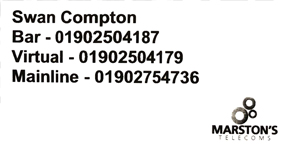
Check you have the correct site; Swan Compton below is just an example. -
I have the correct bag
-
Open the bag and take out the boxes - check the Marston's Telecoms stickers have the correct house name
-
Boxes have the correct stickers
-
How many VoIP handsets do you have?
- Handset 1
- Handset 2
- Handset 3
- Handset 4
- Handset 5
- Handset 6
- Handset 7
- Handset 7
-
Add each VoIP handset and enter Make - Model - Serial number
Example Cisco CP-7821 WZP21200QB9
VoIP Handset
-
Make - Model - Serial number
-
Additional notes if necessary
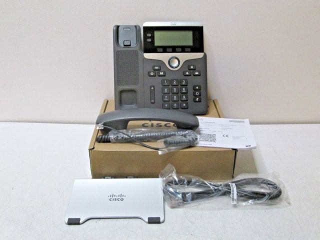
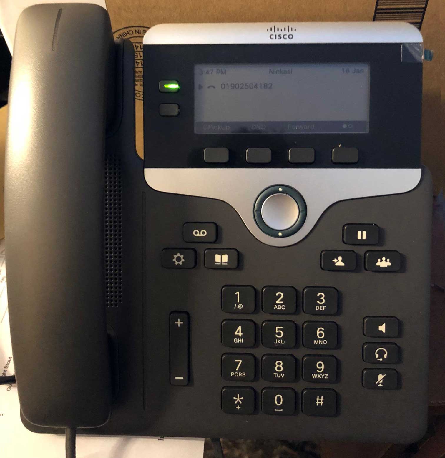
Installation of Cisco CP-7821
Installation Of Cisco CP-7821
-
In order to complete this install you will need the following items –
please check the status of the following before beginning: -
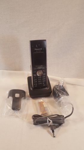
New Cisco CP-7821 Base Unit New Cisco CP-7821 Handset New Cisco CP-7821 Stand New Cisco CP-7821 Network cable
-
How many Cisco CP-7821 do you need to install?
-
Installation Checks - Add Cisco CP-7821 as necessary
Cisco CP-7821
-
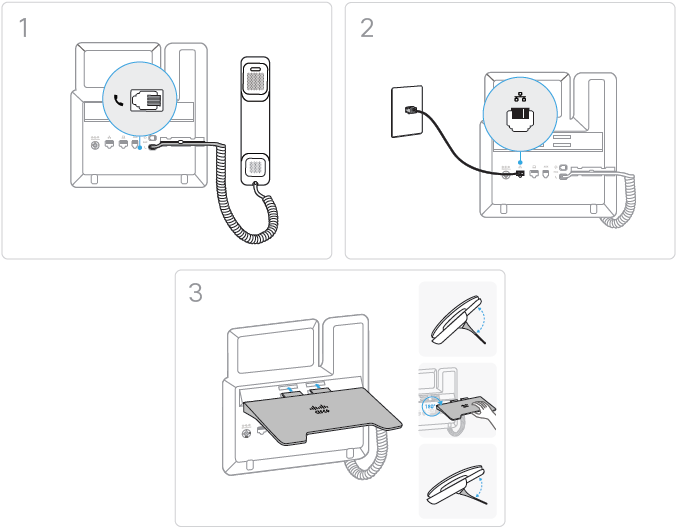
Installed the Cisco CP-7821 as below.
-
I have installed the Cisco CP-7821 as above.
-
What is the MAC address of the Cisco CP-7821 this can be found on the base Example; 70F35AD3BF82
-
Which port number did you connect the Cisco CP-7821 to? Example; Port 37
-
Take a picture of the handset location - This needs to show the work area.
-
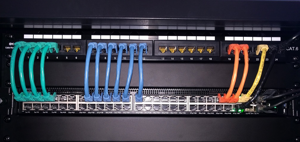
Ask the Manager to show you where the comms cabinet is located on site, the picture below shows the patch (TOP) and switch (BELOW)
-
The port number you made a note of before corresponds to the patch number, connect a network cable to that patch number.
-
Telecoms has requested that we use the correct ports on the Brocade and Cisco switches as below;
Port 20 is used for Cisco CP-7821 handset 1
Port 19 is used for Cisco CP-7821 handset 2
Port 18 is used for Cisco CP-7821 handset 3
If anything is connected in these ports then you must move them to a lower port number e.g. you can start from port 6 and upwards -
What port have to used on the switch?
-
Has the Switch Link LED light turn on and Activity light flashing?
-
Head back to the handset and wait for the flashing amber light to stop then the display should show the telephone number for that handset.
-
Amber light has stopped flashing and telephone number is being displayed.
-
Call your works number from the Cisco handset and then return the call to test incoming.
-
Telephone line is working.
-
Additional notes if necessary

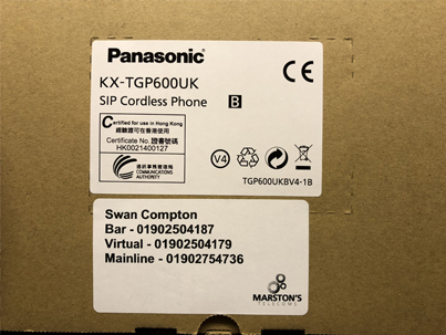
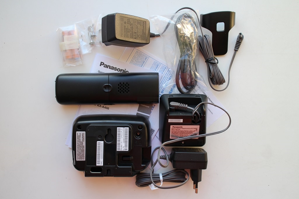
Installation of KX-TGP600
Installation Of KX-TGP600
-
In order to complete this install you will need the following items –
please check the status of the following before beginning: -
New KX-TGP600 - Antenna New KX-TGP600 - Ethernet Cable New KX-TGP600 - Antenna Charger New KX-TGP60 - Handset New KX-TGP60 - Handset Base New KX-TGP60 - Handset Base Charger New KX-TGP60 - Handset Batteries New KX-TGP60 - Handset Clip
-
How many KX-TGP600 do you need to install?
-
Installation Checks - Add KX-TGP600 as necessary
KX-TGP600
-
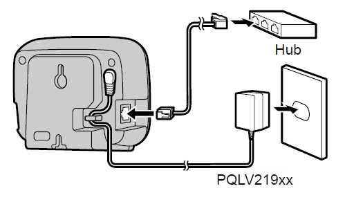
You will need to find a port which has the best location for signal coverage, using Ethernet cable connect the antenna to the port.
You shouldn't need to install the charger as the switch will have POE (Power Over Ethernet) -
I have installed the KX-TGP600 Antenna as above.
-
What is the MAC address of the KX-TGP600 Antenna which can be found on the base. Example; 70F35AD3BF82
-
Which port number did you connect the KX-TGP600 to? Example Port 37
-
Take a picture of the Antenna location - This needs to show the work area.
-
Ask the Manager to show you where the comms cabinet is located on site, the picture below shows the patch (TOP) and switch (BELOW)
-
The port number you made a note of before corresponds to the patch number, connect a network cable to that patch number.
-
Telecoms has requested that we use the correct ports on the Brocade and Cisco switches as below;
Port 21 is used for KX-TGP600 Antenna 1
Port 19 is used for KX-TGP600 Antenna 2
Port 18 is used for KX-TGP600 Antenna 3
If anything is connected in these ports then you must move them to a lower port number e.g. you can start from port 6 and upwards -
What port have to used on the switch?
-
Has the Switch Link LED light turn on and Activity light flashing?
-
Head back to the Antenna the status light should now be solid Red (Boot up 40 seconds) or flashing Amber (Obtaining IP Address)
-
Ask the Manager where he would like the handset installed but it will require a power socket.
Insert the batteries into the handset and attached the clip.
Connect the base charger and sit the handset into the cradle which will start charging.
Now turn the handset on (Hold down end call button) -
Handset is powered ON and charging
-
Take a picture of the Handset location - This needs to show the work area.
-
Take a picture of the Power socket being used by Handset - This needs to show the work area.
-
Once the Handset has paired itself to the base unit will start downloading an update which will take 10 minutes.
The handset will install and reboot. -
Handset has installed and rebooted
-
Call your works number from the handset and then return the call to test incoming.
-
Telephone line is working.
-
Additional notes if necessary

Installation Of KX-TPA60
Installation Of KX-TPA60
-
In order to complete this install you will need the following items –
please check the status of the following before beginning: -
New KX-TGP60 - Handset New KX-TGP60 - Handset Base New KX-TGP60 - Handset Base Charger New KX-TGP60 - Handset Batteries New KX-TGP60 - Handset Clip
-
How many KX-TPA60 do you need to install?
-
Installation Checks - Add KX-TPA60 as necessary
KX-TPA60
-
Ask the Manager where he would like the handset installed but it will require a power socket.
Insert the batteries into the handset and attached the clip.
Connect the base charger and sit the handset into the cradle which will start charging.
Now turn the handset on (Hold down end call button) -
Handset is powered ON and charging
-
Take a picture of the Handset location - This needs to show the work area.
-
Take a picture of the Power socket being used by Handset - This needs to show the work area.
-
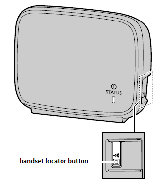
We need to pair the Handset to Antenna;
Press and hold the handset locator button for about 3 seconds.
The STATUS indicator on the base unit will flash red (slow flashing). -
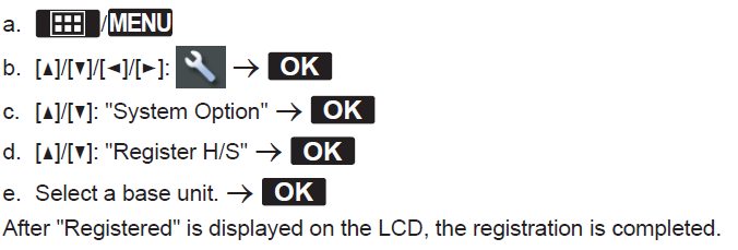
Follow the below instructions to register the handset to Antenna
-
Handset has connected to Antenna.
-
Once the Handset has paired itself to the base unit will start downloading an update which will take 10 minutes.
The handset will install and reboot. -
Handset has installed and rebooted
-
Call your works number from the handset and then return the call to test incoming.
-
Telephone line is working.
-
Till Checks - Add tills as necessary
Deinstall Old Handsets
Deinstall Old Handsets
-
How many old handsets are site keeping?
- 0 Handset's
- 1 Handset's
- 2 Handset's
- 3 Handset's
- 4 Handset's
- 5 Handset's
- 6 Handset's
- 7 Handset's
- 8 Handset's
-
Add each handset and enter Make - Model - Serial number
Old Handset
-
Make - Model - Serial number
-
How many old handsets are we removing?
- 0 Handset's
- 1 Handset's
- 2 Handset's
- 3 Handset's
- 4 Handset's
- 5 Handset's
- 6 Handset's
- 7 Handset's
- 8 Handset's
-
Add each handset and enter Make - Model - Serial number
Old Handset
-
Make - Model - Serial number
-
Additional notes if necessary
Comms Cabinet
Comms Cabinet
-
Open the Comms Cabinet and take a clear picture of everything inside. We need to see the Patch, Switch, Juniper, Cisco and DrayTek
-
Close the Comms Cabinet and take a clear picture of it's location - This needs to show the work area.
-
Additional notes if necessary
Engineers Sign Off
Engineers Sign Off
-
Call Marston’s Telecoms on 0808 280 0000 option 3 (9am till 5pm) for out of hours select option 2 and leave voice mail for Telecoms to call back.
You need to report your checks and any issues e.g.
• Can you make outgoing calls?
• Can the site receive incoming calls?
• Is the line clear of noise?
Telecoms may ask you to carry out more tests which you need to complete. -
Ask Telecoms for the Job number e.g. C12345
-
Who did you talk with at Marston's Telecoms
-
Call Project Control and confirm the job is completed
-
Who did you talk with from Project Control
-
Managers name
-
Managers signature
-
Engineers signature
-
Additional notes if necessary