Title Page
-
Site:
-
Technician:
-
Conducted on
-
Serial number
-
Charger version
-
Location
-
Customer
-
Vehicle
1. Photos of the Charger
-
Photo of charger
-
Photo inside of charger body
-
Photo inside of front of charger
-
Photo of cover
-
Photo of body
2. Wallbox Checks
-
2.1 Is the status LED on?<br>(Check electric installation and Molex, also if <br>there is any LED on inside)
-
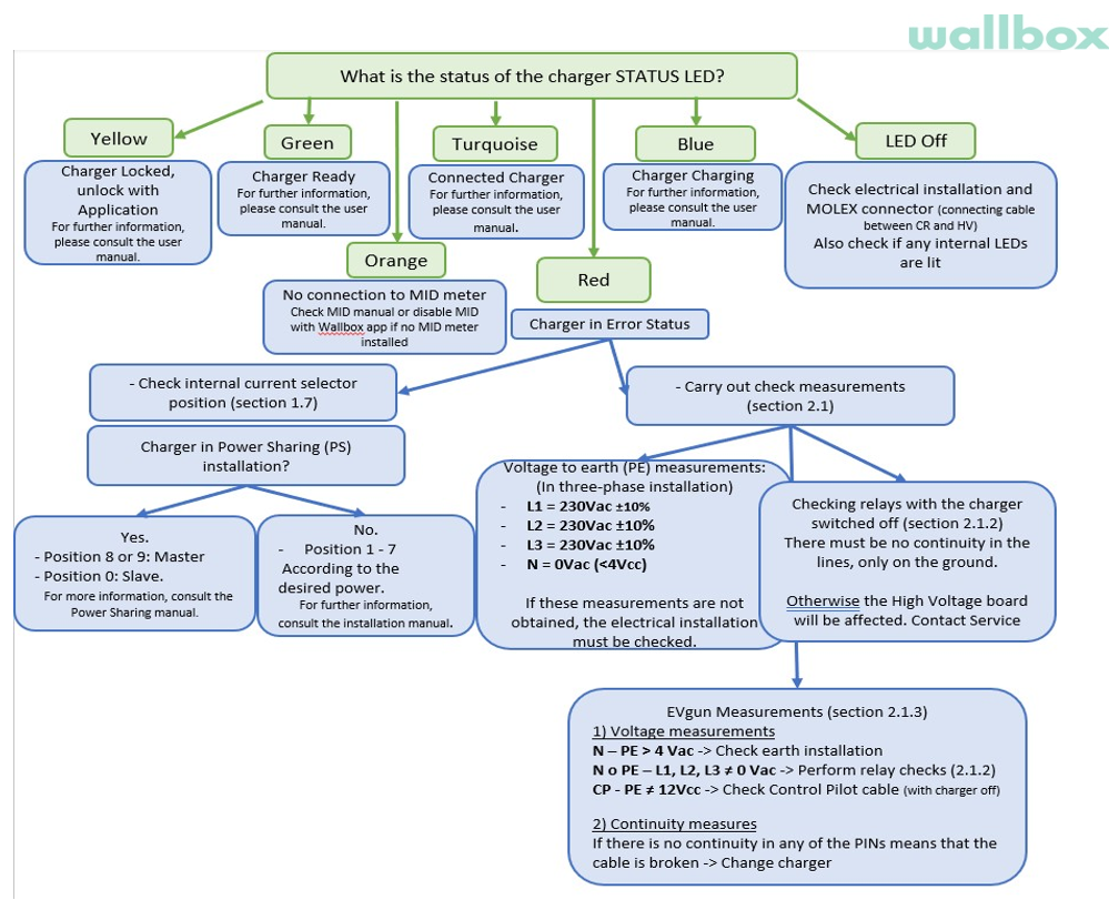
2.2 What is the color of the status LED? (review section 5.2. of the Annex)
- Yellow
- Green
- Blue
- Orange
- Red
- Turquoise
- LED off
- Blinking
-
2.3 Is possible to synchronize with Wallbox APP?
-
2.4 Charger appears on nearby devices? (check in the Bluetooth settings of the mobile (Android) or BLE Scanner 4.0 App (Apple))
-
2.5 Is it connected to internet?
-
2.6 Is the WallBox making any noise or buzzing?
-
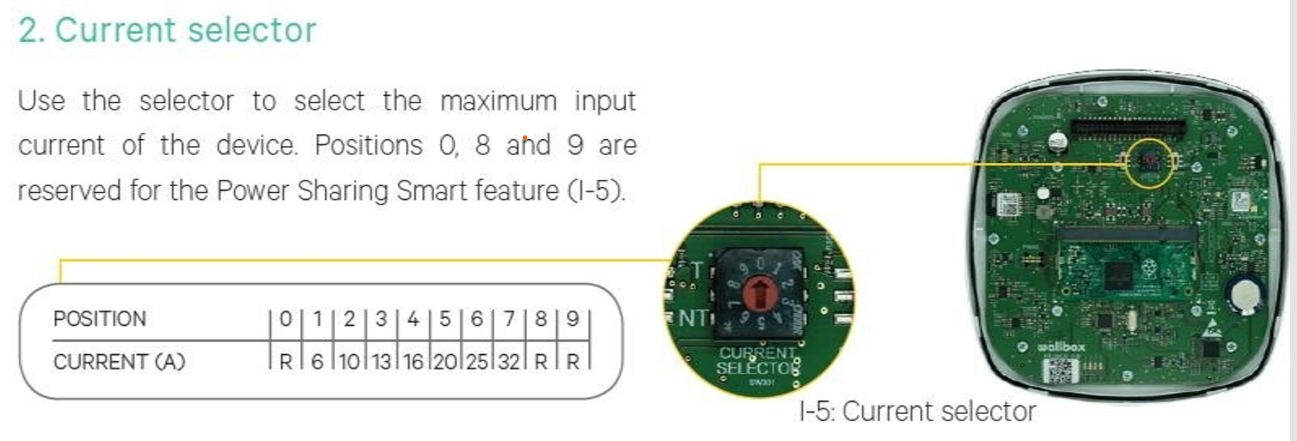
2.7 In what position is the current selector?
- 0
- 1
- 3
- 4
- 5
- 6
- 7
- 8
- 9
-
Current selector pic
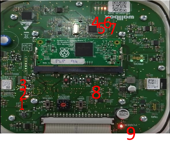
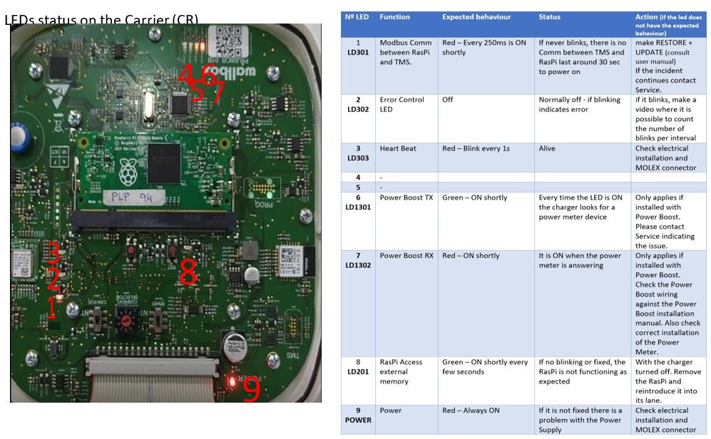
2.8 In which state are the LEDs on the Carrier(CR)
-
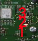
1 LD301 (Communication RPi-MCU) neðarlega vinstra megin ca milli tveggja skrúfa
-
-
2 LD302 (Normally off. If blinking, count the number of blinks and make a video) fyrir ofan nr. 1
-
3 LD303 (Hearbeat) fyrir ofan nr. 2
-
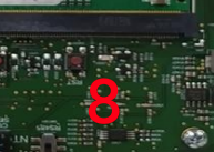
8 LD201 (RPI) fyrir neðan og hægra megin svarta langa stykkið í miðjunni, rétt neðan við hægri rofan fyrir TN stillingu
-
-
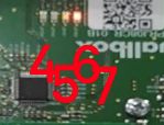
7 LD1302 (Power Meter feedback) fyrir neðan bo í Wallbox merkinu efst hægra megin(þar eru líka ljós 4,5 og 6 sem skipta ekki máli)
-
-
9 Power (POWER ON) neðst, vinstra megin við breiða kapalinn
-
-
Location of LED´s on the Carrier
2.9 In which position are the switches on the Carrier (CR)?
-
CAN BUS
-
RS485
3 Electric installation
-
Single-Phase
-
Bi-phase
-
Three-phase
-
IT
-
TT/TN
-
MCB(A)
-
RCD(Type)
-
Other:
3.1 Earth resistance of the charger instalation:
-
(Some EV car models do not accept more than 150 Ohm).
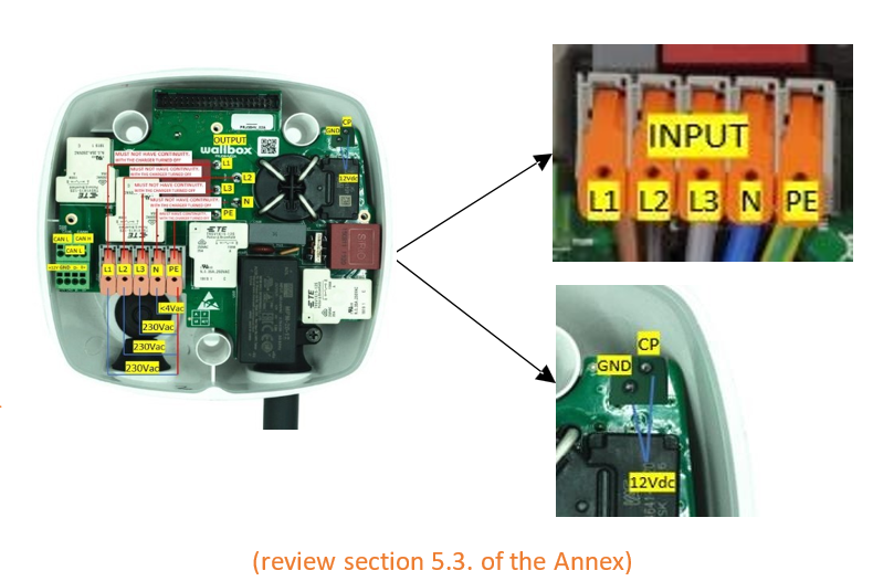
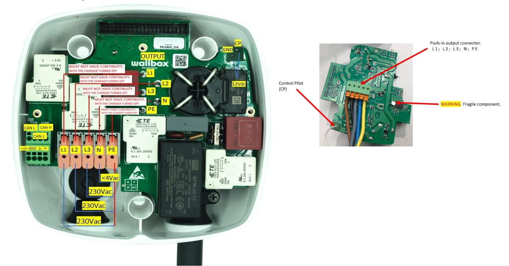
3.2 Voltage measurements on the charger: (review section 5.1. of the Annex)<br>The measurements in 3.2.1 and 3.2.2 must be carried out with power supply to the charger!
3.2.1 Measurements on the power supply of the charger.
-
N-PE (0Vac)
-
N-L1 (230Vac)
-
N-L2 (230Vac)
-
N-L3 (230Vac)
-
PE-L1 (230Vac)
-
PE-L2 (230 Vac)
-
PE-L3 (230Vac)
-
CP-PE (12Vdc)
-
Measurement power supply
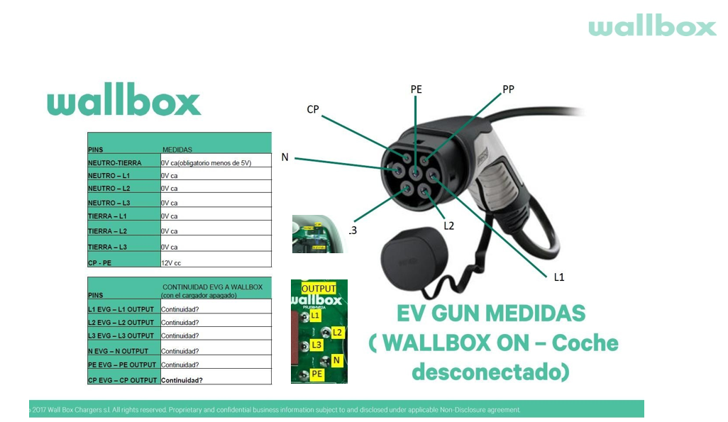
3.2.2 EVgun measures:
-
N-PE (0Vac)
-
N-L1 (0Vac)
-
N-L2 (0Vac)
-
N-L3 (0Vac)
-
PE-L1 (0Vac)
-
PE-L2 (0 Vac)
-
PE-L3 (0Vac)
-
CP-PE (12Vdc) (12 V in case no error is detected by the charger, as it would measure -12V)
-
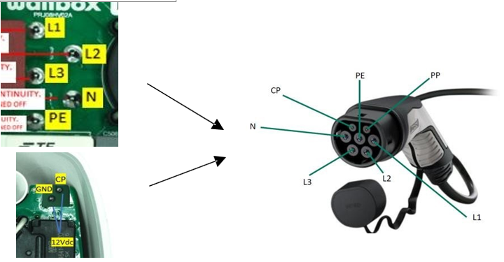
EV gun measures pic
3.3. Continuity measurements on the charger<br>The measurements in 3.3.1 and 3.3.2 and 3.3.3 must be carried out without power supply to the charger!
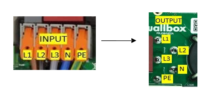
3.3.1 Verification of relays, must be measured between the supply connections and the terminals of the hose output: There must be no continuity in the lines, only on the ground (PE).
-
Continuity L1 input - L1
-
Continuity L2 input - L2
-
Continuity L3 input - L3
-
Continuity N input - N
-
Continuity PE input - PE output:
-
Continuity PE input - CP output:
-
Input output pic
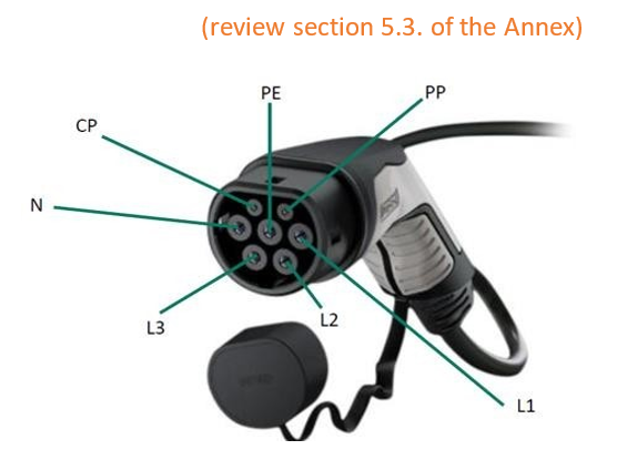
3.3.2 EVgun cable continuity: should be measured between the EVgun pins and the hose output terminals:
-
Continuity L1 EVg - L1 output:
-
Continuity L2 EVg - L2 output:
-
Continuity L3 EVg - L3 output:
-
Continuity N EVg - N output:
-
Continuity PE EVg - PE output:
-
Continuity CP EVg - CP output:
-
EV Gun pic and info on connections
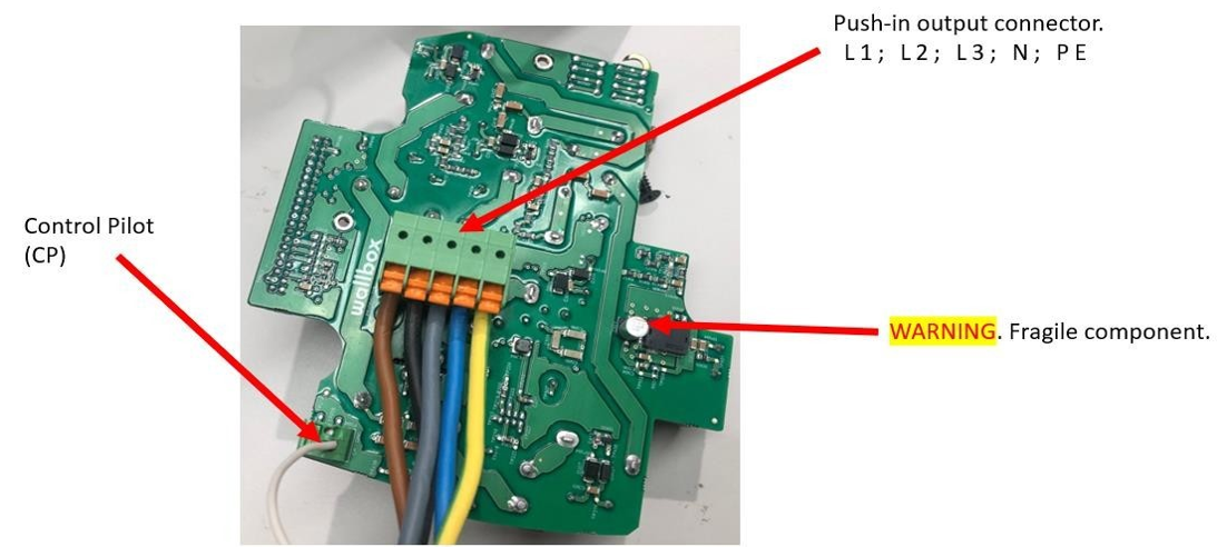
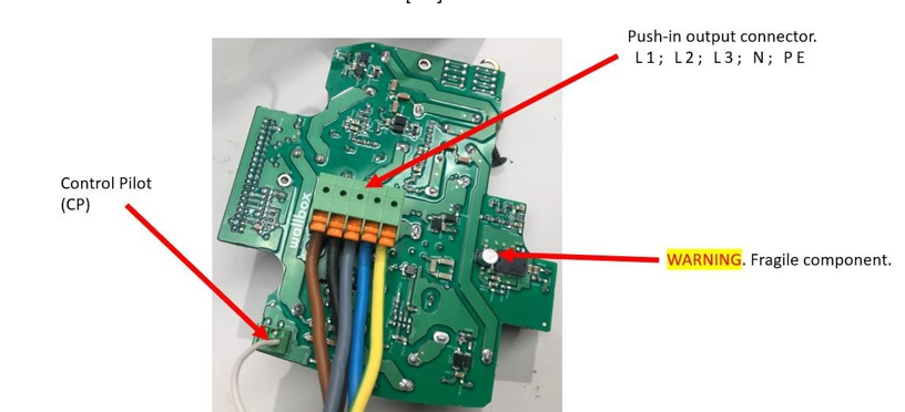
3.3.3 check output connections, rear HV-board Only in cases of no continuity of the Evgun or no 12Vcc in the CP or with or in cases of intermittent charges (review section 5.5. of the Annex)
-
Is the L1 properly connected?
-
Is the L2 properly connected?
-
Is the L3 properly connected?
-
Is the N properly connected?
-
Is the PE properly connected?
-
Is the CP properly connected?
-
Rear board pic
3.4. More details of the place of installation (eg, it is at the end of the line, there is heavy machinery nearby, it is located in an industrial area, ...)
-
Open answer
4. Resume
-
4.1. Spare part needed?
- Cover
- EV Gun
- Complete Unit
- PCB HV&PS
- PLAIN CABLE
- Plastics
-
4.2. Fault description:
5. Annex
-
5.1 PCB´s wiring
-
5.2 LED status
-
5.3 EV Gun measures:
-
5.4 LED status on the Carrier(CR)
-
5.5 Output connections, rear HV (Only in cases of no continuity on any of the measurements of the Evgun, point 3.3.2) check how to disassemble in the manual: "[EN] 20201001 Pulsar Plus Service Manual "
-
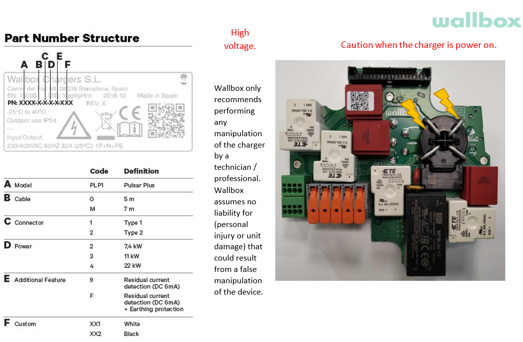
5.6 Product code


