


Title Page
-
Customer Name:
-
Customer postcode:
-
Conducted on
-
Prepared by
-
Location
Pre-Installation photos
-
Photo of electrical area pre-install (this is where you intend to put the sub board and add any miscallenous items such as henley blocks etc)
-
Photo of intended location of AIO+Gateway & inverter (See Job Pack as to where that is – and ensure customer is happy with this location)
-
Photo of the intended location of the Earthing Rod
-
Photo(s) of intended DC cable run (take multiple photos and annotate to show the run)
-
Photo(s) of intended AC cable run (take multiple photos and annotate to show the run)
-
Photo of AIO(s) SN:
-
Photo of Gateway SN:
-
Photo of grid meter(s) SN (main house meter):
-
Photo of Generation meter SN: (IF it is a DIN rail meter please take a photo of the front and photo of the Serial Number)
AIO/Gateway checklist
-
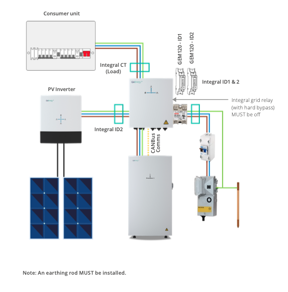
Layout of the system (An earthing rod MUST be installed):
-
Make sure ALL covers are off when commissioning. Apply covers when finished
-
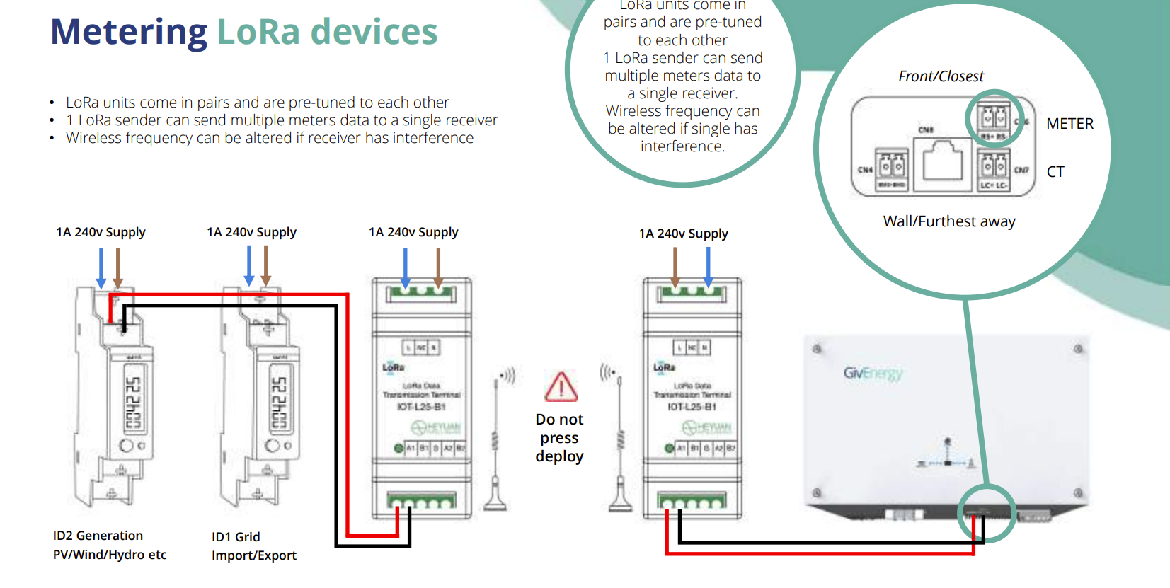
Does the system use LoRa device
-
Inverter side:
Gen 1
RS+ Positive goes to A1
RS- Negative goes to B1
Gen 2
Pin 6 - A1
Pin 7 - B1
Gen 3
Meter LC+ (the left port) goes to port A1
Meter LC- (the right port) goes to port B1
Grid meter side:
Pin 10 - A1
Pin 9 - B1 -
Are you stuggling to connect to the WIFI
-
When connecting the dongle the objective is to make the dongle solid blue(therefore make sure the cover is off). If you are struggling to connect the dongle when following the instructions :
1. Try doing the process on another device
2. Reset the dongle by pressing the black button near the DIP switches
3. Check the customer WIFI to make sure it is dual band and 2.4GHz
Post-installation pictures
-
Type of the Grid Inverter:
-
Take a photo and use Giv template
-
Take a photo and use Fox template
-
Take a photo of the inverter (showing clearance around it)
-
Take a photo of all the connections underneath the inverter.
-
Take a photo of the inverter's SN:
-
Take a photo of the inverter's Dongle/WiFi SN:
-
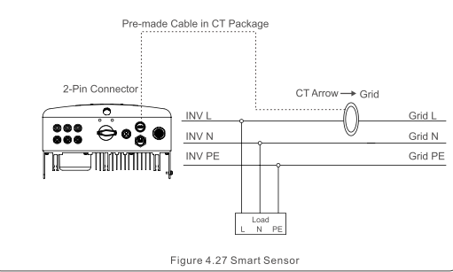
CT clamp of the inverter should be on the grid side
-
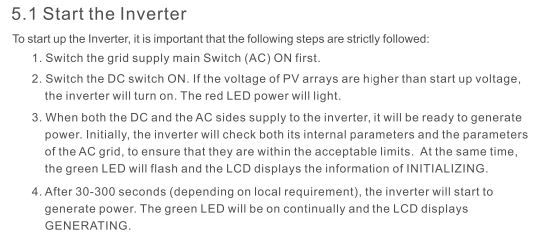
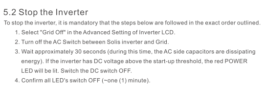
To start the inverter please follow the steps below:
-
Stop the inverter please follow the steps below:
-
Default password is "0010"
-
Menu operation:
-
Solis user manual (will download on your device)
-
Photo(s) of Inverter hazard stickers on Inverter.

DC Run
-
Photo of DC cable(s) entry into property – proving IP65 entry adequately waterproofed with silicon, CT1 or any other waterproof membrane/fire retardant
-
Photo of DC cable run (please take 1 photo for every room the cable has to run through) - WITH STICKERS
AIO
-
Take a photo of the AIO unit showing clearance around it (250mm on sides and 300mm on top)
-
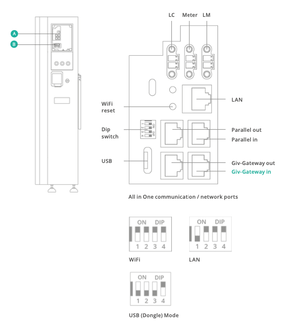
DIP switches
-
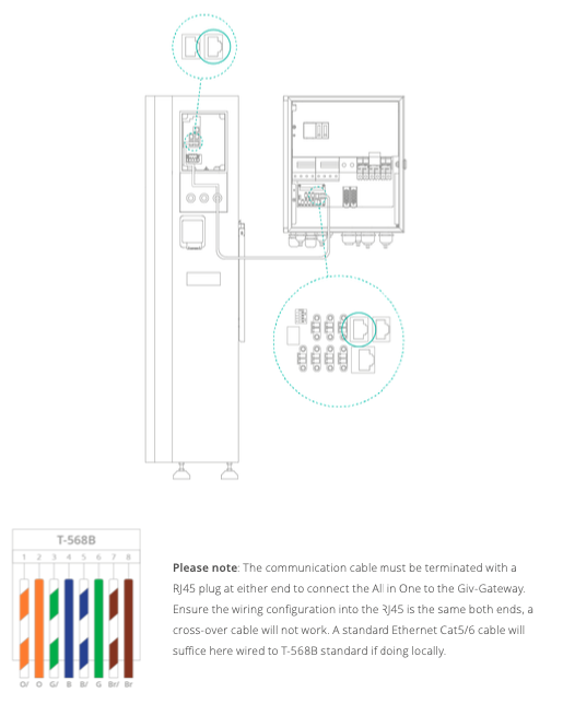
Communication cable of AIO and Gateway
-
Photo of communication cable of AIO and Gateway
-
Photo(s) of AIO connections WITHOUT cover on
-
Photo of AIO DIP switches
-
Photo(s) of AIO connections WITH cover on
-
Photo of AIO with lights showing its working
-
Photo(s) of Battery hazard stickers on AIO.
-
Is their more than 1 AIO?
Gateway
-
Photo of Gateway with cover off – (showing adequate clearances around them)
-
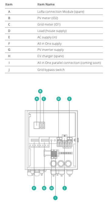
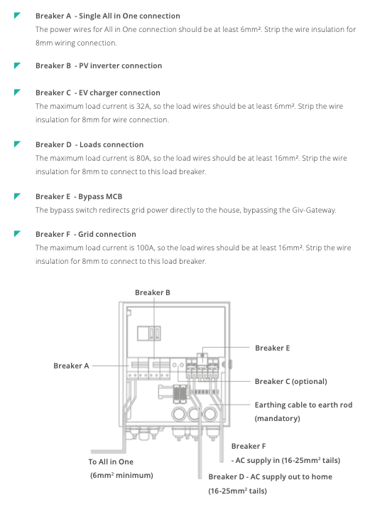
Gateway components:
-
MCB connections:
-
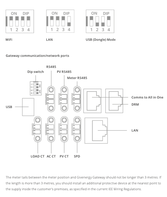
DIP switches and Gateway communication.
-
Photo of DIP Switches and network communications cable from the Gateway
-
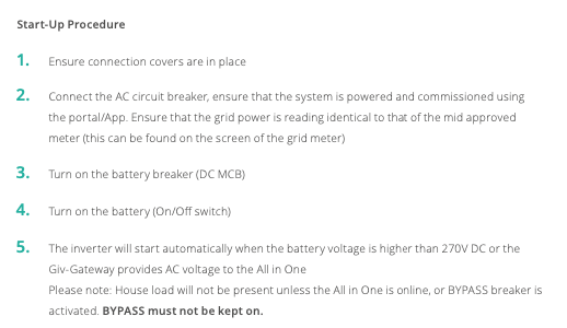
Start-up procedure:
-
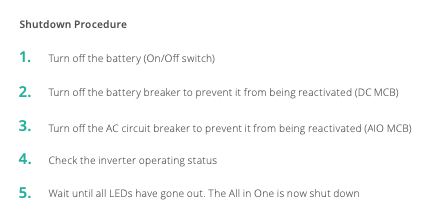
Shutdown procedure:
-
Photo of SN of the Gateway Meters
-
Photo(s) of Gateway connections WITHOUT cover on
-
Photo(s) of Gateway connections WITH cover on
-
Photo of Gateway with lights showing its working
-
Photo(s) of Inverter hazard stickers on Gateway
AC Run
-
Photo of AC cable entry into property – proving IP65 entry adequately waterproofed with silicon, CT1 or any other waterproof membrane
-
Photo of AC cable run (please take 1 photo for every room the cable has to run through)
Consumer unit & Mains electrical
-
Photo of Grid Inverter's CT clamp (for SOLIS arrow MUST point to the grid!)
-
Photo of the Earth rod connection.
-
Picture of inside the Meter box (to see the fuse head, meter, etc)
-
Are SLD and shutdown procedures available and placed near the DB?
-
Have you explained the Shutdown Procedure to the customer?
-
Take a photo of SLD and Shutdown Procedure near the DB.
-
Screenshot of system working
Test Results
-
Photo of total impedance for PV circuit – Zs (Ω)
-
Photo of external earth fault impedance - Ze (Ω)
-
Photo of prospective fault current – PFC (KA)
-
Photo of insulation resistance – (MΩ) - AC side
-
Photo for string 1 (V):
-
Photo for string 2 (V):
-
Test the AIO in island mode and provide photos of the readings between L+N, L+E, N+E.
Declarations
-
I confirm the install has been installed within accordance of BS7671 regulations
-
I confirm the inverter and battery are installed in a convenient location (as determined by the Customer), should allow easy access for future operations and maintenance personnel, and have sufficient space for cooling as defined by the manufacturer specifications.
-
Have you ensured all electrical items are secured and not loose?
-
Have you checked the Garage Unit / Sub-board for IP4x rating if installed inside? (If installed outside must be IP6x rated)
-
Can you confirm that you have recorded the MCB and RCD ratings?.
-
The RCD bus-bar link to MCB is correct (original bus bar or 25mm link) torque connections (1.7Nm)?
-
Confirm Henley block connections and ensure double insulated tails are correctly installed with no inner sheath showing torque connections (2.5Nm)?
-
Inspect AC isolator for IP4x rating, torque connections (1.7Nm)?
-
Check Generation meter/modem, trunking, IP4X, Torque connections(1.7Nm) and general installation condition on fireproof backing?
-
Visually make sure all connections do not have any copper showing at the terminals?
-
Checked all labels and applied all stickers?
-
Have you confirmed the Generation meter have been sealed ?
-
Have you pulled out the main fuse?
-
Have you confirmed the main fuse has been sealed
-
Is the app showing a load? - with the PV going direct to load or to the battery
-
Have you done a high load (kettle) test to check if the system is behaving correctly
-
Have you showed the customer the main isolation points of the system
-
Have you walked the customer through a reset procedure
-
Have you walked the customer on how the app works?
-
Has the site been cleaned, and waste removed?
-
Have all members of mounting structure been earthed? (if applicable)
-
Have all cables been laid in adequate conduit/ copex? (if applicable )
-
Have all wall / roof penetrations been adequately sealed?
-
Have inverters / battery been installed on fire-proof surface?
-
Have all safety distances near inverter and battery been respected?
-
Is any gas / water piping / equipment in the vicinity of the equipment?
-
Has the system been configured and its functioning state been verified?
-
Has it been verified whether installation area may be subject to water ingress / flooding?
-
Have all pre-existing and later damages in the installation area been recorded?
-
Has all equipment been installed according to the installation manuals and guidelines?
Signatures
-
I confirm this installation has been installed within MCS guidelines and the customer is happy and content with installation (including battery/inverter location, cable runs and sub-board placement)
-
Customer signature - confirming their are happy with installation
