


Title Page
-
Customer Name:
-
Customer postcode:
-
Conducted on
-
Prepared by
-
Location
Pre-Installation photos
-
Photo of electrical pre-install area (this is where you intend to put the sub board and add any miscellaneous items such as henley blocks etc)
-
Photo of intended location of battery & inverter (See Job Pack as to where that is – and ensure customer is happy with this location)
-
Photo(s) of intended DC cable run (take multiple photos and annotate to show the run)
-
Photo(s) of intended AC cable run (take multiple photos and annotate to show the run)
-
Photo of Inverter/Dongle/WIFI plate SN:
-
Type of Battery
-
Photo of Battery(s) SN:
-
Photo of grid meter(s) SN:
-
Photo of Generation meter SN:
-
Is the number of panels greater than 12?
-
If number of panels are greater than 12 please LIMIT the inverter to 3.68 upon commissioning
Inverter checklist
-
Make sure ALL covers are off when commissioning. Apply covers when finished
-
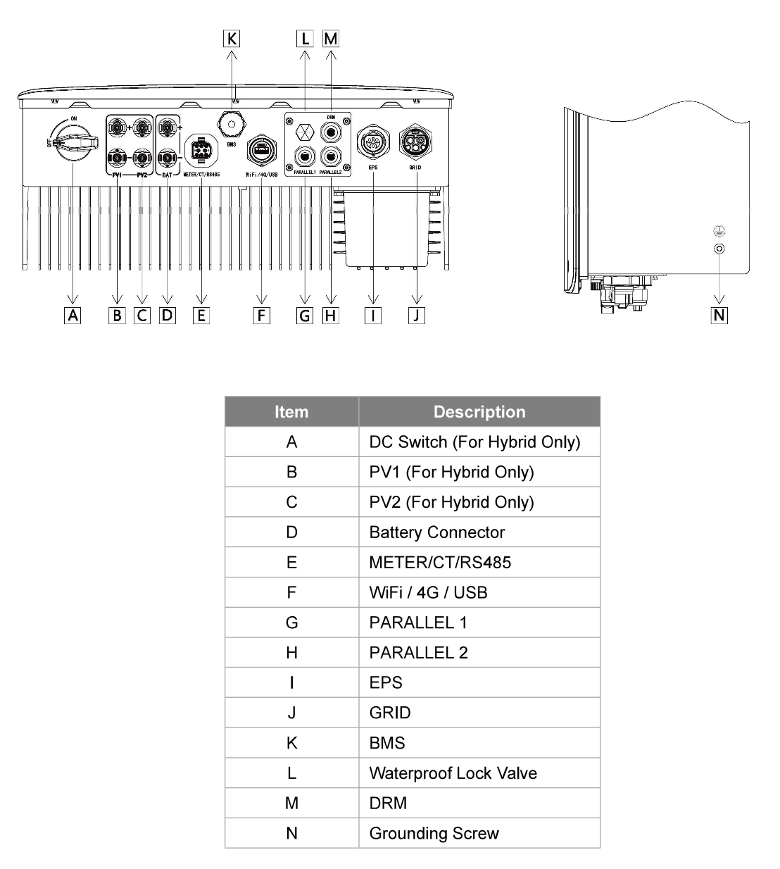
Terminals of the Fox inverter
-
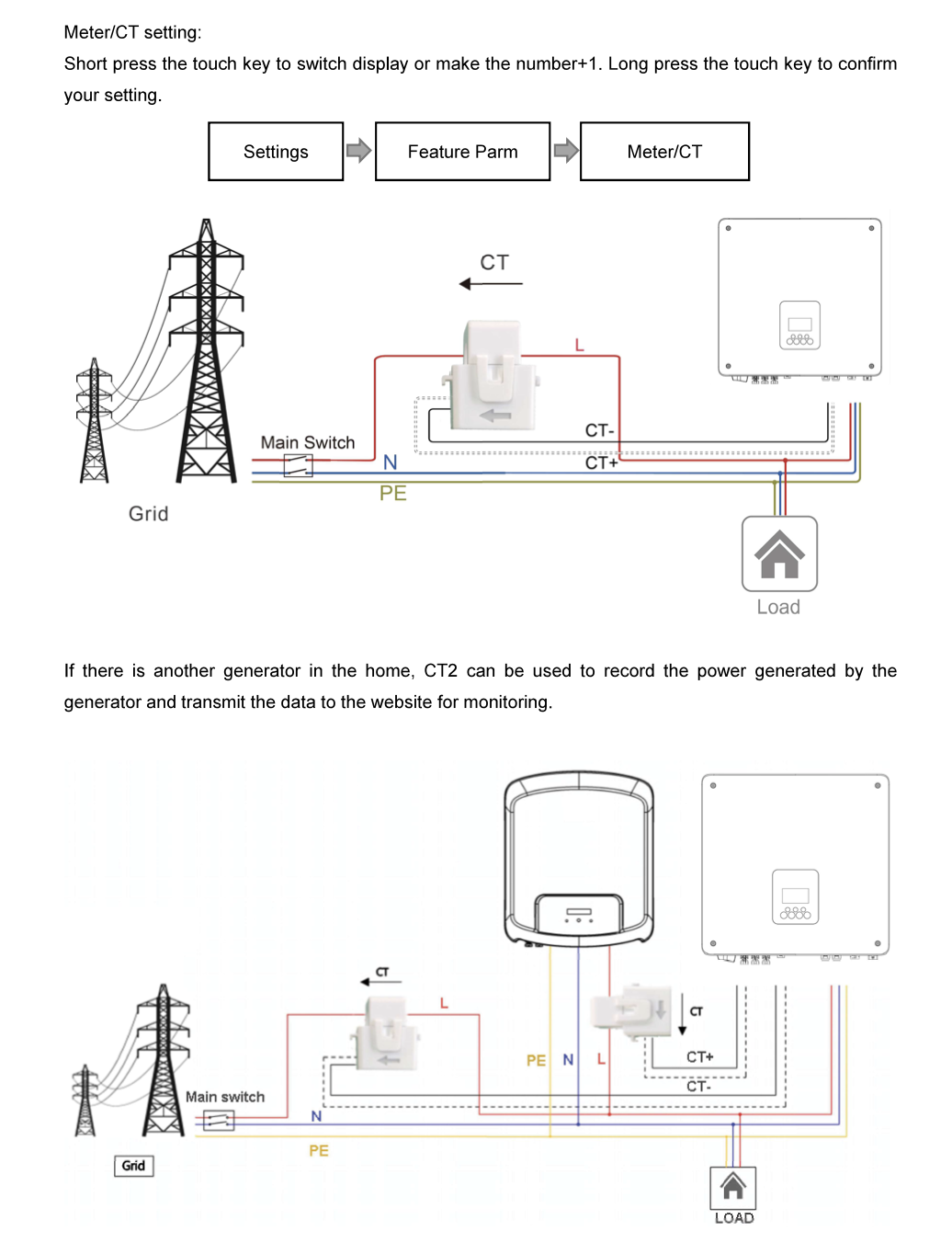
CT setting and orientation
-
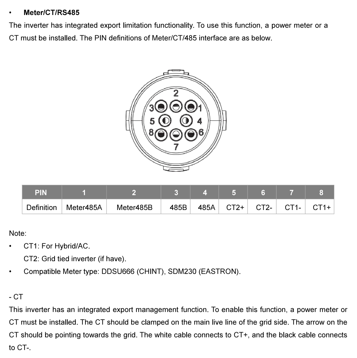
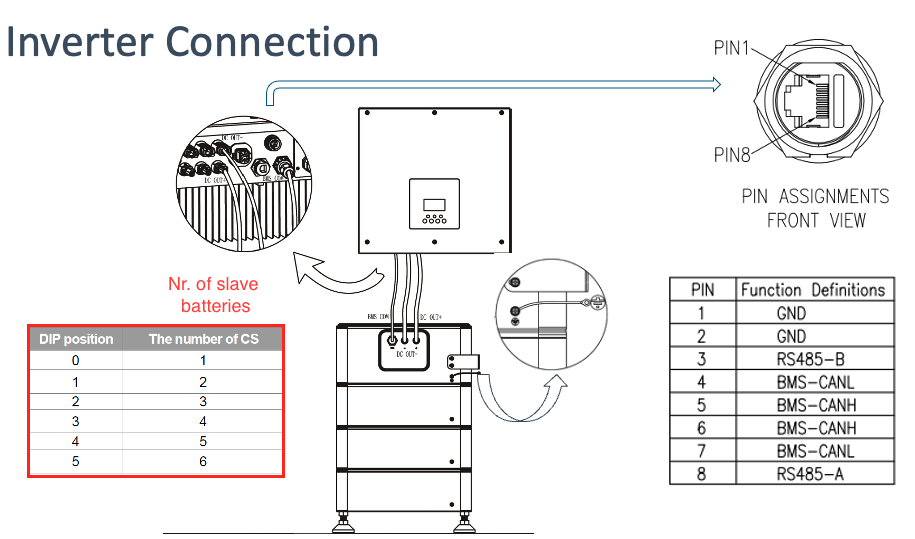
PIN Connections for H1 Fox inverter
-
Battery control
-
so scriu mai sus
-
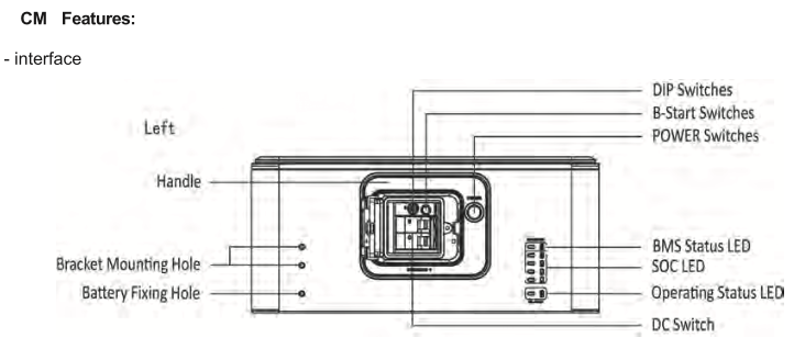
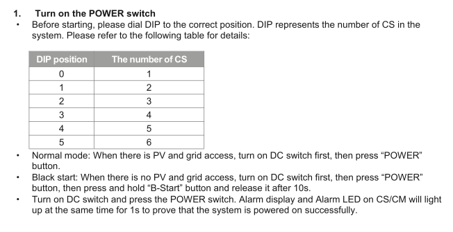
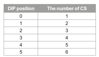
Inverter Connection (DIP switch on Master battery (CM)), (CS = slave)
-
Turn-ON the battery
-
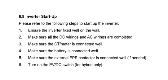
Inverter Sart-UP:
-
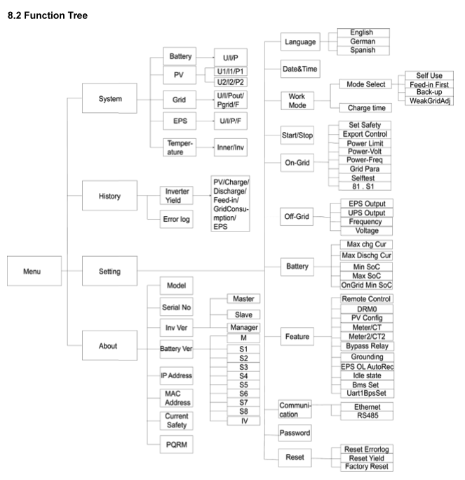
Menu Function Tree
Post-installation pictures
DC Run
-
Photo of DC cable(s) entry into property – proving IP65 entry adequately waterproofed with silicon, CT1 or any other waterproof membrane/fire retardant
-
Photo of DC cable run (please take 1 photo for every room the cable has to run through) - WITH STICKERS
Battery and Inverter
-
Photo of battery and inverter – (showing adequate clearances around them and isolators/generation meter)
-
Battery and inverter Bonding
Nr of Battery stacks
-
H2
-
H3
-
H4
-
H5
-
H6
-
H7
-
Move DIP switch to its position
-
Photo of the Battery's DIP switch
-
Photo of Battery and Inverter data connection
-
Photo of the inverter's LCD on showing its working
-
Photo(s) of all Inverter's connections
-
Photo(s) of hazard stickers on Inverter and battery
AC Run
-
Photo of AC cable entry into property – proving IP65 entry adequately waterproofed with silicon, CT1 or any other waterproof membrane
-
Photo of AC cable run (please take 1 photo for every room the cable has to run through)
Consumer unit & Mains electrical
-
Photo of handover documents (inc SLD and shutdown procedure) placed near the inverter
-
Photo(s) of consumer unit with cover OFF (showing connections of the PV breaker, RCD, SPD and grid meter)
-
Photo(s) of consumer unit with cover ON (showing the PV breaker, RCD, SPD and grid meter)
-
Photo of CT clamp around LIVE outgoing meter tail – with arrow pointing towards GRID
-
Picture of overall electrical install showing sub-board, CT clamp, Henley/Lucy blocks and main earthing terminal (COVERS ON)
-
Screenshot of system working
Test Results
-
Photo of total impedance for PV circuit – Zs (Ω)
-
Photo of external earth fault impedance - Ze (Ω)
-
Photo of prospective fault current – PFC (KA)
-
Photo of insulation resistance – (MΩ) - AC side
-
Photo for string 1 (V):
-
Photo for string 2 (V):
Declarations
-
I confirm the install has been installed within accordance of BS7671 regulations
-
I confirm the inverter and battery are installed in a convenient location (as determined by the Customer), should allow easy access for future operations and maintenance personnel, and have sufficient space for cooling as defined by the manufacturer specifications.
-
Have you ensured all electrical items are secured and not loose?
-
Have you checked the Garage Unit / Sub-board for IP4x rating if installed inside? (If installed outside must be IP6x rated)
-
Can you confirm that you have recorded the MCB and RCD ratings?.
-
The RCD bus-bar link to MCB is correct (original bus bar or 25mm link) torque connections (1.7Nm)?
-
Confirm Henley block connections and ensure double insulated tails are correctly installed with no inner sheath showing torque connections (2.5Nm)?
-
Inspect AC isolator for IP4x rating, torque connections (1.7Nm)?
-
Check Generation meter/modem, trunking, IP4X, Torque connections(1.7Nm) and general installation condition on fireproof backing?
-
Visually make sure all connections do not have any copper showing at the terminals?
-
Checked all labels and applied all stickers?
-
Have you confirmed the Generation meter have been sealed ?
-
Have you pulled out the main fuse?
-
Have you confirmed the main fuse has been sealed
-
Is the app showing a load? - with the PV going direct to load or to the battery
-
Have you done a high load (kettle) test to check if the system is behaving correctly
-
Have you showed the customer the main isolation points of the system
-
Have you walked the customer through a reset procedure
-
Have you walked the customer on how the app works?
-
Has the site been cleaned, and waste removed?
-
Have all members of mounting structure been earthed? (if applicable)
-
Have all cables been laid in adequate conduit/ copex? (if applicable )
-
Have all wall / roof penetrations been adequately sealed?
-
Have inverters / battery been installed on fire-proof surface?
-
Have all safety distances near inverter and battery been respected?
-
Is any gas / water piping / equipment in the vicinity of the equipment?
-
Has the system been configured and its functioning state been verified?
-
Has it been verified whether installation area may be subject to water ingress / flooding?
-
Have all pre-existing and later damages in the installation area been recorded?
-
Has all equipment been installed according to the installation manuals and guidelines?
Signatures
-
I confirm this installation has been installed within MCS guidelines and the customer is happy and content with installation (including battery/inverter location, cable runs and sub-board placement)
-
Customer signature - confirming their are happy with installation
