


Information
-
Document No.
-
Audit Title
-
Client / Site
-
Conducted on
-
Prepared by
-
Location
-
Personnel
BARRIER INFORMATION
-
ENTER AVB TYPE
-
Model
-
Serial Number
(TAKE PICTURES)
-
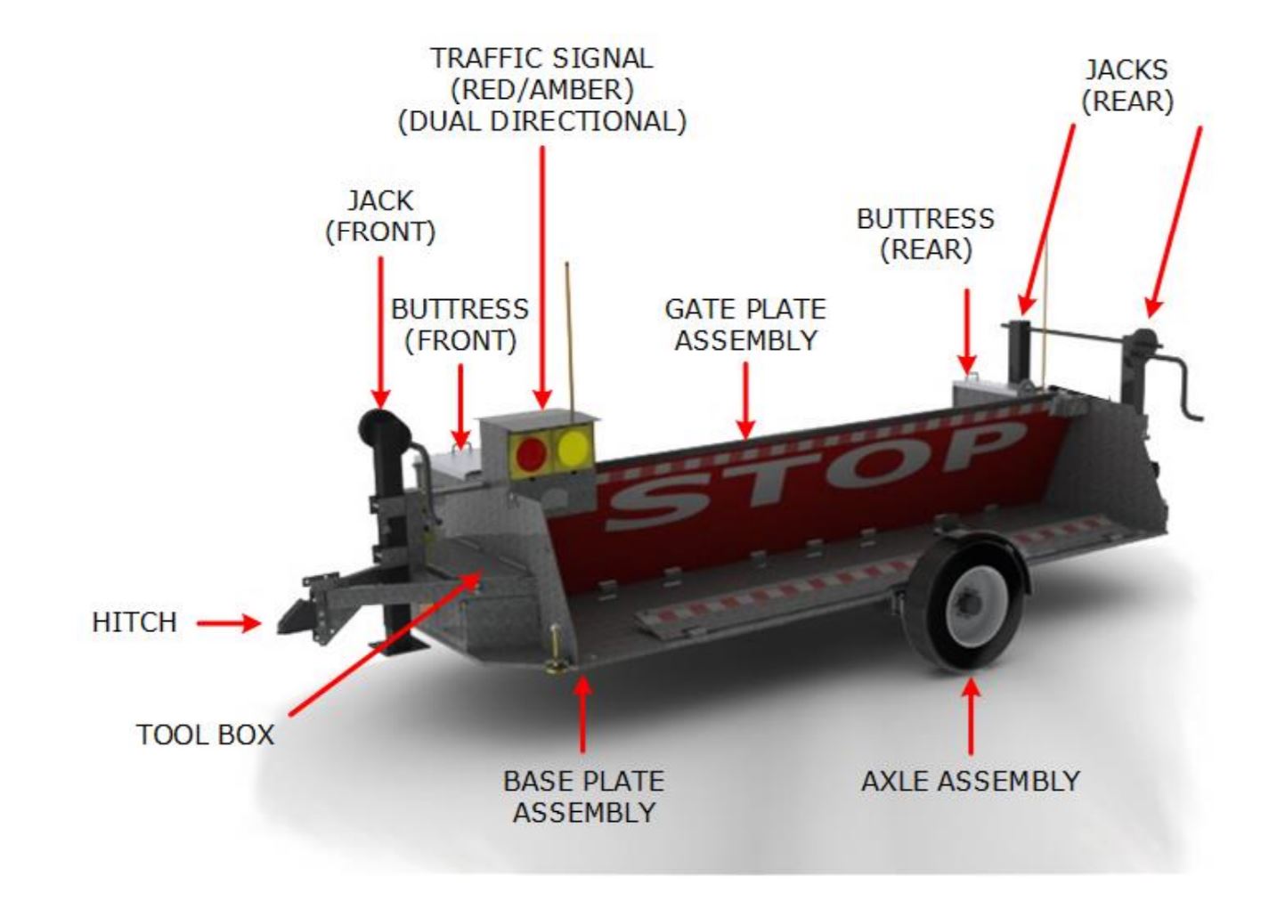
BARRIER DIAGRAM
FRONT TONGUE AREA
-
1. Tongue and Assembly
-
2. Pintle Hitch-Nuts, Bolts, Washers
-
3. 24-12 Volt Converter box
-
4. Breakaway Switch and Assembly
-
5. Front Marker Lights and Assembly (2)
-
7. Remote SDI Connector
-
8. AC Power Box Control Connector & Labels
-
9. Jacks & Welds, Handle, Assembly-Crank
-
10. Battery Charger (Housing Area)
-
11. Tether controller operation
-
12. Battery
FRONT HOUSING
-
13. Hydraulic Power Unit & Mounting
-
14. Hydraulic Cylinder, Mounting & Hoses
-
15. Spring & Assembly
-
16. Control Box and Panel
-
17. Lid & Mounting
-
18. Decals on top of lid
-
19. Schematic attached to door handle
-
20. Limit Switches (2) and Mounting
-
21. Battery Box and Mounting (ground to Barrier)
-
22. Traffic Lights, Function and Seal
-
23. Door and Lid Secured
REAR HOUSING
-
24. Spring & Assembly (nut)
-
25. NOT USED
- Yes
- No
- N/A
-
26. Lid and Mounting and Lid Decal
-
27. Gate Lock
VISUAL OUTSIDE RIGHT
-
28. Tire Condition
-
29. Rim/Lug Nuts/Axle Hub Oil Plastic Cap
-
30. Marker Lights
-
31. Axles and Assembly
-
32. Break Drum and Assembly
-
33. Fenders-Decal, Align, Apprrearance
-
34. Electrical and Brake Connection
-
35. Gate Door
TOOL BOX CONTENTS
-
36. Safety Chains
-
37. Master Control Box with SDI Connector
- Yes
- No
- N/A
-
38. Pliers
- Yes
- No
- N/A
-
39. Adjustable Wrench
- Yes
- No
- N/A
-
40. Push Button Control w/cord
- Yes
- No
- N/A
-
41. Lug Wrench
- Yes
- No
- N/A
-
42. Break Controller
- Yes
- No
- N/A
-
43. Axel Pins (4)
- Yes
- No
- N/A
-
44. Manual Lift Bars
- Yes
- No
- N/A
-
45. CD/OM Manual
- Yes
- No
- N/A
WELDING
-
46. Visual Inspection of Structural Welds
-
47. NOT USED
VISUAL OUTSIDE LEFT
-
48. Tire Condition
-
49. Rim/Lug Nuts/Axle Hub Oil Plastic Cap
-
50. Marker Light
-
51. Axle and Assembly
-
52. Break Drum and Assembly
-
53. Fenders-Decal, Align, Appearance
-
54. Electrical and Brake Connection / Wire tied up
-
55. Decals on Gate
REAR BUMPER AREA
-
56. Marker Lights
-
57. Turn Signals/Break Lights
-
58. Jacks & Welds/Connecting Bar-Crank
-
59. Bumper & Assembly
-
60. Tag Bracket
-
61. Barrel Plugs in Place (3)
-
62. Lifting Lugs (2)
-
63. VIN Sticker applied
BARRIER TEST - OPERATION/CYCLE BARRIER SECURE (UP)/ UNSECURE (DOWN)
-
64. Cycle Barrier (Min 5 Cycles UP/DOWN)
-
65. Verify Traffic Signal - Barrier Un-secured/Down - Light is Yellow
-
65. Verify Traffic Signal - Barrier Secured/UP Light is RED
Hand Pump Operation - Manual Operation (refer to section 4.5.2.2 for procedure)
-
66. Barrier in The Un-Secured/Down Position - Using Hand Pump Raise Barrier to Secure Position
Jack Operation - Manual and Drill
-
67. Raise and Lower Jacks by Manual Operation
-
68. Raise and Lower Jacks with with Cordless Drill
COMMENTS AND RECOMMENDATIONS
-
Comment/Recommendation
AUTHORIZED BY AND INSPECTED BY
-
End User:
-
Authorized By:
-
Nasatka Rep:


 - Factory Acceptance Testing (FAT)")

