Information
-
Document No.
-
Audit Title
-
Client / Site
-
Conducted on
-
Prepared by
-
Location
-
Personnel
Cabinet Inspection
-
Visually check the rack for any damage or scratches caused during the build process.
Minor scratches should be repaired using the colour coded touch up paint. -
Front of rack?
-
Left side of rack?
-
Right side of rack?
-
Back of rack?<br>
-
Inside rack?<br>
Cabinet Kit List.
-
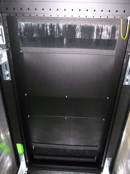
Brush Strips should be installed as per image.
-
Does the rack have correctly installed brush strips?<br>
-
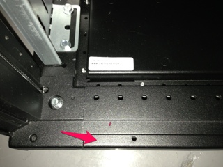
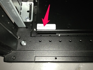
The Rack Build reference is located here:
-
Enter the Build reference i.e. Rack build Spec A
-
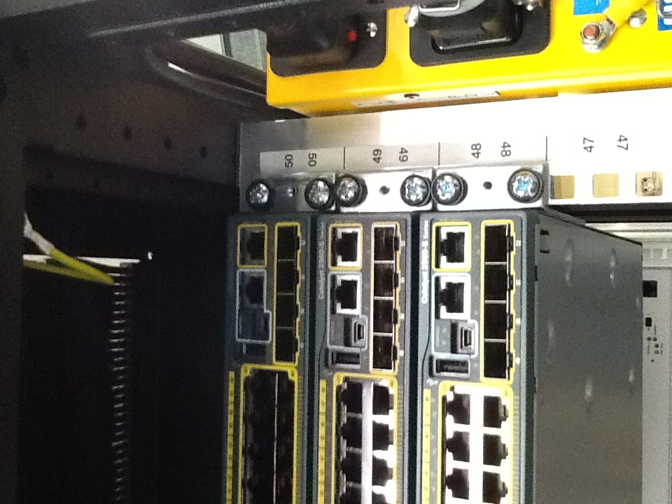
The switches should be installed in the following order and U positions as shown:
-
Are the switches installed in the correct U location according to the specific build requirement?
Power Configuration.
-
There are two types of rack build, "A" with yellow PDU at the top and "B" with the green PDU at the top. The image depicts Rack Build "A"
-
Which type of rack build A or B?<br>
-
For rack build A (mark n/a for build B)
-
Source 1 Baytech installed?<br>
-
Confirm Yellow PDU above Green PDU?
-
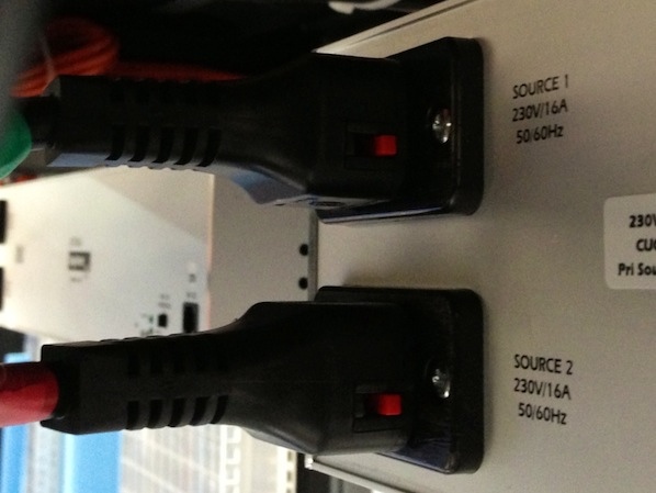
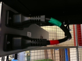
PC1285 power cords should be locked in position as per the picture:
-
Confirm each of the Baytech PC1285 power cords are locked in place
-
The picture depicts Rack Build A taping:
-
Confirm power cord are all labelled with tape as per the image.<br>
-
For rack build B (mark n/a for build A)
-
Source 2 Baytech unit installed?
-
Confirm Green PDU above Yellow PDU?<br>
-
PC1285 power cords should be locked in position as per the picture:
-
Confirm each of the Baytech PC1285 power cords are locked in place?<br>
-
The picture depicts Rack Build B taping:
-
Confirm power cords are all labeled with tape?
-
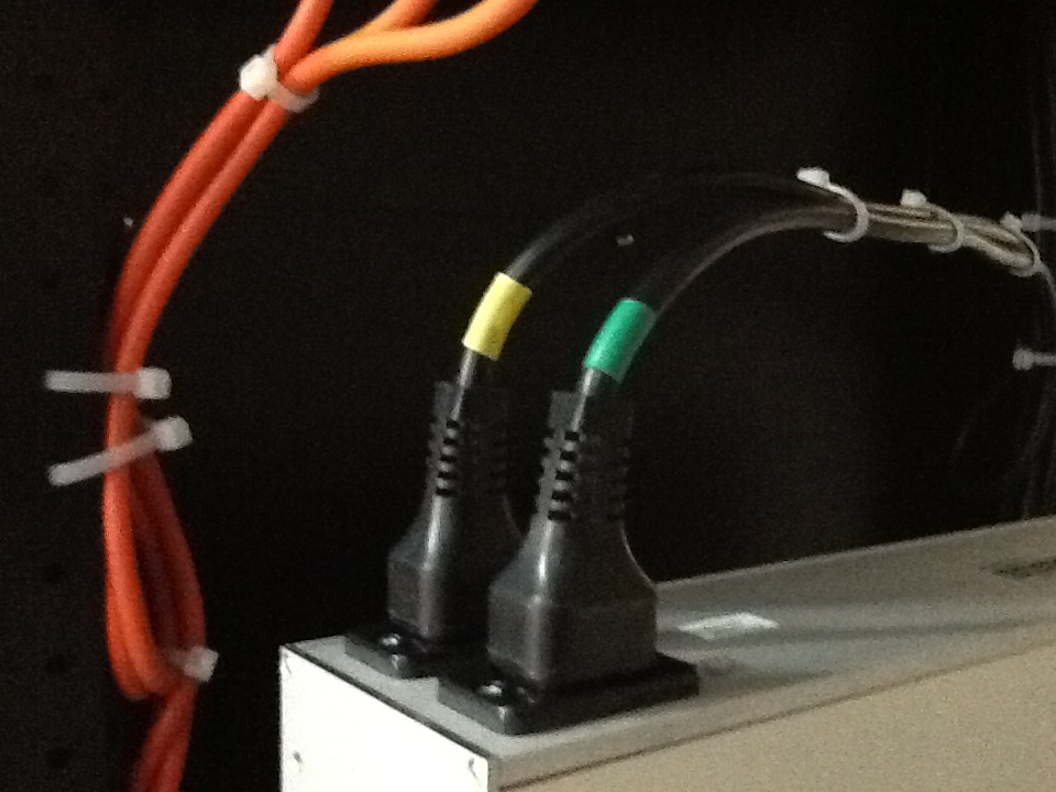
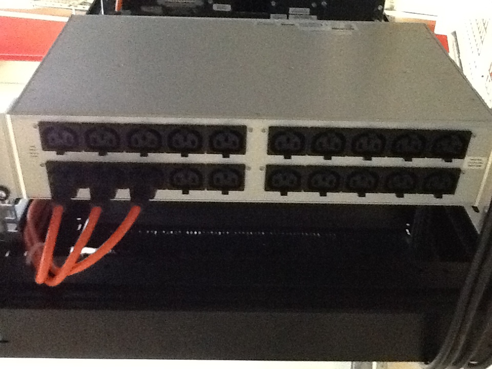
The orange leads should be plugged into the Baytech unit as shown:
-
Are the orange PC938 power cords plugged into correct position?<br>
-
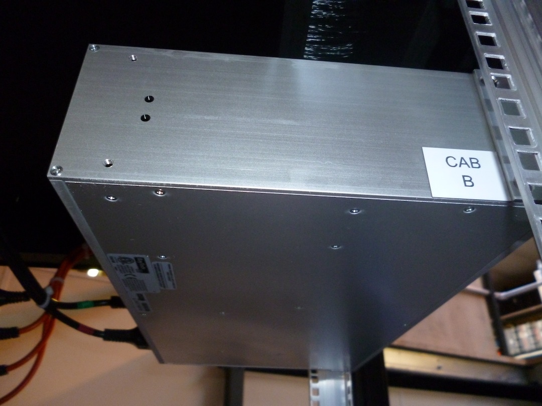
Location of Baytech ID label for Rack Build "A" and "B"
-
Confirm correct placement of Baytech ID label?
PDU's
-
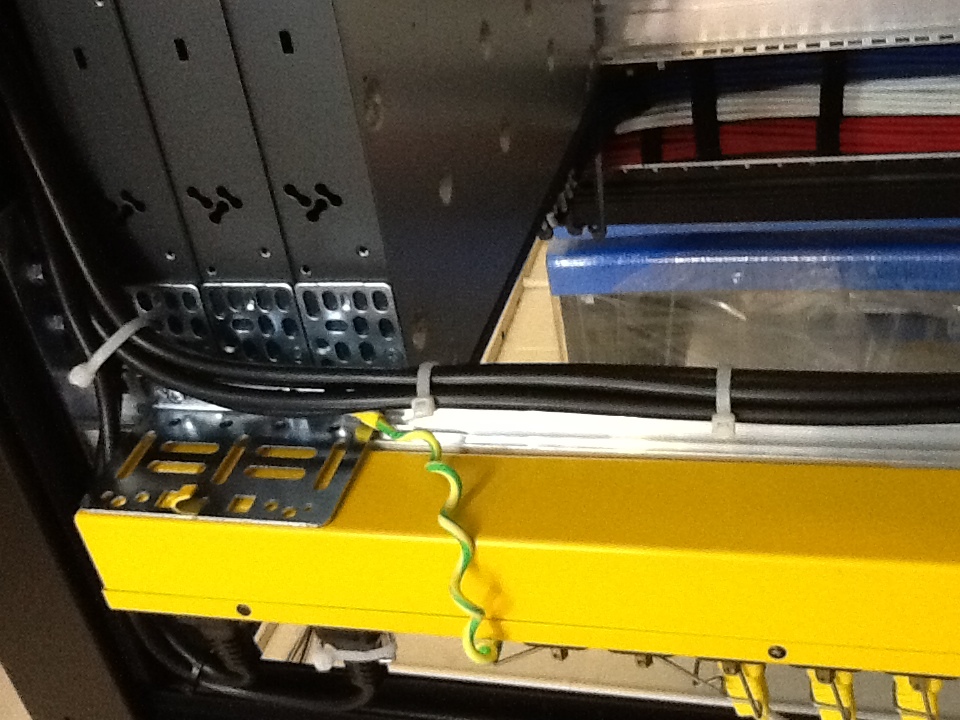
Yellow and green PDU's should be earthed as shown:
-
Confirm that all PDU's are correctly earthed.<br>
-
Labelling example shown:
-
Check PDU's are labelled:<br><br>1st (top) "PDU 1"<br>2nd. "PDU 2"<br>3rd. "PDU 3"<br>4th. "PDU 4"<br><br>
-
PDU 1 labelling 10A - 17A<br>
-
PDU 2 labelling 10B - 17B?
-
PDU 3 labelling 1A - 9A?
-
PDU 4 labelling 1B - 9B?
Power Cords
-
Are C19 cords locking in position and correctly seated?
-
Check and trace commando end 1YLW PDU - confirm correct label "1YWL PDU"?
-
Check and trace commando end 2YLW PDU - confirm correct label "2YLW PDU"?
-
Check and trace commando end 1GRN PDU - confirm correct label "1GRN PDU"?
-
Check and trace commando end 2GRN PDU - confirm correct label "2GRN PDU"?
-
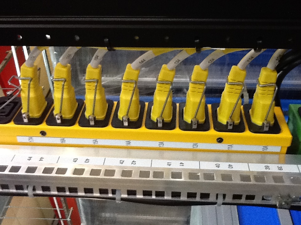
Are PC1285 power cords clipped and cable tied?
-
Confirm 34 no. Power cords secured with locking clips and correctly seated?
-
Confirm PDU 1 labelling (starting from top) 17A -10A and ensure labels are clearly visible?
-
Confirm PDU 2 labelling (starting from top) 17B -10B and ensure labels are clearly visible?
-
Confirm PDU 3 labelling (starting from top) 9A -1A and ensure labels are clearly visible?
-
Confirm PDU 4 labelling (starting from top) 9B -1B and ensure labels are clearly visible
-
Confirm cable ties are all cut flush?
-
Are male commando cables consistently routed?
-
Confirm PC938 power cords are consistently routed?
-
Confirm power cord in position U26 is routed under the middle bar not over?
Switches
Data Cords and Fitting.
-
The photo shows the correct mounting positions for the switches.
-
Confirm Switches are mounted as per photo?<br>
-
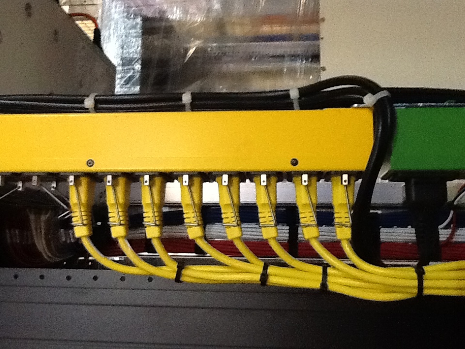
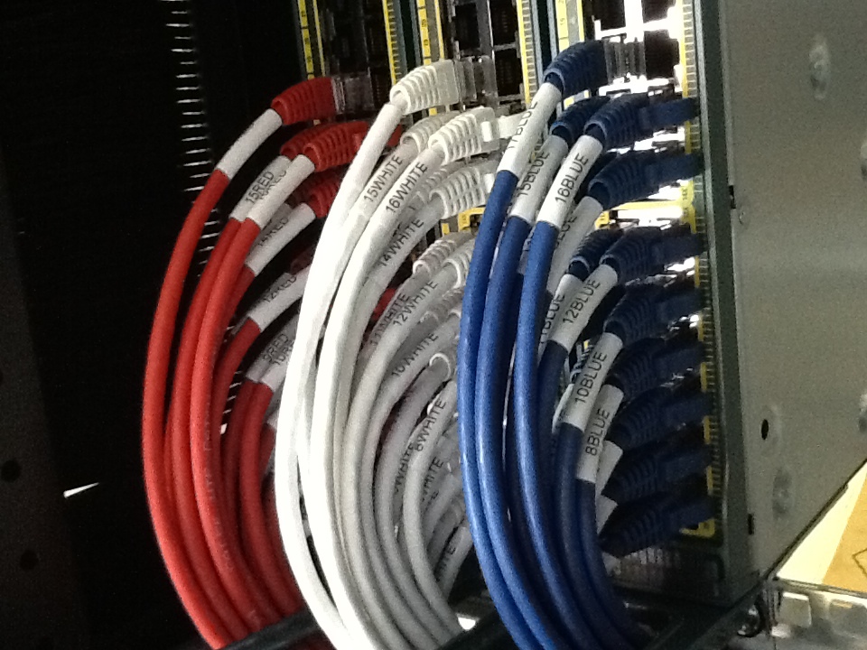
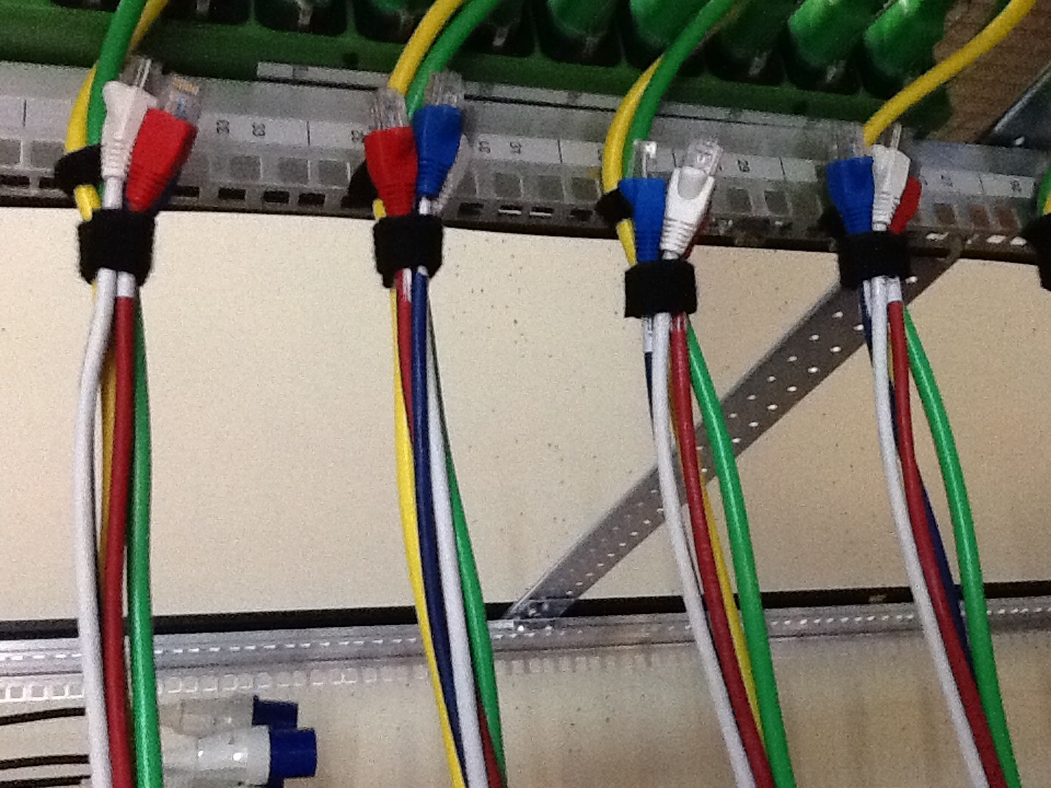
The photo shows correct switch patching:
-
Confirm Switch 1 is patched with RED leads?<br>
-
Confirm Switch 1 leads labelled as 1-17RED and are in correct corresponding port no. ?
-
Confirm Switch 2 is patched with WHITE leads?<br>
-
Confirm Switch 2 leads labelled as 1-17WHITE and are in the correct corresponding port no. ?
-
Confirm Switch 3 is patched with BLUE leads?
-
Confirm Switch 3 leads labelled as 1-17BLUE and are in the correct corresponding port no. ?
-
Confirm power cords are correctly seated in Switches 1,2,3 and 4
-
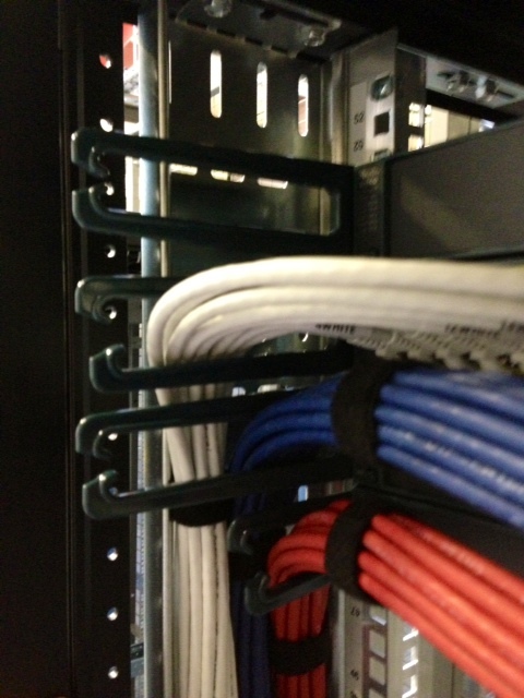
The attached image shows correct routing of the data cords.
-
Have data cords been correctly routed through Switch Arms?
-
Are Velcro ties present in positions 46U, 36U and 21U?<br>
-
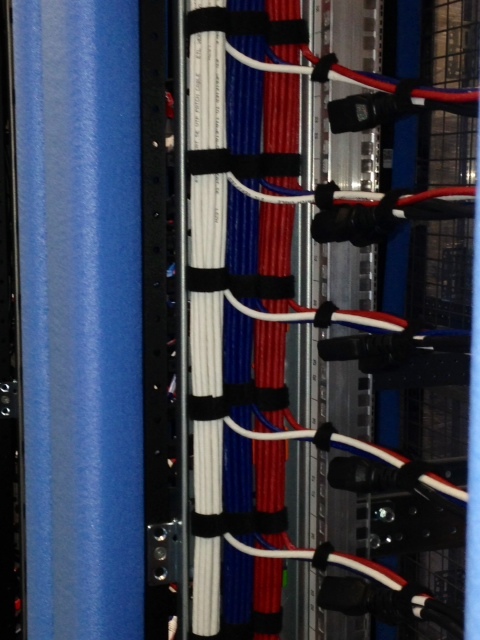
Velcro layout:
-
Are Velcro ties consistent and neat and tidy?<br>
Server Space Cabling
-
Confirm position 2U has the following cords - 1WHITE, 1RED, 1 BLUE and power cords 1A, 1B?<br>
-
Confirm position 4U has the following cords - 2WHITE, 2RED, 2BLUE and power cords 2A, 2B?<br>
-
Confirm position 6U has the following cords - 3WHITE, 3RED, 3BLUE and power cords 3A, 3B?<br>
-
Confirm position 8U has the following cords - 4WHITE, 4RED, 4BLUE and power cords 4A, 4B?<br>
-
Confirm position 10U has the following cords - 5WHITE, 5RED, 5BLUE and power cords 5A, 5B?<br>
-
Confirm position 12U has the following cords - 6WHITE, 6RED, 6BLUE and power cords 6A, 6B?<br>
-
Confirm position 14U has the following cords - 7WHITE, 7RED, 7BLUE and power cords 7A, 7B?<br>
-
Confirm position 16U has the following cords - 8WHITE, 8RED, 8BLUE and power cords 8A, 8B?<br>
-
Confirm position 18U has the following cords - 9WHITE, 9RED, 9BLUE and power cords 9A, 9B?<br>
-
Confirm position 20U has the following cords - 10WHITE, 10RED, 10BLUE and power cords 10A, 10B?<br>
-
Confirm position 22U has the following cords - 11WHITE, 11RED, 11BLUE and power cords 11A, 11B?<br>
-
Confirm position 24U has the following cords - 12WHITE, 12RED, 12BLUE and power cords 12A, 12B?<br>
-
Confirm position 26U has the following cords - 13WHITE, 13RED, 13BLUE and power cords 13A, 13B?<br>
-
Confirm position 28U has the following cords - 14WHITE, 14RED, 14BLUE and power cords 14A, 14B?<br>
-
Confirm position 30U has the following cords - 15WHITE, 15RED, 15BLUE and power cords 15A, 15B?<br>
-
Confirm position 32U has the following cords - 16WHITE, 16RED, 16BLUE and power cords 16A, 16B?<br>
-
Confirm position 34U has the following cords -17WHITE, 17RED, 17BLUE and power cords 17A, 17B?
-
Confirm all Velcro ties are aligned and no cords are dangling
-
Confirm white cable ties are replaced with 10mm Velcro ties
-
The picture shows the SPEC A power routing YELLOW above green
-
BUILD A -confirm YELLOW above GREEN
-
BUILD B - confirm GREEN above YELLOW
Additional Checks
-
The clip on front plate should be positioned as shown:
-
Confirm correct position of front plate
-
The ITM label should be positioned as shown:
-
Confirm correct position of ITM Test Label location at bottom left corner of the cabinet?<br>
-
Have test results been checked and downloaded?
-
Perform visual check?
-
Any other comments:
-
Enter the ITM Cabledesk URL i.e. http://testrm.com/TGQHQ
-
Audit carried out by: