")


TASK EXECUTION │ PROCEDURE / PROCESS
-
The purpose of this SWI is to provide sufficient procedure and information for performing planned online calibration of the underground pump stations electromagnetic flow meters and pressure transmitter. This procedure applies to the Underground pump stations. 40013922PIT6753, 40013922PP3001VALV.FLMC
40013922PIT6754, 40013922PP3002VALV.FLMC
40013922PIT6763, 40013922PP3011VALV.FLMC
40013922PIT6764, 40013922PP3012VALV.FLMC
40013922PIT6773, 40013922PP3021VALV.FLMC
40013922PIT6774, 40013922PP3022VALV.FLMC
40013922PIT6783, 40013922PP3041VALV.FLMC
40013922PIT6784, 40013922PP3042VALV.FLMC
40013922PIT6503, 40013922PP2031VALV.FLMC
40013922PIT6504, 40013922PP2032VALV.FLMC
40013922PIT6513, 40013922PP2051VALV.FLMC
40013922PIT6514, 40013922PP2052VALV.FLMC
40013922PIT6523, 40013922PP2061VALV.FLMC
40013922PIT6524, 40013922PP2062VALV.FLMC
40013922PIT6533, 40013922PP2011VALV.FLMC
40013922PIT6534, 40013922PP2012VALV.FLMC
4001SWDGSTA05 .SK01.PI, 40013922PP2021VALV.FLMC
Approximately 2 Hours. Document number: 10000399288 Effective date: 09/01/2024 Document owner: UG AM Superintendent Site name: Kennecott Underground Department: Asset Management
Please see attached SWI for Underground 4Wk Pump Stations Instrumentation Calibration. -
Please read above attached the SWI for Underground 4WK Pump Station Instrumentation Calibration.
Conducted
-
Conducted on
-
Inspected by
-
Work Order number
-
Location
-
Qualification: Electricians - Trained, competent and authorized for the task.
HEALTH, SAFETY & ENVIRONMENTAL CONSIDERATIONS
Contact with Electricity
-
Contact with Electricity
Please follow below CRM controls
• Flame & Arc Flash-resistant clothing with CAT 2 Rating.
• Identify and control the hazards to complete Critical Control Checklists.
• Avoid contact with live equipment.
• Follow Electrical Safety Procedure.
Slip, trip, and falls
-
• A high standard of housekeeping shall be always maintained to prevent trip hazards.
• Be wary while walking around the pumps, motors, and other live equipment as the area might be slippery. -
Use appropriate PPE
Visibility and lightings
-
Use a headlamp or flashlight when working at the pump station
Force
-
• Regular rest
• Use appropriate tools.
• Avoid using brute force.
• Work in a team and ask for help from others -
Maintain good communication
Work instructions
1. PRE-START PREPARATIONS & ISOLATION (MUST FOLLOW C1 ISOLATION PROCESS)
-
1.1 Identify and control the hazards using the TRACK
-
1.2 Prepare material and tools:<br>Ensure that you have the necessary equipment/tools available at the site:<br>- Required Materials<br>- Required PPE<br>- Maintain good housekeeping<br>Proper Inspection of all tools and equipment
-
“HOLD POINT”
Leader and team members (Subject Matter Expert - SME) must verify the critical control(s) where a critical risk exists -
1.3 Inform the DG supervisor or team lead of the scope of work and that work about to start.

2. ELECTROMAGNETIC FLOW METER INSPECTION
-
2.1 Step Instruction
-
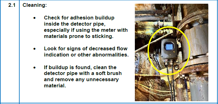
2.1 Cleaning:<br>• Check for adhesion buildup inside the detector pipe, especially if using the meter with materials prone to sticking.<br>• Look for signs of decreased flow indication or other abnormalities.<br>• If buildup is found, clean the detector pipe with a soft brush and remove any unnecessary material.
-
2.2 Calibration Verification (LF62*F Converter only):<br>• Use the built-in Mag-Prover calibrator to verify the original flow lab calibration without needing external tools.<br>• This can be used to check converter zero and span for maintenance or inspections. Mag-Prover Built-In Calibrator<br>• The converter LF62*F has a built-in reference signal calibration and verification circuit that allows you to re-verify the original magmeter flow lab calibration without the need for external devices.<br>• This reference signal can be used to check the zero and span of the converter for the purpose of instrumentation maintenance or periodical inspection. Refer to combined converter's manual.
-
2.3 Step Instruction
-
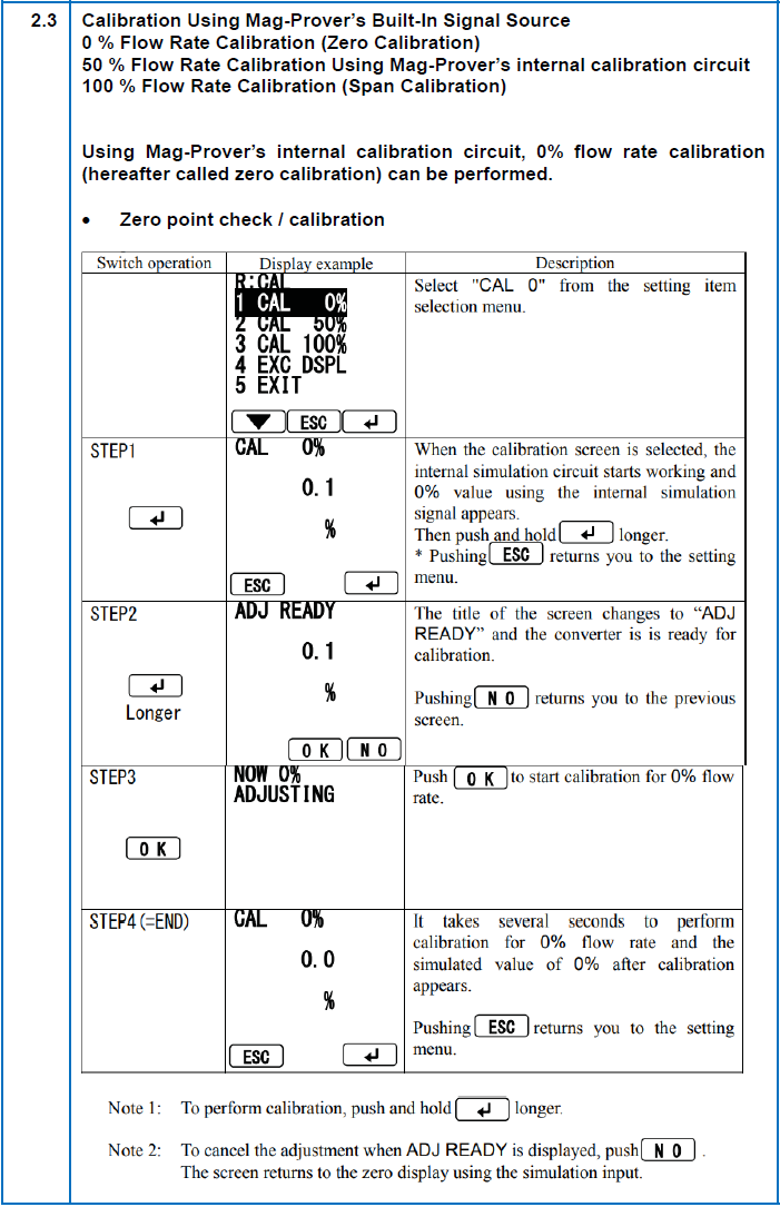
2.3 Calibration Using Mag-Prover’s Built-In Signal Source<br>- 0 % Flow Rate Calibration (Zero Calibration)<br>- 50 % Flow Rate Calibration Using Mag-Prover’s internal calibration circuit<br>- 100 % Flow Rate Calibration (Span Calibration)<br>Using Mag-Prover’s internal calibration circuit, 0% flow rate calibration (hereafter called zero calibration) can be performed.<br>• Zero point check / calibration.
-
2.4 50 % Flow Rate Calibration Using Mag-Prover’s internal calibration circuit<br>Using Mag-Prover’s internal calibration circuit, 50% flow rate calibration can be performed.<br>For calibration procedure, see the calibration procedure for 0% flow rate. (For 50% flow rate calibration, select "CAL 50%" from the setting menu).
-
2.5 100 % Flow Rate Calibration (Span Calibration)<br>Using Mag-Prover’s internal calibration circuit, 100% flow rate calibration can be performed.<br>For calibration procedure, see the calibration procedure for 0% flow rate. (For 100% flow rate calibration, select "CAL 100%" from the setting menu).
-
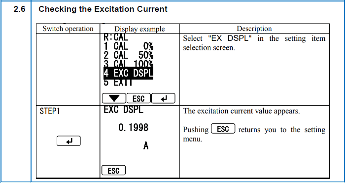
2.6 Step Instruction
-
2.6 Checking the Excitation Current
3. ALIA APT8000 PRESSURE TRANSMITTER CALIBRTION
-
3.1 Step Instruction
-
3.1 Calibration Verification:<br>Automatic Zero Calibration by Push Button
-
3.2 Step Instruction
-
3.2 Look for any physical damage to the transmitter housing, such as cracks, dents, or loose parts.
-
3.3 Step Instruction
-
3.3 Check if the transmitter is securely mounted.
-
3.4 Step Instruction
-
3.4 Inspect the electrical connections for tightness, corrosion, or damage to the wires or terminals.
-
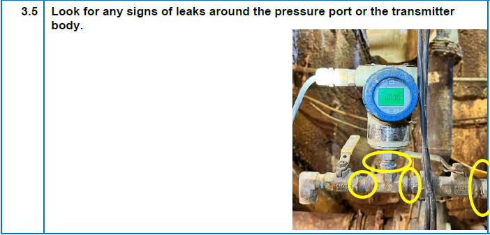
3.5 Step Instruction
-
3.5 Look for any signs of leaks around the pressure port or the transmitter body.
-
3.6 Step Instruction
-
3.6 Wipe the transmitter housing with a clean, damp cloth to remove any dirt or grime.


4. TASK COMPLETION
-
4.1 Clean work area of old or used parts.
-
4.2 Return all unused parts to the warehouse.
-
4.3 Clean and return all equipment and supplies to their proper location.
-
4.4 Clean any used specialty tools and return them to their specified location.
-
4.5 Is the task fully completed? Notify the DG supervisor that the Pump station's electromagnetic flow meters and the pressure transmitters online calibrations are complete, and it is back in operation.
-
4.6 Report any defects to the supervisors and the planning team.<br>Any repair done must also be recorded.
-
ADDITIONAL COMMENTS:
-
Signature
")
")
")
")
")
")
")
")
")