 - For General Use")


Title Page
-
CMS-10-SOP-9014-F12 - 2 and 4 Yearly Cryogenic Vessel Inspection incl AS3788 Fitness for Service
State regulations mandate that pressure equipment must be inspected on a regular basis by a competent person. AS3788 is the Australian standard covering pressure equipment inspection.
As well as covering AS1894 and general This inspection includes sections to ensure we meet this obligation and follow the inspection requirements of AS3788. -
Customer:
-
Customer Address:
-
Specific Vessel Location:
-
Vessel number:
-
Vessel Contents:
-
Vessel Size/Capacity (kL):
-
Manufacturer:
- Armstrong Holland
- BTCE
- CEM
- Chart (China)
- Chart (USA)
- CIMC
- Cryeng
- Cryofab
- Cryolor
- Engineering Valves and Fittings
- Inox
- Johnson Engineering
- Linde
- Metro Engineering
- MVE
- Pioneer Cryogenics
- Taylor Wharton
- Toledo Engineering
- VRV
- Other
-
Specify Manufacturer:
-
Serial Number:
-
Coregas WO no:
-
Date of inspection:
-
Technician (Name):
VESSEL INSPECTION
-
Notes:
- The inspection frequency is 24 monthly except where indicated.
- Some elements of this inspection are required to meet statutory obligations.
- Make good any deficiencies where practical.
- Do not change answers to a positive response after rectification. Instead, add a note detailing the action.
- This checklist is carried out in accordance with AS2896, AS1210, AS1894, AS1319, AS4332, AS1271, AS3788 and WHS legislation
- Add notes and photos where appropriate
1.0 Preliminary Inspection Component
-
1.1 Record the Vessel Pressure upon arrival (kPa): If this is the normal operating pressure, upon completion of the inspection, the vessel pressure should be returned to this setting if it has been changed as a result of any inspection activities.
-
1.2 Record the Vacuum reading - (mTorr)
-
1.3 Is this vacuum reading acceptable ?<br><br>- Perlite Insulated Vessels<br> - Good = 50 mTorr or lower<br> - Average = Between 50 and 100 mTorr<br> - Poor = 100 mTorr or higher (pump down if possible)<br><br>- Multi Layer Insulated Vessels (Microbulk)<br> - Good = 5 mTorr or lower<br> - Average = Between 5 and 20 mTorr<br> - Poor = 20 mTorr or higher (Notify TS Manager - pump down may be required, but might require specialist pumps and/or elevated access)<br><br>- If pump down is required, it is recommended to start this now (if practical) and pump down while the remainder of the inspection is completed. <br><br>- If a vacuum reading is 1000 mTorr (DV6 head) this suggests a serious leak, or a faulty gauge. Refer to TS Manager<br>- If this is an Oxygen vessel reading above 1000 mTorr, DO NOT CONNECT A NON-OXYGEN COMPATIBLE VACUUM PUMP.
-
1.3.1 Are you pumping down the vacuum during this visit?
-
Recommendation is to setup and commence pump-down now so evacuation continues throughout the inspection process.
-
1.3.2 Come back to this question at the completion of the Inspection - Is the pump down complete, or does it require further evacuation?
-
1.3.3 Vacuum Reading - Final (mTorr)
-
1.3.2.1 Progress Vacuum Reading (mTorr)
2.0 4 Yearly Maintenance Tasks
-
Is this a 2 Yearly or 4 Yearly Inspection ?
-
The 4 Yearly Inspection requires replacement of all relief devices
- Main Vessel Safety Valves
- Main Vessel Line Safety Valves
- Vapouriser Safety Valves
- Customer supply line safety valves
- Flow control manifold safety valves
Do not complete questions relating to condition of relief devices, unless some existing devices are retained.
2.1 Replace VESSEL safety valves during 4 Yearly Inspection
-
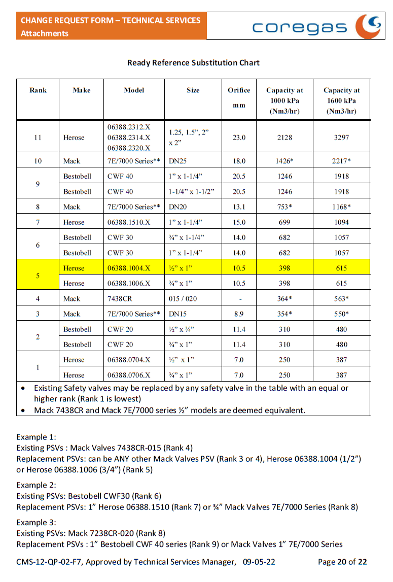
- MUST be like for like unless otherwise allowed under MOC 39298 and MOC 36320 (summary guides attached below)
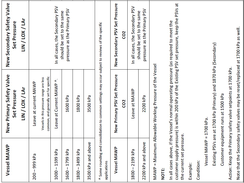
- Primary SV Set pressure must be no higher than the vessel MAWP
- Note that it may be set lower than MAWP. See table below for preferred PSV setting
- Existing Safety Valves are not to be retested in the field without prior approval from the TS Manager.
- If Field Testing is to be done, it must be by trained and Authorised technicians only, and must use approved and calibrated equipment to the standard operating procedure CMS-10-SOP-9019 and in accordance with AS3788 Section 4.7 -
-
-
Are you replacing any VESSEL safety valves?
-
Note the reason why vessel safety valves could not be replaced:
-
Note the reason why some safety valves could not be replaced:
2.1.1 Add NEW Vessel Safety Valve Details Here
-
Tag / ID#
-
Test Certificate Number
-
Make
-
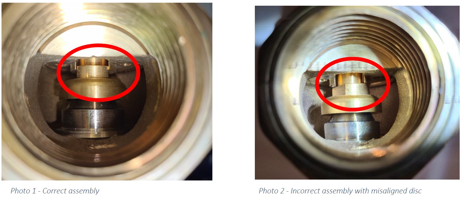
For each new Herose Safety Valves, confirm that the disc stem is sitting within the disc-guide, allowing proper function (refer to images below)<br><br>- If not, IMMEDIATELY NOTIFY TECHNICAL SERVICES MANAGER AND REPLACE COMPROMISED VALVES<br>- Non-functioning valves in this condition must be removed and sent to the Tech Services Manager for investigation - DO NOT RESET AND REUSE
-
Herose Safety Valve disc alignment
-
Model
-
Specify Model
-
Specify Model
-
Size
-
Thread type
-
Set Pressure
-
Serial #
2.2 Replace all LINE RELIEF VALVES on VESSEL PIPING during 4 Yr Inspection
-
- Replacements MUST be like for like.
- Lower pressure may be used if required, but must be checked for suitability with downstream process (refer to TS Manager)
- Ensure that all newly installed safety devices are properly tagged with the Set Pressure and Test Date and/or Next Test Date (4 years from installation) -
Are you replacing any LINE RELIEF VALVES on the Vessel?
-
Note the reason why vessel safety valves could not be replaced:
-
Note the reason why some safety valves could not be replaced:
2.2.1 Add details for New LINE RELIEF VALVES on VESSEL PIPING
-
Tag / ID#
-
Test Certificate Number
-
Make
-
For each new Herose Safety Valves, confirm that the disc stem is sitting within the disc-guide, allowing proper function (refer to images below)<br><br>- If not, IMMEDIATELY NOTIFY TECHNICAL SERVICES MANAGER AND REPLACE COMPROMISED VALVES<br>- Non-functioning valves in this condition must be removed and sent to the Tech Services Manager for investigation - DO NOT RESET AND REUSE
-
Herose Safety Valve disc alignment
-
Model
-
Specify Model
-
Specify Model
-
Size
-
Thread type
-
Set Pressure
-
Serial #
2.3 Replace all LINE RELIEF VALVES on the FLOW CONTROL & CUSTOMER SUPPLY line during 4 Yearly Inspection
-
- Replacements MUST be like for like.
- Lower pressure may be used if required, but must be checked for suitability with downstream process (refer to TS Manager) -
Are you replacing any LINE RELIEF VALVES on the Flow Control and Customer Supply Line?
-
Note the reason why vessel safety valves could not be replaced:
-
Note the reason why some safety valves could not be replaced:
2.3.1 Add Details of New LINE RELIEF VALVES on the Flow Control & Customer Supply Line
-
Tag / ID#
-
Test Certificate Number
-
Make
-
For each new Herose Safety Valves, confirm that the disc stem is sitting within the disc-guide, allowing proper function (refer to images below)<br><br>- If not, IMMEDIATELY NOTIFY TECHNICAL SERVICES MANAGER AND REPLACE COMPROMISED VALVES<br>- Non-functioning valves in this condition must be removed and sent to the Tech Services Manager for investigation - DO NOT RESET AND REUSE
-
Herose Safety Valve disc alignment
-
Model
-
Specify Model
-
Specify Model
-
Size
-
Thread type
-
Set Pressure
-
Serial #
-
2.1.2 Move on to Statutory Safety Valve Visual Inspection
-
*** 4 Yearly Only Maintenance Tasks are now complete. Move on to Statutory Safety Valve Inspection for any valves NOT REPLACED ***
3.0 Statutory Safety Valve Visual Inspection
-
Please confirm the type of inspection
- 2 Yearly
- 4 Yearly (All SV have been changed)
- 4 Yearly (Only some/none SV have been changed)
-
All safety devices must be visually inspected unless they have already been replaced.
-
For a 4 Yearly Inspection, all Safety Valves should be replaced, so visual inspection is not required except for any devices which have not been replaced. Move on to Q3.5
-
3.1 Are all Safety valves in test (within 5 years of last test per AS3788) and tagged with the correct operating pressure. (Coregas standard test frequency is 4 years)<br><br>- Any safety device which is not tagged, must be replaced.
-
3.2 Record details of Existing (In-Service) Safety Valve (Vessel Main Safeties and All Line Reliefs up to the battery limit)
3.2.1 VESSEL RELIEF VALVES - Record details of EACH Existing (In-Service) Safety Valve on the Vessel (2 x Primary + 2 x Secondary) -
Tag No (per P&ID) and description of position Correct the actual tag number if it does not match the schematic.
-
Valve Make and Model
-
Model
-
If Other - specify Model No:
-
Model
- 7438CR
- 7E Series
- 7228 CR
- 7238 CR
- 7248 CR
- 7628 CR
- 7638 CR
- 7648 CR
- Other
- Unsure
-
If Other - specify Model No:
-
Model
-
If Other - Specify Model No
-
Specify Model:
-
Please specify the Make and Model
-
Inlet Thread Size and Type - Herose Codes are on Inlet Body Hex face - G = BSP Parallel (eg. G 3/4 = 3/4" BSP Parallel thread - R = BSP Taper (eg. R 1/2 = 1/2" BSP Taper - 1/2" NPT - Mack Valves - 015 = 1/2" BSPT - 020 = 3/4" BSPT
-
Serial No.
-
Set Pressure
-
Last Test Date (if marked)
-
Next Test Date (if marked)
(Exclude any Safety Valves replaced during the inspection where those details are recorded elsewhere)
3.2.2 VESSEL PIPING LINE RELIEF VALVES
-
3.2.2 VESSEL PIPING LINE RELIEF VALVES - Record details of EACH Existing (In-Service) Line Relief Valve on the Vessel Piping
-
Tag No (per P&ID) and description of position Correct the actual tag number if it does not match the schematic.
-
Valve Make and Model
-
Model
-
If Other - specify Model No:
-
Model
- 7438CR
- 7E Series
- 7228 CR
- 7238 CR
- 7248 CR
- 7628 CR
- 7638 CR
- 7648 CR
- Other
- Unsure
-
If Other - specify Model No:
-
Model
-
If Other - Specify Model No
-
Specify Model:
-
Please specify the Make and Model
-
Inlet Thread Size and Type - Herose Codes are on Inlet Body Hex face - G = BSP Parallel (eg. G 3/4 = 3/4" BSP Parallel thread - R = BSP Taper (eg. R 1/2 = 1/2" BSP Taper - 1/2" NPT - Mack Valves - 015 = 1/2" BSPT - 020 = 3/4" BSPT
-
Serial No.
-
Set Pressure
-
Last Test Date (if marked)
-
Next Test Date (if marked)
(Exclude any Safety Valves replaced during the inspection where those details are recorded elsewhere)
3.2.3 CUSTOMER SUPPLY / FLOW CONTROL LINE RELIEF VALVES
-
Tag No (per P&ID) and description of position Correct the actual tag number if it does not match the schematic.
-
Valve Make and Model
-
Model
-
If Other - specify Model No:
-
Model
- 7438CR
- 7E Series
- 7228 CR
- 7238 CR
- 7248 CR
- 7628 CR
- 7638 CR
- 7648 CR
- Other
- Unsure
-
If Other - specify Model No:
-
Model
-
If Other - Specify Model No
-
Specify Model:
-
Please specify the Make and Model
-
Inlet Thread Size and Type - Herose Codes are on Inlet Body Hex face - G = BSP Parallel (eg. G 3/4 = 3/4" BSP Parallel thread - R = BSP Taper (eg. R 1/2 = 1/2" BSP Taper - 1/2" NPT - Mack Valves - 015 = 1/2" BSPT - 020 = 3/4" BSPT
-
Serial No.
-
Set Pressure
-
Last Test Date (if marked)
-
Next Test Date (if marked)
-
3.3 Is the VESSEL PRIMARY Safety Valve set pressure less than or equal to the vessel MAWP<br>- Note that it may be set lower than the MAWP. See table below for preferred PSV setting
-
-
3.4 Is the Vessel SECONDARY Safety Valve set pressure NO HIGHER than the vessel MAWP x 1.1 ?<br><br>- This may be set at the same pressure as the Primary Safety Valve<br>- if MAWP = 1600 kPa then Maximum Secondary SV set pressure = 1760 kPa<br>- if MAWP = 1700 kPa then Maximum Secondary SV set pressure = 1870 kPa<br>- if MAWP = 1800 kPa then Maximum Secondary SV set pressure = 1980 kPa<br>- if MAWP = 1900 kPa then Maximum Secondary SV set pressure = 2090 kPa<br>- if MAWP = 2200 kPa then Maximum Secondary SV set pressure = 2420 kPa<br>- if MAWP = 2400 kPa then Maximum Secondary SV set pressure = 2640 kPa<br>- if MAWP = 3700 kPa then Maximum Secondary SV set pressure = 4070 kPa
-
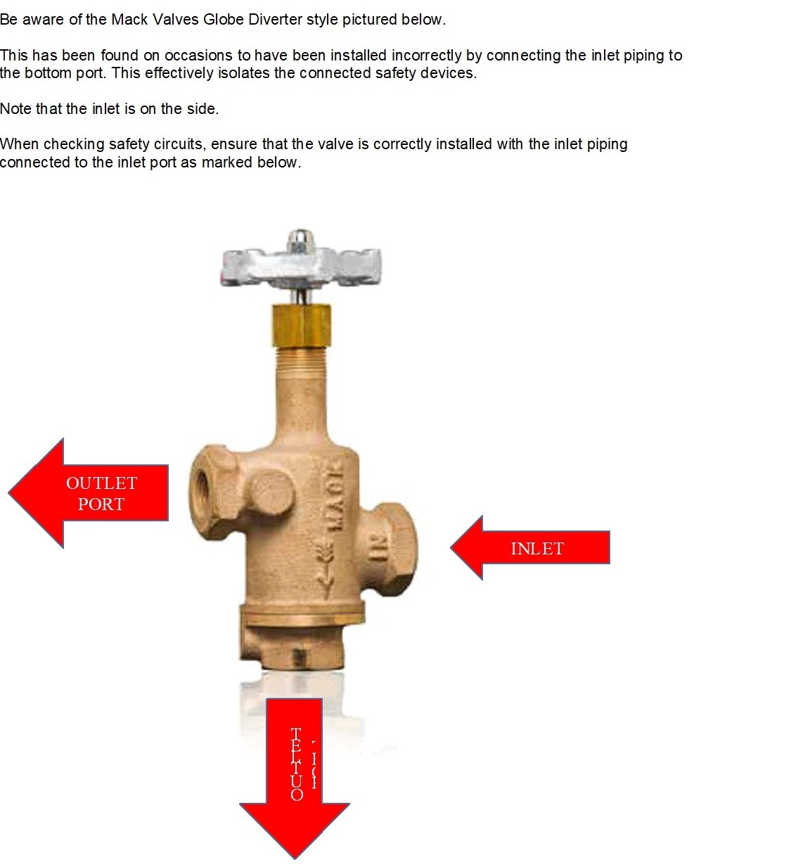
3.5 Is the Safety circuit 3-WAY-VALVE operable and piped correctly. See guides below.<br><br>- Check flow indicators (marked on the valves) where fitted. <br>- Ensure that the line to the vessel is connected to the marked Inlet.<br>- Pay Particular attention to Mack Valves Globe style with 2 outlets (refer to attachment for correct plumbing)<br>- Note any Ball Diverters with end connections (rather than top and bottom). Gather details and photos of the diverter model and Report back to Technical Services Engineering for review.<br>
-
-
-
3.6 Correct Installation of Safety valves
-
3.6.1 Are the Safety valves are all mounted upright
-
3.6.2 Are all Safety valves fitted with suitable flow directing elbows (to direct flow downwards), or otherwise have their flow directed downwards or piped away to a safe location
-
3.6.3 Are the main vessel safety valve outlets fitted with Extended discharge pipes ?
-
3.6.3.1 If main vessel safety valve outlets are not fitted with extended outlets, should they be?<br><br>- eg. where discharge impinges on other valves or presents a hazard to nearby personnel
-
3.6.4 Safety valves or discharge pipes are bracketed or braced together
-
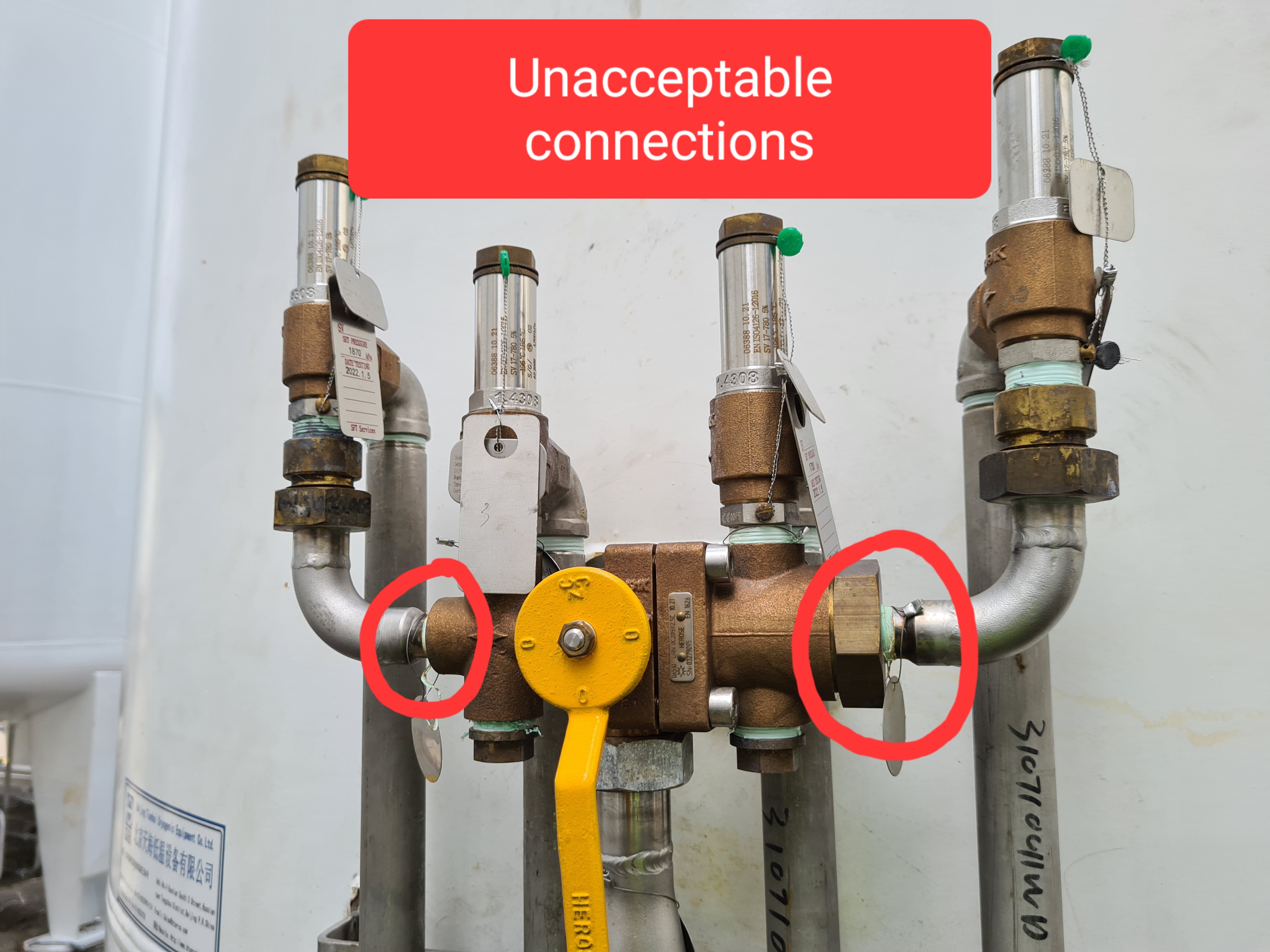
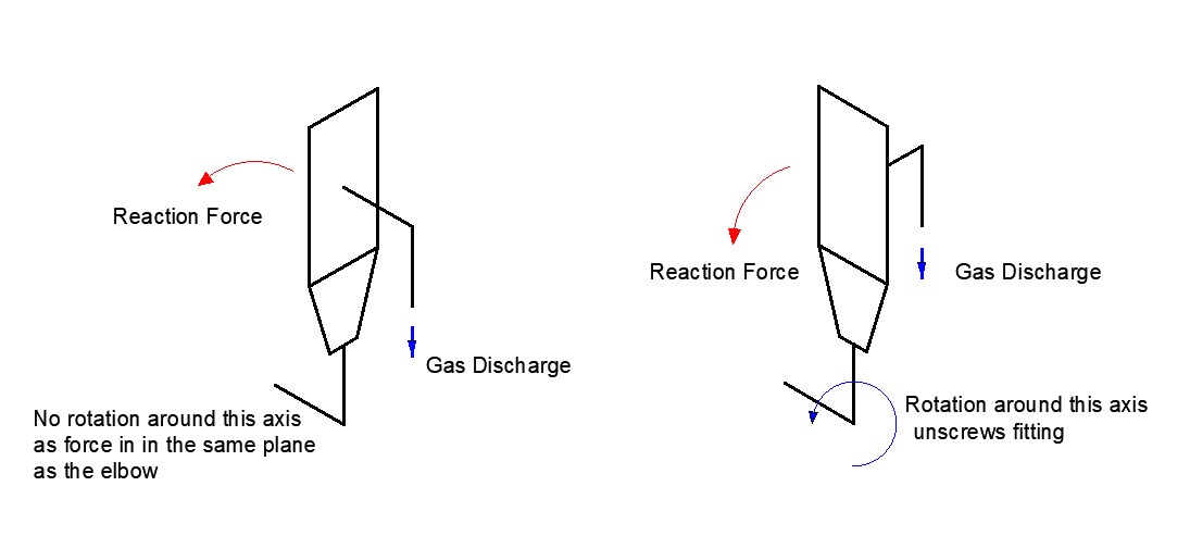
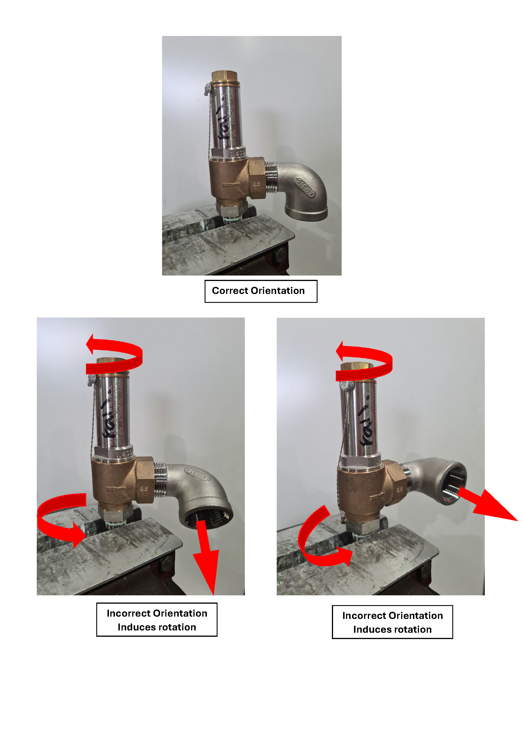
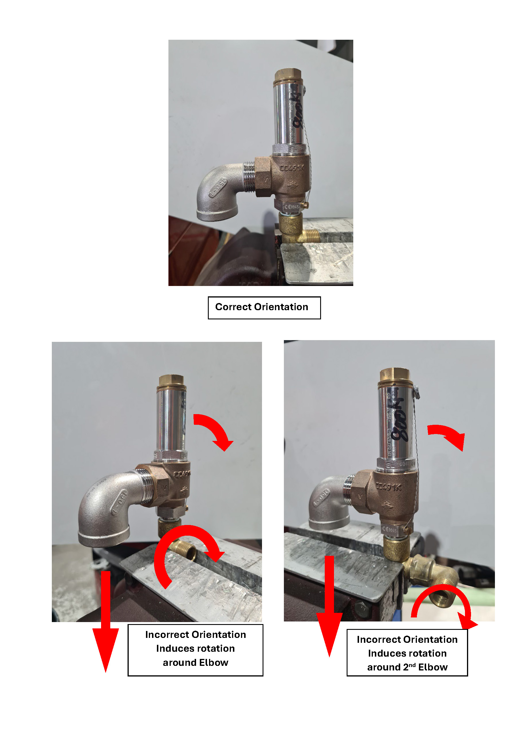
3.6.5 Are Safety Valves prevented from rotating around the inlet thread or other inlet fittings, due to discharge reaction forces? - Outlet elbows are in the same plane as any inlet elbow - Adequately bracketed (ie. discharge cannot cause the SV to spin around a fitting) - Be aware of screwed elbows and joiners on inlets. Discharging gas may cause rotation of elbows.
- Yes - Forces do not create rotation potential
- Yes - Rotation is prevented by bracketing
- No - Rotation is possible
-
-
-
-
3.6.6 Discharge does not impinge on other valves, outer shell, or structural component (eg. vessel leg)
-
3.7 Is a Vapouriser installed as part of this system
-
3.7.1 What is the vapouriser size (no. of fins x height)
-
3.7.2 Is there only a single line relief valve protecting the vapouriser, or is there a changeover valve and second line relief valve?
- Single Line Relief
- Changeover valve with Dual Line Reliefs
-
3.7.3 What are the tag numbers and/or serial numbers of the safety valves protecting the vapouriser (relief valves immediately downstream of the vapourisers) as detailed in Q3.1.1
-
3.8 Satisfactory Condition of Safety Valves
-
3.8.1 Lock wire seals are all in place
-
Safety valves with wire seals missing must be treated as if compromised. They must be replaced and the old valve(s) returned to the TS Manager
-
3.8.1.1 Confirm that Safety valves with missing or broken wire seals have been replaced
-
Note reason why this has not been replaced during this inspection:
3.8.1.2 Add NEW Safety Valve Details Here
-
Tag / ID#
-
Make
-
For each new Herose Safety Valves, confirm that the disc stem is sitting within the disc-guide, allowing proper function (refer to images below)<br><br>- If not, IMMEDIATELY NOTIFY TECHNICAL SERVICES MANAGER AND REPLACE COMPROMISED VALVES<br>- Non-functioning valves in this condition must be removed and sent to the Tech Services Manager for investigation - DO NOT RESET AND REUSE
-
Herose Safety Valve disc alignment
-
Model
-
Specify Model
-
Specify Model
-
Size
-
Thread type
-
Set Pressure
-
Serial #
-
3.8.2 Check for any damage or deterioration of safety valves
-
Safety Valves showing signs of damage which may affect the operation, must be replaced and the damaged valves returned to the TS Manager
-
3.8.2.1 Confirm that damaged Safety Valves have been replaced
-
3.8.2.2 Note reason why damaged valve(s) have not been replaced during this inspection:
3.8.2.2 Add NEW Safety Valve Details Here
-
ID#
-
Make
-
For each new Herose Safety Valves, confirm that the disc stem is sitting within the disc-guide, allowing proper function (refer to images below)<br><br>- If not, IMMEDIATELY NOTIFY TECHNICAL SERVICES MANAGER AND REPLACE COMPROMISED VALVES<br>- Non-functioning valves in this condition must be removed and sent to the Tech Services Manager for investigation - DO NOT RESET AND REUSE
-
Herose Safety Valve disc alignment
-
Model
-
Specify Model
-
Specify Model
-
Size
-
Thread type
-
Set Pressure
-
Serial #
-
3.8.3 Safety Valve Outlets are clear of insect nests or other blockages<br><br>- discharge pipes and elbows must be removed to allow proper inspection<br>- a boroscope may be used if available and it provides clear detail of all inspection points
-
3.8.4 Safety Valve Bracing is adequate - does not allow for vibration or discharge induced unscrewing
-
3.8.5 If easing gear is fitted - lift lever and check for flow
-
3.8.6 Herose Safety Valves - is the disc stem sitting within the disc-guide, allowing proper function (refer to images below)<br><br>- If not, IMMEDIATELY NOTIFY TECHNICAL SERVICES MANAGER AND REPLACE COMPROMISED VALVES<br>- Non-functioning valves in this condition must be removed and sent to the Tech Services Manager for investigation - DO NOT RESET AND REUSE<br>- If replacement valves are not available, contact the Technical Services Manager immediately. The vessel MUST be made safe. <br><br>- Consider swapping safety valves on the diverter valve to achieve one side being safe, and locking out the diverter valve to prevent changeover to the side with the compromised valve(s).<br><br>- If no immediate resolution is possible, it may be necessary to depressurise the vessel and Tag it OUT OF SERVICE.
-
Herose Safety Valve disc alignment
-
3.8.7 Is there anything else observed which is of concern.
-
Note any additional comments or concerns:
3.2.3 CUSTOMER SUPPLY / FLOW CONTROL LINE RELIEF VALVES - Record details of EACH Existing (In-Service) Line Relief Valve on the Customer Supply line and flow control.
(Exclude any Safety Valves replaced during the inspection where those details are recorded elsewhere)
4.0 Statutory Vessel External Inspection Component
-
4.1 Is the VESSEL DATA PLATE present and legible?<br><br>- be aware that some older vessels have 2 data plates, one of which is often a welded patch and may be heavily covered by paint. If present, this should be cleaned or stripped back so it can be read.
-
4.2 General condition of the Vessel : Outer vessel and pipework (refer to AS3788 Section 4.4 and Appendix D)
-
4.2.1 Vessel is free of visible cold spots or sweating
- No visible cold spots or sweating
- Visible cold spots / sweating
-
4.2.2 Vessel shell is free of damage or deterioration beyond normal wear and tear
-
4.2.3 Pipework and valves are free of damage
-
4.2.4 Vessel main support legs / base, transport legs and lifting lugs are free of damage
-
4.2.5 Brackets and attachments are free of damage
-
4.2.6 Any Hold down bolts or clamps fitted are tight
-
4.2.7 No visible cracks in accessible outer vessel SHELL welds
-
4.2.8 No visible cracks in outer vessel PIPE PENETRATION welds
-
4.2.9 No visible cracks in MAIN SUPPORT LEG TO SHELL welds
-
4.2.10 Outer vessel SAFETY HEAD condition - Due to the location of the safety head, this can be difficult to determine. - If a weather cap is fitted, there is a high chance that the safety head condition is unchanged from installation - confirm it is not clamped, taped, or otherwise restricted from lifting - confirm no heavy rusting is visible - smaller vessels may be inspected using a suitable ladder or EWP (if available) - it may be possible to partially inspect using binoculars from a short distance away or nearby vantage point.
- Fully viewed - Appears to be acceptable
- Inspection limited but Appears acceptable
- Appears to be compromised
- Inspection not possible or inconclusive
-
4.3 Corrosion: absent or not excessive.
-
4.3.1 Vessel SHELL and HEADS are free of EXCESSIVE corrosion <br><br>- check 360° around vessel, under vessel, on top of vessel where possible (look for nearby vantage point such as buildings or roofs)<br>- Minor corrosion should be treated where possible to prevent further deterioration
-
4.3.2 VESSEL LEGS and FEET are free of excessive corrosion
-
4.3.3 DOUBLER PADS have WEEP HOLES (if fitted) which are sealed (with silicone or similar)
-
4.3.4 Areas BEHIND DATA PLATES are free of corrosion. Any sealant used on closely mounted plates is in good condition.
-
4.4 Condition of the vessel foundations and supports is acceptable (refer to AS3788 Appendix Z)
-
4.4.1 Check for subsidence, cracking, deterioration, exposure and/or corrosion of concrete reinforcing
-
4.4.2 Check that bolting/clamping to foundations is present and in good condition, no excessive corrosion)<br>- At least 1 bolt per leg up to 30kL (non cyclone region)<br>- At least 2 bolts per leg over 30kL (non-cyclone region) or 15kL and over in cyclone regions
-
4.4.3 Check that the vessel is plumb - if there is any deviation, check that it is not due to slab movement <br>- use a long straight edge and spirit level to remove deviations created by shell bulges or distortion<br>- allowable deviation (per API653) between the top and bottom of the shell is 1/100th of the overall height<br>- For a 2m long straight edge, this is equivalent to a 20mm difference. ie the top (or bottom, depending on the direction of the lean) of the straight edge is 20mm from the shell when plumb
-
4.4.4 If a steel plate is used, check for excessive corrosion, slip hazards, bending or buckling
-
4.4.4.1 If a steel plate is used, is it painted?
-
4.4.5 Check vessel legs for cracks, impact damage, bending, evidence of cryogenic liquid impingement
5.0 AS1894 Compliance and General Inspection Component
-
5.1 Is the vessel Outdoors ?
-
5.1.1 If Unsure, provide details of why it may not be defined as Outdoors. Include Photos and relevant dimensions.
-
Ventilation is required for vessels in poorly ventilated areas or indoors (refer to AS1894 Section 3.5.4)
-
5.1.2 What product does this vessel contain?<br> (Liquid oxygen MUST be located outdoors)
-
5.2 Is this Inert Gas vessel adequately ventilated by one (or more) of the following. - Forced ventilation - Natural Ventilation Openings - Sited against an external meshed wall - Sufficient room volume to prevent Oxygen depletion - As a last resort - Oxygen monitoring and robust access procedures (ie. not possible to enter the space with an oxygen deficient atmosphere, or at least without clear and assured warning when it is unsafe to enter. Refer to AS1894 for more information and details of each compliance method If more than one method is applicable, note the main method here
- Forced Ventilation
- Natural Ventilation Openings
- Vessel sited against an external meshed wall
- Sufficient room volume
- Oxygen monitoring and strict procedures
- None of the above apply
-
5.2.1 Is forced ventilation used ? Is it adequate and operating correctly (requires 10m3/min per 1200L vessel volume)
- Adequate Forced Ventilation
- Forced Ventilation claimed as protection, but inadequate or rate not known
- No Forced Ventilation
-
Note extraction rate if known:
-
5.2.2 Are there adequate natural ventilation openings (10m2 in and 10m2 out per 1200L vessel volume)
- Adequate Openings
- Openings claimed as ventilation method, but too small
- No Openings
-
Note details of openings and their dimensions:
-
5.2.3 Is the vessel sited against an external wall with mesh or louvered openings at least as wide as the vessel and as high as the safety valves?
-
5.2.4 Is the total volume of the enclosed space large enough to prevent Oxygen depletion? - General rule of thumb to stay above 19.0% Oxygen: Room Volume (m3) / 7 = Max LIN Volume (L) Room Volume (m3) / 9 = Max LAr Volume (L) Room Volume (m3) / 6 = Max LCO2 Volume (L)
- Yes (claimed as compliance method)
- No (but claimed as compliance method)
- Not claimed as compliance method
-
If claimed as compliance method then provide room dimensions L x W x H and Photos
-
Room Width (m)
-
Room Length (m)
-
Room Height (m)
-
Room Volume (m3)
-
Maximum LIN Vessel Volume Permitted (Litres) =
-
Maximum LAR Vessel Volume Permitted (Litres) =
-
Maximum CO2 Vessel Volume Permitted (Litres) =
-
Is the vessel size smaller than the maximum size allowed as calculated in the previous question?
- Yes - smaller than maximum allowed
- No - Larger than the maximum allowed
-
5.2.5 Is a working oxygen depletion monitor fitted ?
-
5.2.6 If an oxygen monitor is NOT fitted, is it safe without one?
-
Liquid Oxygen vessels are not permitted in locations defined as Indoors
-
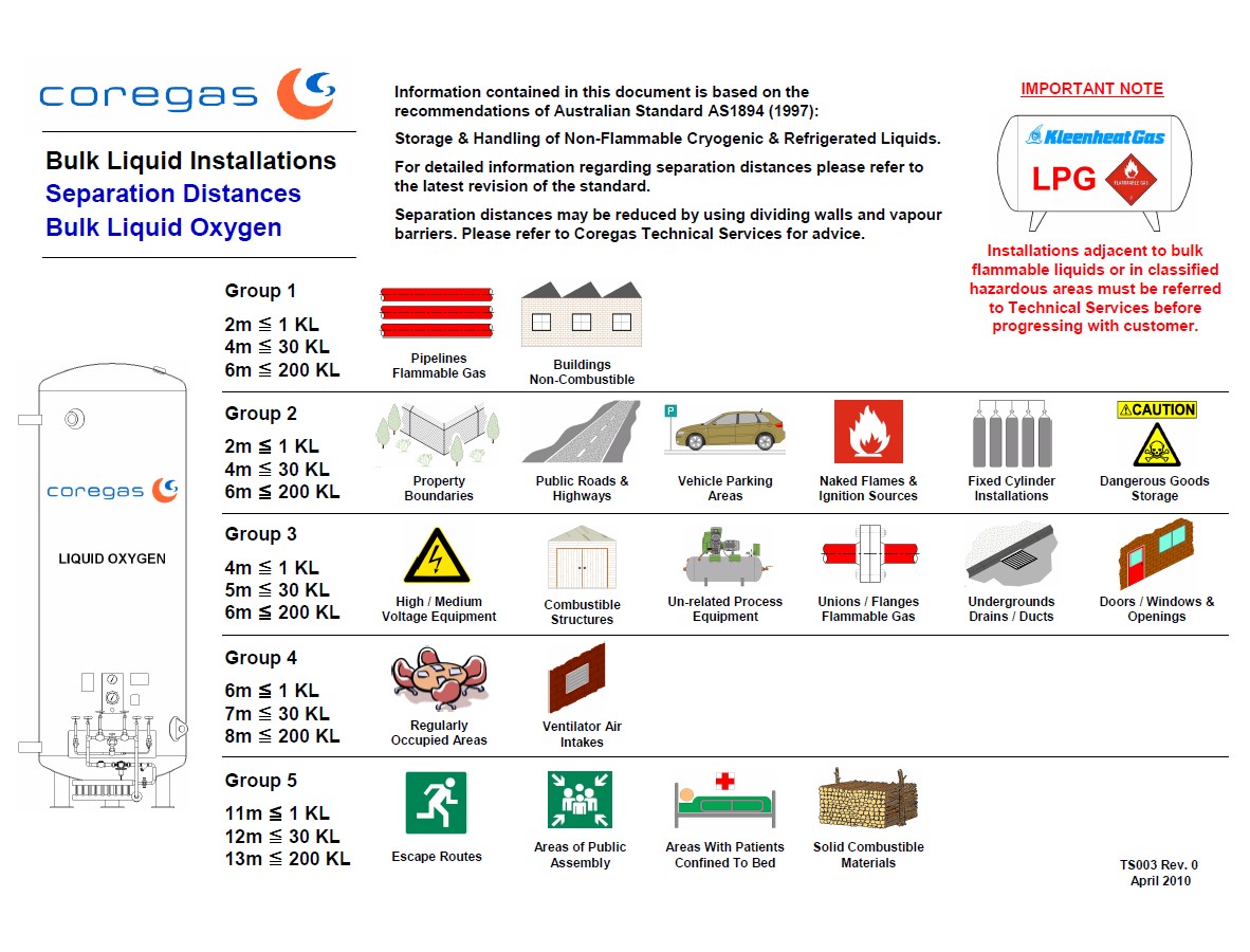
5.3 Separation distances for Oxygen are acceptable (refer to Chart below and AS1894 Table 4.1)
-
-
5.3.1 Oxygen vessel – concrete tanker hard stand (min 2.5m x 2.5m) with no filled expansion joints is in place (refer AS1894 Section 4.4)
-
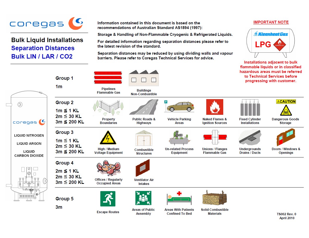
5.4 Separation distances for Inert Gases are acceptable (refer to Chart below and AS1894 Table 5.1)
-
-
5.5 Bollards / impact protection is in place where required, is suitably rated, and is in good order (refer to AS1894 Section 3.5.2 and Appendix D)<br><br>- The design should be at least equivalent to W Guardrail-type highway crash barrier<br>- Posts or old cylinders with bolted baseplates are not usually adequate protection
-
5.6 General cleanliness of the overall compound (refer to AS1894)<br><br>- Free from rubbish, organic matter, chemical contamination, combustible materials, other Dangerous Goods, moss build up on the ground, items or equipment that are not part of the installation.
-
5.7 PRODUCT LABEL is present and legible (should be positioned roughly above the Contents Gauge)<br><br>(ie. says: Liquid Nitrogen, Liquid Oxygen, Liquid Argon, or Liquid Carbon Dioxide, etc)
-
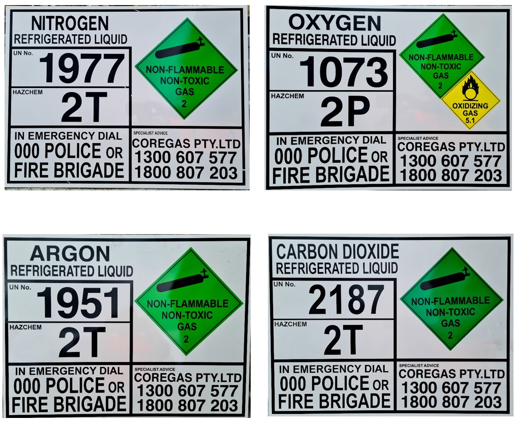
5.8 EMERGENCY INFORMATION PANEL is present, correct, in good condition.<br><br>Refer to ADGC and attachment below for correct details
-
-
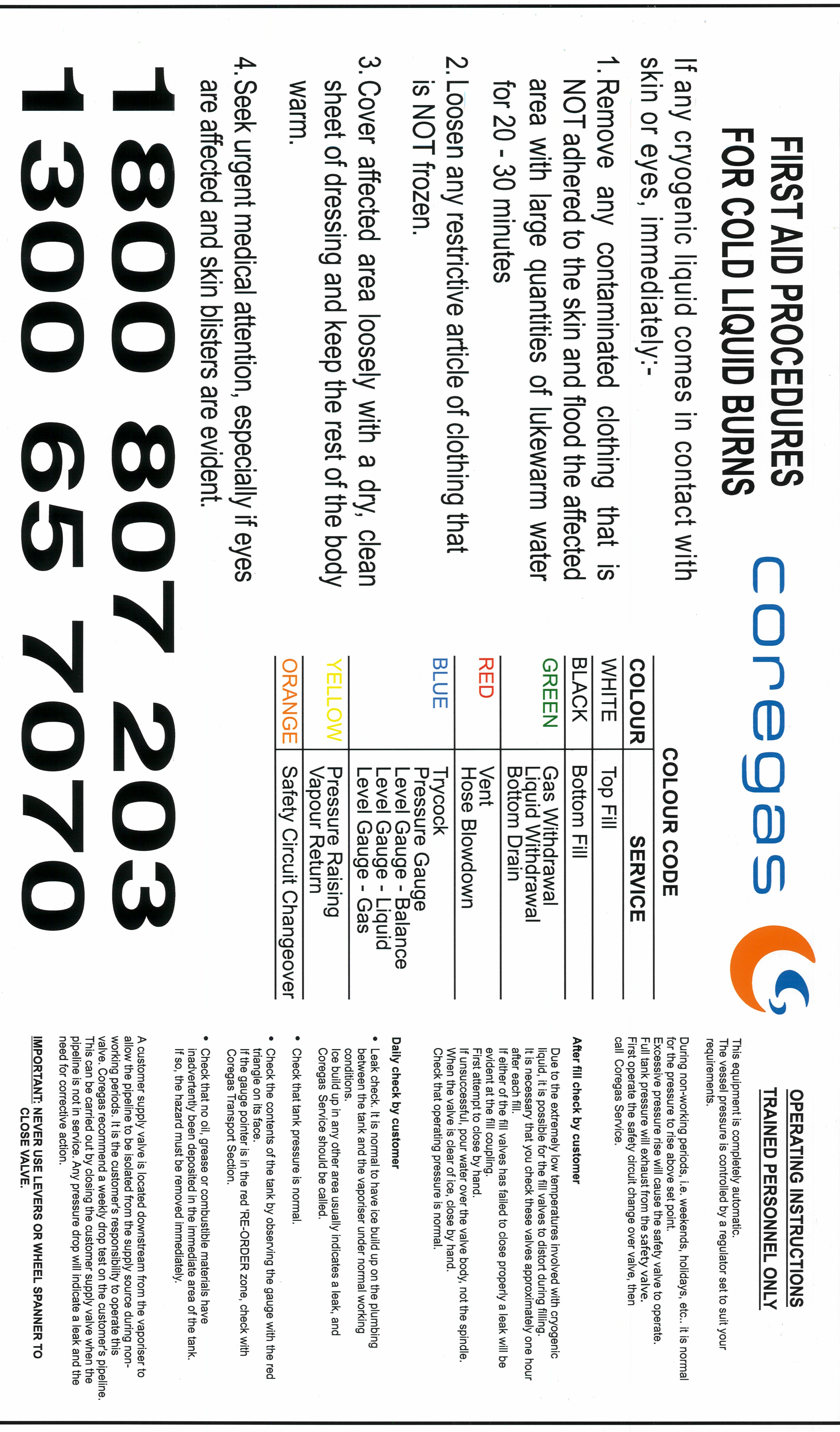
5.9 EMERGENCY PHONE NUMBERS are present, correct and legible on the EIP<br>Emergency – 1300 607 577<br>Business Hrs – 1800 807 203<br>
-
5.10 HAZCHEM signage is present and correct<br><br>- "HAZCHEM" in 100mm high red letters on white or silver background (at every site entrance where Emergency Services may enter). This is a Site Owner responsibility.<br>
-
5.11 Is this an Oxygen or Nitrous Oxide Vessel ?
-
5.11.1 Is the required Safety Signage in place:<br><br>DANGER: NO SMOKING, NO FLAME (or similar)
-
Is the required Safety Signage in place :<br><br>WARNING: RESTRICTED AREA, AUTHORIZED PERSONNEL ONLY (or similar)
-
5.12 Do you THINK that there is sufficient additional SAFETY SIGNAGE present ? See examples below.<br><br>Other than those listed above, there is currently no prescribed signage for our installations, but Safe Work Australia says:<br>Safety signs are required at workplaces that store hazardous chemicals. <br>Safety signs provide information to workers and visitors about how they can manage risks from hazardous chemicals. <br>Safety signs are a risk control measure for using, handling, generating and storing hazardous chemicals. <br>A safety sign has: <br>- warnings about hazards <br>- information about a particular person’s responsibilities with a hazardous chemical. <br><br>Eg. - <br>- "Warning - Risk of Asphyxiation" or similar (for inert gases in poorly ventilated/indoor spaces)<br>- "Danger - Oxygen Enriched Atmosphere May Be Present" (where oxygen may accumulate)<br>- "Warning - Extremely Cold Surfaces" (where there is a chance for unauthorized personnel to contact)<br>- PPE Pictograms (for example if anyone other than Coregas personnel access the compound)<br>- "Keep area Clean and Tidy" (if rubbish or debris might naturally collect in the compound)<br>- "Keep Area Clear" (if likelihood of materials being stored in or around the compound, hindering access)<br>- "Warning - Sudden loud noise" (if safety valves are anticipated to activate regularly)
-
Please provide details and recommendations:
-
5.13 Remote fill point (if fitted) allows line of sight to vessel gauges (refer to AS1894 Section 3.9.3), or if no line of sight, then vessel controls are duplicated (trycock, level and pressure gauges, top and bottom fill valves)
-
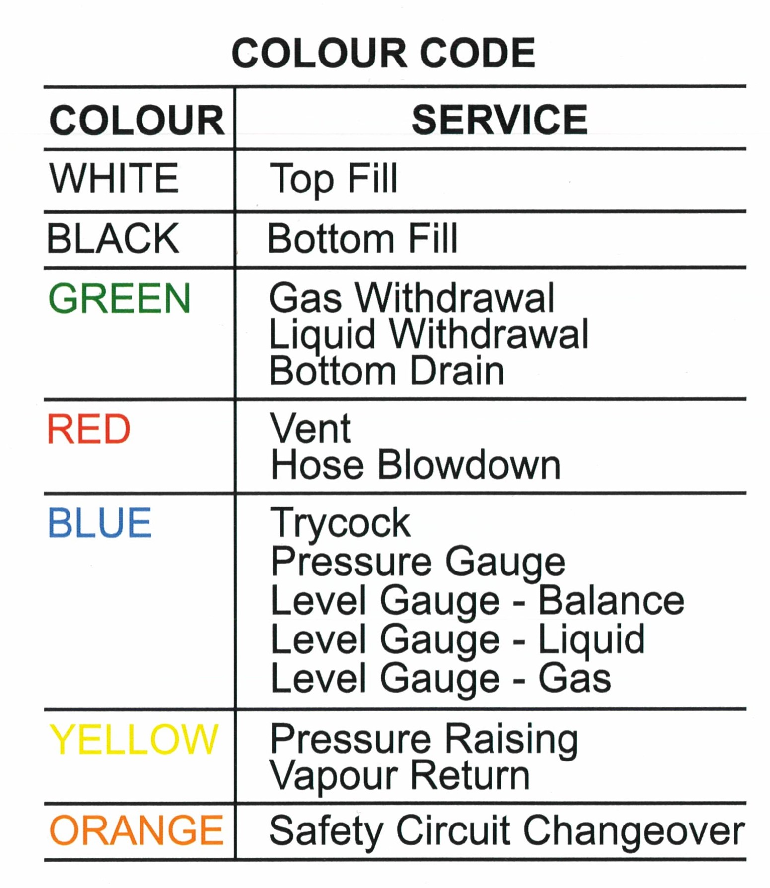
5.14 Valve HAND-WHEELS are COLOUR CODED correctly and in reasonable condition<br><br>- Paint if missing / repaint if faded or incorrect. <br>- Replace handwheels if they are damaged<br>- Refer to below chart for correct colours<br>
-
-
5.15 Pressure (and Contents) gauge is safety pattern type and is suitable for industrial gas service<br><br>Indications of compliance include:<br>- Has the words “Oxygen” and “Use no oil” or a pictogram of an Oil Can with an X through it.<br>- Has the words “Safety Pattern” printed on the face<br>- Indicates compliance with AS1349<br>- Indicates compliance with EN837-1 AND has X'd out Oil Can pictogram<br>- Blow out panel in rear of casing<br>- Blow out back<br>- Must not be clamped/bracketed across the back if this obstructs the blow out panel<br>- If in doubt, take detailed photos of all sides and printed information for review by TS Manager
-
5.16 Pressure gauge operates correctly<br><br>- Cross check reading with telemetry<br>- Check for needle movement when increasing/decreasing vessel pressure
-
5.17 Pressure gauge is marked with Working Pressure and Safety Valve Set Pressure<br><br>- Check that these match Actual Safety Valve set pressure and PB regulator set pressure
-
5.18 Contents gauge is marked with full and reorder points. <br><br>- Where possible, check that any Alarm contact switch is at the reorder point (eg. for Oxygen Vessels installed at Hospitals)<br>- Cross check against the contents chart for mmWC at Trycock<br>- Re-Order should be at 50% of Full (trycock)
-
5.19 Liquid relief valves are fitted everywhere required (anywhere liquid can be trapped between two valves) and are set at an appropriate pressure. - Set pressure must be appropriate for the line For reference: - Class 150 flanges (where fitted) - line relief valves set to 1,960 kPa or lower - Class 300 flanges (where fitted) - line relief valves set to 5,110 kPa or lower - Copper Type M: 1” dia. x 0.89mm wall thickness (WT) = 2,300 kPa (maximum) - Copper Type L: 1” dia. x 1.27mm (WT) = 3,400 kPa (maximum) - Copper Type K: 1”dia. x 1.65mm (WT) = 4,500 kPa (maximum) - Copper Type M: 1.5” dia. x 1.25mm (WT) = 2,280 kPa (maximum) - Copper Type L: 1.5” dia x 1.52mm (WT) = 2,800 kPa (maximum) - Copper Type K: 1.5” dia. x 1.83mm (WT) = 3,400 kPa (maximum) - S/S Tube & Pipe: For Cryogenic vessel systems = up to 5,000 kPa (nominally) - Check that line relief set pressures are higher than the vessel SV set pressure (to prevent unintended operation) - Check that line relief valves after the vaporiser are set at or below the vaporiser marked MAWP
- Yes - Fitted everywhere required and set correctly
- No - Fitted, but incorrect set pressure
- No - Not fitted everywhere necessary
-
Provide details of missing or incorrect line relief valves:
-
Provide detail of what is missing or incorrect:
6.0 GENERAL CONDITION INSPECTION ELEMENT
-
6.1 Vessel Paintwork condition<br><br>- Free from cracking, fading or chalkiness.<br>- Free of mould or algae growth<br>- "Poor" rating suggests repainting is required.
-
6.2 General cleanliness of the vessel surface and attachments<br><br>- Free from contamination on the vessel or in couplings and connections.<br>- Major cleaning is not required or recommended (consider whether cleaning would be practical and/or effective vs repainting)<br>- Perform spot or minor wash if required and practical.
-
6.2.1 Was the vessel cleaned in any way during this inspection visit ?
- Not at all
- Partially - nothing further required
- Partially - still needs further cleaning
-
6.3 Vessel LOGO is present and in good condition<br><br>- Note whether front and back logos are fitted.<br>- Note whether Logo is visible from any primary external viewing locations (eg. visible from nearest passing traffic or site entrance/access)
-
6.4 Vessel First Aid and Operating Instructions are present<br><br>- Refer to attachment below for correct details. <br>- Note that the last paragraph on the label must be removed or covered for medical or critical supply customers as it refers to isolation of supply (which should not be permitted in those cases).
-
-
6.5 Piping schematic is present, correct, and matches the actual piping configuration.
If not present, check that any proposed generic schematic label matches actual piping configuration before attaching. Otherwise, markup and forward to Tech Services at Yennora for action. -
6.5.1 Is a SCHEMATIC ATTACHED ?
-
6.5.2 Is the Schematic CORRECT and does it MATCH the AS_BUILT configuration (be aware of any post-installation additions/connections) ?
-
Please provide details of what is incorrect and needs to be updated. It is recommended to include some photos and a separate sketch if possible.
-
6.6 Is a CONTENTS CHART present and does it show the correct product ?
-
6.7 Valves TAGS are present and correct (ie. they match the schematic)<br><br>- Cross check against schematic. Replace as required.
-
6.8 Valves OPERATE properly and shut tight.<br><br>- Where possible, Test/check valves for smooth operation and tightness/leaks
-
6.9 Evacuation valve outlet is sealed/wired<br><br>- Take a photo of the evacuation connection to aid future maintenance preparation.
-
6.10 Filling coupling (incl. threads and seals) is in good condition
-
6.11 Coupling cap is fitted and appears to be regularly used
-
6.12 Pressure raising circuit is operating correctly.<br><br>- Where practical, verify correct operation by venting pressure and then checking for flow through PBC, and noting when flow stops & pressure stabilises.
-
Verified Set Pressure (kPa) =
-
Apparent Set Pressure (kPa) =
-
6.13 Top Fill and Bottom Fill isolation valves / Pressure Build isolation (Yellow hand wheel) were open upon arrival.
-
6.14 Ambient air vaporiser and pressure build coil are in good condition and not covered in excessive ice. Fan forced vaporiser (if installed) is operating correctly.<br><br>- Check for signs of damage, support cracking, foundation deterioration.<br>- Check all support brackets and bolts are secure
-
6.15 Telemetry unit is in an acceptable physical condition
-
6.16 Telemetry display is working and values are correct (the display updates when FILL button pressed).<br><br>- Cross check against analogue gauges (pressure and level) and Contents Chart
-
6.17 Confirm that there is no moisture inside the telemetry unit cover (external visual check only - do not remove cover unless necessary).
-
6.18 Conduit to telemetry unit and/or Level transmitter is free of cracks and in good condition.
-
6.19 Other Conduits and wiring are all in good condition.
-
6.21 Is a Down pressure regulator fitted to this vessel ?
-
6.21.1 Is the Down pressure regulator in good condition and operating correctly ?
-
6.21.2 Down pressure regulator operation:<br><br>- Where practical, test operation<br> - If the regulator is currently venting, vent vessel pressure further and note closure pressure<br> - If vessel pressure is lower than the down pressure reg. set pressure, increase vessel pressure (if practical) or remove and check function with cylinder gas source.<br>- Ensure it seals fully when pressure is reduced below setpoint
-
Verified Set pressure (kPa) =
-
Apparent Set Pressure (kPa) =
-
6.22 Task - Replace top and bottom fill valve seats
-
6.22.1 Valve brand
- Herose
- Mack Valves
- Bestobell
- Rego
- Johns
- Meca Inox
- Worcester
- Other (specify)
-
Specify Make:
-
6.23 Are the gaskets in the fill coupling flange and vapouriser connections correct?<br><br>- Gaskets approved for LOX service include Garlock Gylon 3505 (Blue)<br>- For all other services - Garlock Gylon 3502 (Fawn). Uniflon 51 or 53, Sigma 511 or 533.<br>- S/S Spiral wound gaskets are OK for inert service, but not for Oxygen<br>- White pure Teflon gaskets are not suitable<br>- Compressed Graphite gaskets are not suitable
-
If unsure, please describe the gasket (take photo if practical)
-
6.24 Check all valves and pipework for leaks with approved Leak Detection Fluid (LDF)<br><br>- Ensure lines being tested are under pressure - preferably normal vessel operating pressure<br>- Only compatible LDF is to be used and flushed with clean water after use<br>- Suitable products include:<br> • Snoop (Swagelok), VFV Leak Detector (Victoria Valves and Fittings), Sherlock Leak Detector, Big Blue Leak Detector
-
6.24.1 Has all Leak Detection Fluid been rinsed away with clean water ?
Details of any New/Replacements Parts Installed
-
Asset Number
-
Component
-
Existing Component Serial No.
-
New Component Serial No.
-
Reason for Change out
-
The inspection checklist is now complete. -
Has the vessel pressure been returned to normal operating conditions?
-
Vessel pressure before leaving site (kPa)
-
If vacuum pump down was completed, have you recorded the final vacuum reading at Q1.3.3 ?
-
Record progress vacuum reading (mTorr)
-
If there are any additional comments, please add them here :
Inspection Sign Off Clarification
-
The External Inspection Certification declaration on the following page relates ONLY to the fitness for service of the vessel itself and its integral attachments, and the safety valves as per AS3788 requirements.
It is a declaration that the vessel is SAFE to continue operation.
Minor defects or issues which do not compromise the ongoing safe or compliant use of the vessel, should not prevent the certification.
Issues which are not directly associated with the INTEGRITY of the vessel or safety valves, such as those associated with the installation (as per AS1894) should not prevent certification.
Therefore, Certification may still be issued, even if there are negative responses in the Inspection Checklist.
Negative responses in Section 3 (Safety Valve Visual Inspection) or Section 4 (External Vessel Visual Inspection) which directly affect safe operation, should be rectified before Certification is given, however, if they do not directly affect safe operation, then they should be marked for follow up action, and should not prevent Certification.
Any issues which in your opinion present an immediate and ongoing significant hazard, should be rectified immediately, and where warranted, the Technical Services Manager should be notified before leaving site. In extreme cases, and only in extreme cases, the vessel may need to be made safe and tagged out of service until the issues can be resolved.
If there is any doubt as to the safety or compliance of a vessel with regards to the statutory inspection elements for which you are providing certification, issues should be raised immediately with the Technical Services Manager for clarification.
External Inspection Certification - Pressure Vessel Fitness for Service
-
I the undersigned, certify that I have performed an external inspection, including a visual inspection of the safety devices, in accordance with AS/NZS 3788 and the attached checklist, on the Cryogenic storage vessel detailed in the attached report and as detailed below
-
Vessel Number
-
Vessel Manufacturer
- Armstrong Holland
- BTCE
- CEM
- Chart (China)
- Chart (USA)
- CIMC
- Cryeng
- Cryofab
- Cryolor
- Engineering Valves and Fittings
- Inox
- Johnson Engineering
- Linde
- Metro Engineering
- MVE
- Pioneer Cryogenics
- Taylor Wharton
- Toledo Engineering
- VRV
- Other
-
Specify Manufacturer:
-
Serial Number
-
MAWP
-
From the visual inspection undertaken, the vessel is
-
Not Fit For Continued Service for the following Reasons:
-
This Certificate shall, subject to the appropriate Regulations, remain in force for 4 years from the date of the inspection below. Any unauthorised or unexpected changes in the assessed conditions after this date, may render this certification invalid and subject to additional review.
-
Date:
-
Name & Signature:
-
GENERAL REQUIREMENTS
This Certificate is cancelled when the Vessel is sold or dismantled for erection on another site.
The Vessel is to be operated only while maintained in a safe condition with its fittings in correct adjustment and, where necessary by Certified Persons.
The Identification Number is to be kept clean and distinct.
Next Inspection Date is based on Table 4.1 AS/NZS 3788
