


Title Page
-
Document No.
-
Audit Title
-
Client / Site
-
Conducted on
-
Prepared by
-
Location
-
Personnel
Site Contact information:
-
Hospital Information
-
Hospital Name:
-
Hospital Address:
-
Hospital Address:
-
Vault/Bunker Reference:
-
Hospital contacts
-
Main hospital contact:
-
Building contractor:
-
Electrical contractor:
-
Radiation Protection Advisor:
-
Elekta contacts
-
Sales contact:
-
Site planning:
-
Project Manager:
-
Install IPLE:
-
Site FSE:
-
Supplier contacts
-
Delivery / Rigging:
-
Crane Certification:
-
RF Cage:
-
Philips:
-
Ferroguard:
-
Additional Information:
Site Survey #1
-
Date of Inspection:
-
Confirm site meets the minimum dimensions:
-
Length:
-
Width:
-
Height:
-
Confirm the B0 Survey test passed:
-
Feasibility layout agreed:
-
Delivery Route Agreed:
-
3D scan taken:
-
Additional Observations and Comments:
Site Survey #2
-
Have the permanent isocenter references been marked on the walls?
-
Is the certificate for the concrete specification available?
-
Note: To confirm the concrete is suitable – attach a copy of the concrete specification certificate with this report.
-
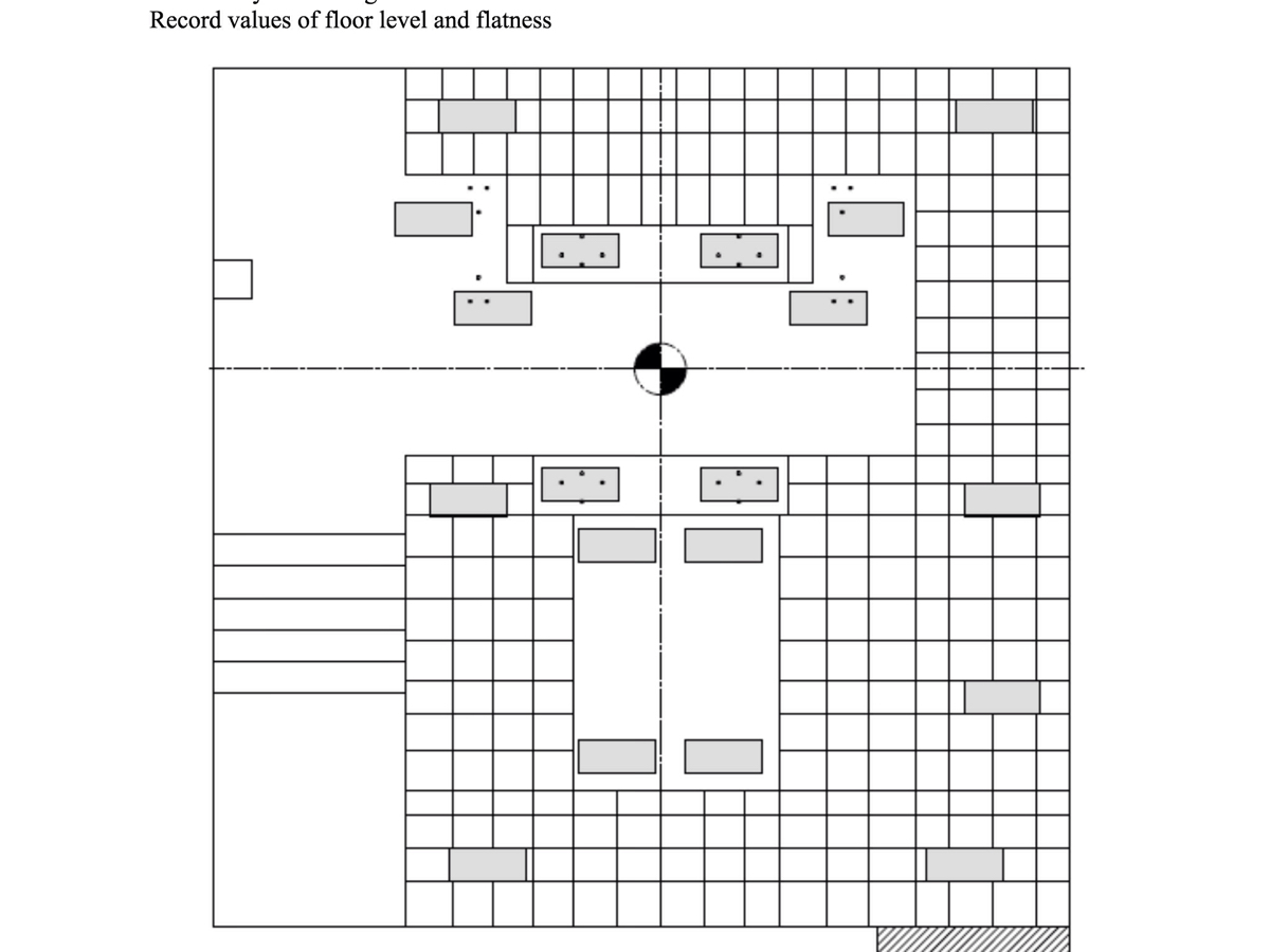
Confirm that the floor level and flatness is within the required tolerance.
-
To check the floor levels & flatness are as per the tolerances specified in drawing 1503509:
1. Position a 3 plane laser from the hospital finish floor level to isocenter.
2. Measure the floor heights of the treatment room floor, machine room/gantry pit and PSS pit, record the dimensions on sheet 6 of drawing 1503509 for each of the positions indicated.
3. To confirm that the floor level is within the required tolerance, move a 3 meter straight edge across the treatment room floor in all positions and orientations, looking for any deviations in the floor flatness.
4. When a deviation is visually identified, check the tolerance by trying to insert a 5mm shim in the gap seen. If the shim easily passes through the gap the deviation is above the required tolerance. This should be highlighted on the drawing by noting the deviation in the applicable location on the treatment room floor grid. -
1. Position a 3 plane laser from the hospital finish floor level to isocenter.
-
2. Measure the floor heights of the treatment room floor, machine room/gantry pit and PSS pit, record the dimensions on sheet 6 of drawing 1503509 for each of the positions indicated.
-
3. To confirm that the floor level is within the required tolerance, move a 3 meter straight edge across the treatment room floor in all positions and orientations, looking for any deviations in the floor flatness.
-
4. When a deviation is visually identified, check the tolerance by trying to insert a 5mm shim in the gap seen. If the shim easily passes through the gap the deviation is above the required tolerance. This should be highlighted on the drawing by noting the deviation in the applicable location on the treatment room floor grid.
-
Note: Record the values measured in the appendix drawing at the end of this check list.
-
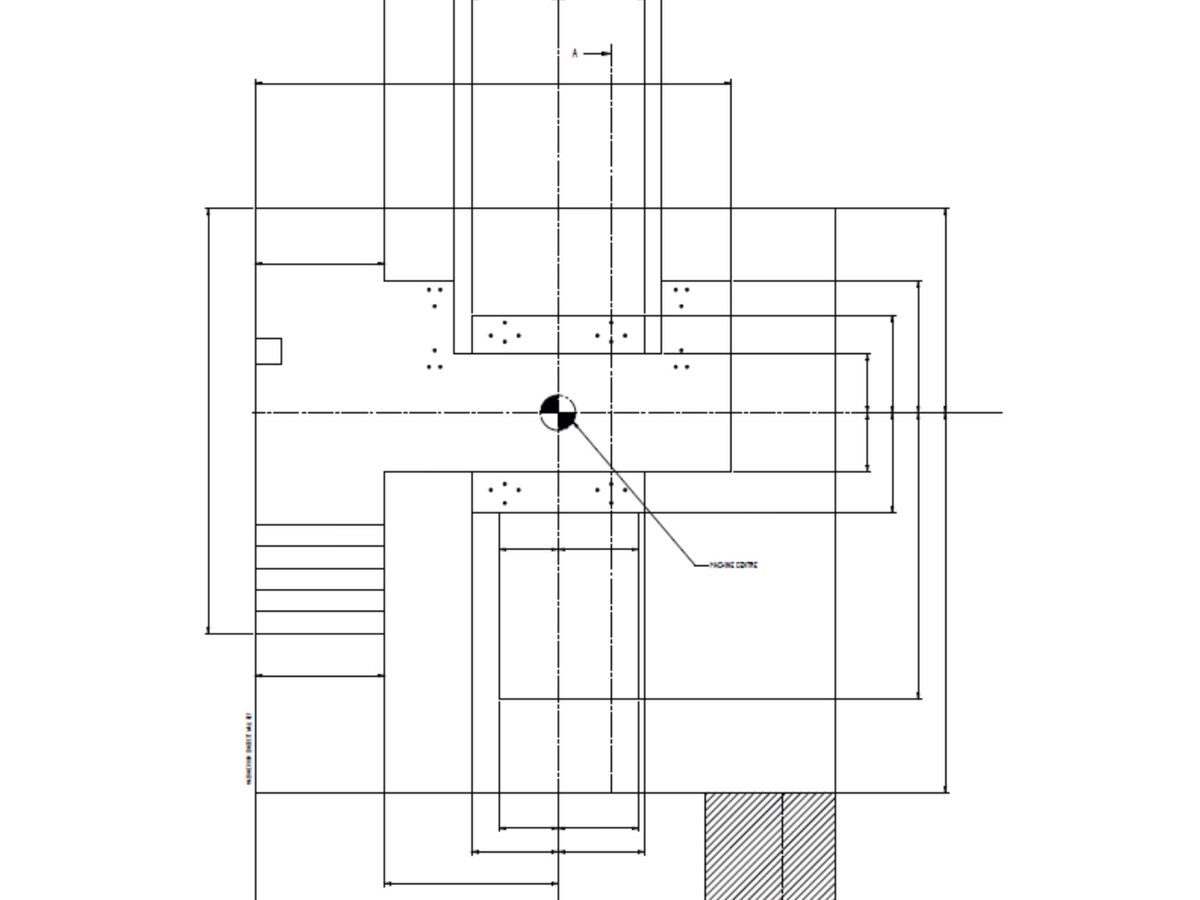
Confirm that the machine room, gantry & PSS pits are constructed within the required tolerance.<br> <br> <br> <br>
-
To check the machine room, gantry & PSS pits are as per the tolerances specified in drawing 1503509:
1. Position a 3 plane laser aligned to the hospital isocenter references.
2. Measure the room and pit dimensions and record the dimensions on sheet 6 of drawing 1503509 for each of the positions indicated and confirm that they are within the required tolerances and required minimum dimensions.
3. Confirm that the rear face of the gantry pit is parallel to isocenter by checking the maximum deviation between the back face of the pit and isocenter does not exceed the maximum allowed value
Note: Record the values measured in the appendix drawing at the end of this check list. -
1. Position a 3 plane laser aligned to the hospital isocenter references.
-
2. Measure the room and pit dimensions and record the dimensions on sheet 6 of drawing 1503509 for each of the positions indicated and confirm that they are within the required tolerances and required minimum dimensions.
-
3. Confirm that the rear face of the gantry pit is parallel to isocenter by checking the maximum deviation between the back face of the pit and isocenter does not exceed the maximum allowed value
-
Note: Record the values measured in the appendix drawing at the end of this check list.
-
Has the bunker burst panel been formed in the bunker (if required)?
-
Are the cable ducts complete between the technical room and the machine room?
-
Has the aperture for the Helium vent pipe been formed?
-
Radiation protection
-
Who is responsible for protection from radiation?
-
Have the drawings/plans been approved by the RPA?
-
Additional Observations and Comments:
Site Survey #3 - Access
-
Date of Inspection: (Site Survey #3)
-
Pre-installation notification
-
Delivery sequence and dates confirmed with customer?
-
Project plan up to date and circulated to all parties?
-
Delivery survey completed?
-
Delivery MSRA available & circulated to all parties?
-
Access for the gantry & magnet:
-
Is there a suitable off-loading area for fork lift/crane?
-
Is there an area allocated to park the delivery trucks?
-
Is the off-loading area the same height as the hospital?
-
Has there been provision to build a ramp or platform?
-
Confirm any required floor protection needed for manholes/ducts has been arranged.
-
What access is there into the treatment room
-
Roof : 2500 mm x 2700 mm minimum aperture
Or
Wall/direct door: 2500 mm x 2600 mm height -
Is there a minimum clear width of 2500 mm for the entire delivery route?
-
Is there a minimum clear height of 2600 mm for the entire delivery route?
-
Are all corners with the required specification for the turning circle?
-
Is the floor able to withstand a point load of 2750 kg?
-
Access for standard size components
-
Is this the same location and route as above?
-
If No answer the remaining question in this section
-
Is there a suitable off-loading area?
-
Is there an area allocated to park the delivery trucks?
-
Is the off-loading area the same height as the hospital?
-
Has there been provision to build a ramp or platform?
-
Has any required floor protection needed for manholes/ducts has been arranged.
-
Is there a minimum clear height of 2100 mm?
-
Is there a minimum clear width of 1200 mm?
-
General access to the treatment room
-
Is the route flat and free from any gradients on the route or in the treatment room?
-
Has suitable provision been made?
-
Has the rigging company arranged to fill the PSS pit with blocks and level to the treatment room floor ready for the delivery?
-
Has the rigging company arranged to cover the raised access floor with 12mm plywood panels or distributor plates to protect it for the installation of the gantry?
-
Has the access route been cleared of debris and swept clean?
-
Date agreed upon for this to be completed.
-
Is there a lockable storage area of approx.25m2 within close proximity?
-
Additional Observations and Comments:
Site Survey #3 - Treatment Room
-
Treatment Room Requirements
-
Are the air conditioning ducts available and ready to be connected to the plenums?
-
Are the flow and return correct to drawing 1514982 page 2?
-
Is there an air supply into the machine room?
-
Has the air conditioning ductwork been cleaned to remove dust?
-
Is the air conditioning functional and controlling the temperature to between 19°C to 22°C
-
Is the Helium Vent pipe in place, insulated and ready to be connected?
-
Has the date for the final Helium vent pipe connection been arranged and added to the project plan?
-
Are the chilled-water pipes for the Heat Exchanger in the correct position with Flow and Return labeled?
-
Do the chilled-water pipes have gauges and isolation valves above 3050mm, and are terminated at 2500mm with 32mm female BSP / NPT?
-
Is there water flow through the pipes ready for the installation?
-
Is there a pipe to connect the Heat Exchanger to the condensate drain?
-
Is the condensate pipe terminated with a ribbed hose tail suitable for a 12mm hose?
-
Is there a 12mm pipe ready to connect the SF6 filling station to the SF6 bottle, terminated with lossless couplings and with a valve that converts the pipe to 6mm?
-
Has the SF6 pipe work been pressure tested to 4bar?
-
Has there been provision made to bring medical gases into the machine room if required?
-
Are the fixings present for mounting the panel above the heat exchanger?
-
Is the required lighting in the machine room?
-
Is there 430mm of clearance before the crane location to allow the carriage to be installed?
-
Are the crane and raised access floor being mounted to a structural concrete wall or Has a suitable structure been designed that meets the specifications in drawing 1519759?
-
To confirm a structure is suitable measure the location of the fixing holes, and obtain documentation from a structural engineer to confirm the loading requirements.
-
Note: To confirm the crane mounting structure is suitable a copy of the structural design drawings should be attached with this report.
-
Is there temporary lighting in the treatment room?
-
Is there single phase power outlets in the machine room supplied with power?
-
Is the EPO switch installed in the machine room near to the location of the door?
-
Is the EPO switch wired to remove power from the Linac, MR and Services isolators?
-
Is the EPO switch functional and tested by the customer?
-
Are the Double pole isolators fitted on the machine room wall above the RF cage for the following supplies?
-
Lighting?<br> <br>
-
Emergency lighting? (optional)<br>
-
Mains sockets?<br>
-
Backed up mains? (optional)
-
EPO?
-
Is the treatment room door installed, with interlock switches wired back to the technical room ready to be connected to the CITB?
-
If the machine room door is to be constructed by the customer, is it installed, with interlock switches wired back to the technical room ready to be connected to the CITB or Has a date been agreed and added to the project plan for when this door needs to be constructed?
-
If required - is there a RADIATION ON warning light installed in the machine room, with wires back to the technical room ready to be connected to the CITB?
-
If required – has provision been made for the customer to provide RADIATION ON warning light(s) for the treatment room light, with wires back to the technical room ready to be connected to the CITB?
-
Is a fire detection system installed in the machine room?
-
Are provisions in place to install a fire detection system in the plenums/RF cage for the treatment room?
-
Note what type of fire detection is to be installed.
-
Does the bunker have a clear height of 3250mm to allow for the installation of the gantry and construction of the RF cage?
-
Are the bunker walls clear of switches, cable containment or other obstructions that might clash with the RF cage?
-
Are the cable trays / ladders present in the machine room to the location of the filter panels?
-
Has the area been cleared of debris and swept clean?
-
Has the floor been painted in accordance with the floor plan drawing 1503509 sheet 7 ?
-
Has the concrete been sealed to prevent dust?
-
Is the residual and surface moisture of the floor finish less than 3%?
-
Additional observations and comments:
Site Survey #3 - Control Room
-
-
Control room requirements
-
Is the control desk in position and finished?
-
Has the final floor been laid?
-
Has the ceiling grid and ceiling tiles been installed?
-
Does the control room have the required lighting?
-
Are the cable ducts installed between the control and the technical room, with draw-wires provided?
-
Are the cable trays under the control desk present and earthed?
-
If required – are there cable ducts between the control room and machine room?
-
Is the air conditioning system functional and tested?
-
Has the air conditioning ducting been cleaned to remove dust?
-
Are the single phase power outlets installed and supplied with power?
-
Is there an EPO switch in the control room?
-
Is the EPO switch functional and tested by the customer?
-
Is there a 13amp supply available for the Ferroguard control unit?
-
Is there cable containment available between the Ferroguard control unit and the location for the sensors?
-
Is there 2 meter or less between the positions for the Ferroguard sensors?
-
If required - is there a radiation warning light installed with wires back to the technical room ready to be connected to the CITB?
-
Is the fire detection system installed in the control room?
-
Has the control area been cleared of debris and swept clean?
-
Date agreed upon that this will be completed.
-
Additional observations and comments:
Site Survey #3 - Technical Room
-
Technical room requirements
-
Has the final floor been laid?
-
If required - has the ceiling grid and ceiling tiles been installed?
-
Does the technical room have the required lighting?<br>
-
Are the cable trays present and earthed?
-
Is the air conditioning system functional and tested?
-
Has the air conditioning ductwork been cleaned to remove dust?
-
Are the chilled-water pipes for the LCC in position labeled with Flow and Return?
-
Do the chilled-water pipes have gages, isolation valves and are terminated above 2350mm with:<br>- 1 x 32mm BSP threaded flat seal male<br>- 1 x 32mm BSP threaded flat seal female
-
Is there water flow available through the pipes ready for the installation?
-
If required is there a backup water supply available?
-
Are there single phase power outlets installed and supplied with power?
-
Is the 3 phase isolator present for the treatment delivery system supply?
-
Is the 3 phase isolator present for the MR supply?
-
Is the 3 phase isolator present for the service supply?
-
Is there an EPO switch in the technical room?
-
Is the EPO switch functional and tested by the customer?
-
Is there a network connection available to the hospital network?
-
Is a fire detection system installed in the technical room?
-
Has a location been identified to secure the SF6 bottle with the SF6 pipe in position?
-
Is SF6 available in a small bottle?
-
Is the double stage 0-5 bar SF6 Regulator available?
-
Has the Technical room been cleared of debris and swept clean?
-
Date agreed upon that this will be completed.
-
Additional observations and comments:
Site Readiness Confirmation
-
Date of Confirmation:
-
Site is ready for the installation?<br>
-
Signature
-
Name & position of Signature:
Appendix -1
-
Site Survey 2 Drawings
Record values of floor level and flatness -
Record values of floor level and flatness.
-
Record values of the machine room, gantry & PSS pit dimensions
Site Pictures
-
Site Pictures:


