


Title Page
-
Business Name
-
Location
-
Date of Inspection
-
Inspector
Plans / Drawings
-
The approved plans / drawings are on-site or are available to the contractor.
Visual Inspection
-
Piping, joints, and valves are uncovered.
-
Mains that supply the fire hydrant(s) are a minimum of 6" nominal size.
-
Is a meter installed in the supply line to the fire hydrant?
-
Is the meter listed for fire protection service?
-
Is a backflow prevention device installed in the supply line to the fire hydrant?
-
Is the backflow prevention device listed for fire protection service?
-
Is a check valve or alarm check valve installed in lieu of a backflow prevention device?
-
Is the check valve or alarm check valve listed for fire protection service?
-
A control valve is installed within 20 feet of each hydrant.
-
The control valve for the fire hydrant is a listed indicating valve; or a listed, non-indicating valve (underground gate valve) installed in a roadway box.
-
No check valves, detector check valves, backflow prevention valves, or other similar appurtenances are installed between the fire hydrant and the control valve for that hydrant.
-
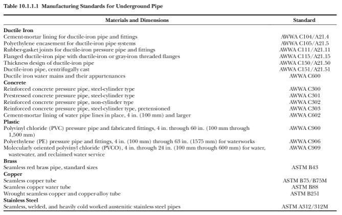
Piping is manufactured in accordance with NFPA 24, Table 10.1.1.1 (Manufacturing Standards for Underground Pipe).
-
Table 10.1.1.1 Manufacturing Standards for Underground Pipe
-
Piping is rated for the maximum system working pressure to which the piping will be exposed (not rated less than 150 psi).
-
Depth of piping is sufficient for protection from freeze and mechanical damage.
-
Depth of Piping (minimum 30" from top of the pipe to final grade; minimum of 36" under driveways/roads; minimum of 4' below railroad tracks or under large piles of heavy commodities or subject to heavy shock and vibrations).
-
Direction changes and thrust blocks or restrained joint systems match approved plans.
-
Corrosion resistance, such as coating and wrapping, is installed where necessary.
-
The tightness of bolted joints is verified by bolt torque or other methods approved by the manufacturer.
-
All bolted joint accessories are cleaned and thoroughly coated with asphalt or other corrosion retarding material after installation.
-
Where metal pipes of dissimilar metals are joined, they shall be insulated against the passage of an electric current using an approved method.
-
Bedding and backfill material on-site match the approved plans, do not exceed 3/4" particle size, and contain no ashes, cinders, refuse, organic matter, or other corrosive materials.
-
Backfill material is tamped in layers or in puddles under and around pipes to prevent settlement or lateral movement.
-
The hydrant on-site is listed and approved (matches approved plans).
-
Hydrant is installed on flat stone, concrete slab, or other approved materials.
-
Small stones or an approved equivalent are provided below and around the drain in an adequate amount to prevent the weep hole from being clogged with soil, mud, or debris.
-
The center of all hose outlets are located between 18 and 36 inches above final grade.
Hydrostatic Test
-
Trench is backfilled between joints.
-
The gauge is located at the lowest elevation or portion of the system being tested.
-
Starting pressure is minimum of 200 psi or 50 psi in excess of the system working pressure, whichever is greater.
-
Pressure pumps disconnected after initial pressurization.
-
The test lasted a minimum of two (2) hours; resulting in less than five (5) psi of pressure loss.
-
The pressure was relieved from the system and the gauge returned to zero (0) psi.
Line Flush
-
Flow through a minimum of 4" hose or pipe.
-
Hose or pipe is restrained prior to flowing water.
-
Observe flush or swab until clear of all debris.
Final Acceptance
-
Control valves are clearly identified and free of obstructions.
-
Physical impact protection is provided around hydrants susceptible to vehicular impact.
-
Operational test of control valves under normal system pressure (does not close in less than 5 seconds when operated at maximum possible speed from the fully open position).
-
Operational test of fire hydrant under normal system pressure.
-
Fire hydrant properly drains after operation.
Documentation
-
Contractor's material and test certificate(s) are received.
-
https://www.tdi.texas.gov/forms/sfmfireindustry/sf042sprundergd.pdf
Inspection Status
-
Inspection Status
-
Next Inspection
-
Owner / Representative
-
Phone #
-
Email Address


")