


Title Page
-
Site conducted
-
If package contents are missing or have been damaged please contact 24/7 Support Center for further details
-
This document must be lodged with 24/7 Support Center, please reply to the email received from Support upon registration of this system, and attach a scan of this page
-
Client Name:
-
Conducted on
-
Prepared by
- Joe
- Matt
- Fred
-
Location
-
Job Card Number (Ticket Number):
-
Vehicle Fleet ID
-
Photo of Vehicle Fleet ID
-
Vehicle Registration
-
Photo of Vehicle Registration
Vehicle Details
-
Vehicle Make
-
Vehicle Model
-
Year
-
ODO
Guardian Installation Checklist
-
Pre Install Photos Completed
-
Guardian Live Fleet Name:
-
Guardian Controller Serial Number*
-
Photo of Guardian Controller Serial Number*
-
3G Provider
-
3G Number
-
3G APN
-
IPV6 Address (If IPV4 is changed)
-
SIM Serial Number
-
Photo of SIM Serial Number
-
Camera Pitch Setting
-
Camera PitchTo top
-
The Pitch is the angle of up and down movement, when the driver is looking straight ahead they are at a Pitch of zero (0), if the In-Cab Sensor is mounted on the top of the dashboard the Pitch angle is usually 10, this is measured by using a protractor from the driver’s eyes at the zero position and measuring the angle of where the ICS is, which is 10 degrees down
-
The ICS must always be mounted below the drivers line of sight, and the change in angle is usually 5 degrees of change
-
Camera Yaw Setting
-
The Yaw is the angle of left and right movement, when the driver is looking straight ahead they are at a Yaw of zero (0), if the In-Cab Sensor is mounted on the left edge of the steering wheel, the Yaw angle is approximately -20 degrees, and if its mounted to the right edge of the steering wheel the Yaw is approximately 20 degrees, this is measured by using a protractor from the driver’s eyes at the zero position and measuring the angle of where the ICS is
-
The change in angle is usually 5 degrees of change
-
Photo of Camera
-
Photo of Controller Mounting
-
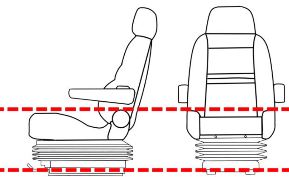
How has the Vibration Motor been mounted?
-
If the motor is outside the area of the two lines you will need to tell this to 24/7 Support Center upon
registration of the vehicle. -
Photo Of Vibration Motor
-
Photo of Wiring connections
-
Photo of GSM antenna
-
Photo of GPS antenna
-
Has a Cruise Control Bypass been fitted
-
Cruise control Bypass Photo
-
Has The Vehicle Been Isolated?
Sign Off
-
Photo of diagnostics page
-
Photo of Camera vision on diagnostics
-
Confirmed Working On Guardian Live with
-
Test Events Received
-
Installer Sign Off: - As a certified installer for Seeing Machines, I agree I have completed the install as per my training
-
Client Sign Off: - As the representative for my company I agree the installation has been installed correctly
")
