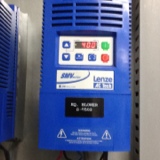
Information
-
Document No.
-
Audit Title
-
Client / Site
-
Conducted on
-
Prepared by
-
Location
-
Personnel
Installation
-
Incoming power connected to L1, L2 and Lq3 for 3 phase and L1 and L2 for single phase
-
Note. These are on the opposite side then the automation drives
-
Motor leads connected U11, V12 and W13
-
Run relay between 1 and 4
-
Analog in between 25 and 2 for 4-20 ma or 5 and 2 for 0-10 Vdc
-
Analog out from 30 and 2. 0-10 Vdc
-
Alarm contacts connected set with parameter P140
Parameter setup
-
P100. Start control source. Set to 1
-
0 - local keypad. 1 - Terminal strip. 2 - Remote keypad. 3 - Network. 4 - Terminal strip or local keypad. 5 - Terminal strip or remote keypad 6 - CTRL button
-
P101 reference source Set to 0
-
0 - Keypad 1 - 0-10 Vdc 2 - 4-20 ma 3 - Preset #1 4 - Preset #2 5 - Preset #3 6 - Network
-
P102. Minimum frequency. Set to 30
-
P103. Maximum frequency Set to 60
-
P104. Acceleration time. Set to 10<br><br>
-
P105. Deceleration time. Set to 10
-
P107. Line voltage Set to 1<br>
-
0 - Low 120, 200, 400. 480 vac 1 - High 120, 240, 480, 600 vac
-
P108 motor overload. Set to 100%
-
P110. Start method. Set to 3
-
0 - normal 1 - Start on power up 2 - Start with DC brake first 3 - Auto restart 4 - Auto restart with dc brake first 5 - Flying restart 6 - Flying restart with restart #2
-
P111. Stop methods. Set to 0
-
0 - Coast 1 - Coast with dc brake 2 - Ramp 3 - Ramp with dc brake
-
P112 Rotation. Set to 0
-
0 - Forward only 1 - Forward and reverse
-
P121 TB-13a input function. Set to 20 to reset fault
-
P140. Relay output Set to 3 for fault output
-
P150. TB-30 analog output. Set to 4 for 2-10 Vdc proportional to load<br>
-
P153. Analog out scaling Set to 200%
Motor setup
-
P300. Drive mode Set to 1
-
0 - constant v/Hz 1 - Variable v/Hz 2 - Enhanced constant V/Hz 3 - Enhanced variable V/Hz 4 - Vector sped 5 - Vector torque
-
P302. Motor voltage. Set to 575
-
P303 Motor current. Set to motor current
-
P305. Motor RPM. Set to 1750


