


Information
-
Document No.
-
Audit Title
-
Client / Site
-
Conducted on
-
Prepared by
-
Location
-
Personnel
-
Select date
-
Add location
Collection and organization of materials
-
Have All materials been collected and organized to assemble the system?
-
Please photograph assembled hardware for installation
-
Powercon cables
-
Rigging hardware
-
Safety cables
-
Pins
-
Rigging plates
-
Array frame
-
Array elements
-
Audio cables
-
If any equipment appears damaged please document here
Testing of array components to validate proper operation
-
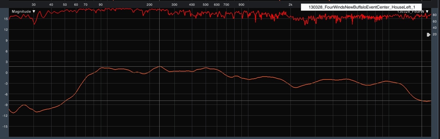
Prior to assembly of the system, array elements must be tested to ensure proper operation as well as consistency between elements. This will be accomplished utilizing the dual channel transfer function measurement system (SMAART or equivalent system. Complete the following tests to ensure proper operation of each element.
-
Use the transfer function settings shown here when taking measurements
-
Find a quiet space, preferably outdoors in a parking lot, or other large open area away from walls. Place the array element on the ground and place your measurement microphone on the ground directly on access to the element 1 meter away.
-
Capture and save the transfer function measurement of each array element. When saving traces please use the example below to name traces so they can be easily recalled in the future if needed.
The naming convention follows this basic format
Date: year, month, day
Venue: Venue location and room information
Array position: numbering begins at the top of the array.
130228_FourWindsNewBuffaloEventCenter_HouseLeft_1 -
Once all measurements are captured, compare each trace and note any analogies, or any difference between elements that is greater than 1dBFS.
-
If any anomalies or significant differences between elements are found, please indicate the areas that are problematic and document here.

Array assembly and rigging.
-
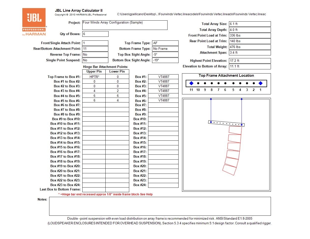
The array should be assembled as shown in the prediction software. All angles must be exact and the overall angle of the array should be set with a inclinometer. See the configuration below for details on all angles, connection points, weight elevation, etc.
-
Begin assembling the array with the array frame on the ground. Attach the first element of the array using the correct splay angle as shown in the array prediction.
-
Once the first element is hung, slowly raise the array and connect the second element with the correct splay angle as shown in the prediction. Continue this process for all elements of the array. While connecting elements of the array, connect and properly dress power, audio and safety cables as required.
-
Ensure that all connecting pins are fully seated and locked in place, then double check that all pins are fully seated and locked in place.
-
Once all elements are hung and properly connected, document the result with photographs from the front, back left and right of the array.
-
Raise the array to the desired height shown in the prediction.
-
Adjust overall vertical angle of the array to the specified angle using your inclinometer.
-
Adjust the horizontal orientation of the array as specified.
-
Photograph the final result.

")
 - duplicate")
