 - duplicate")


Title Page
-
Site conducted
-
Project: Hollandse Kust Zuid
Task Plan: NS2244-ENG-00024-ATT01
Procedure: NS2244-ENG-00024 Cable Termination Power Cores FOU
Rev: 1 -
Conducted on
-
Location ID
-
Cable type
-
String
-
Foundation
-
Cable ID
-
Prepared by
General Info and Task Objectives
-
Task Summary
1) Inner-array power cores termination onto WTG foundation switchgear
2) Completion of power cores cleating
Sub Task # 1) Preparation
-
Are you performing this Sub-Task?
-
1.1 Perform Introduction and Toolbox talk with all involved personnel
-
Check for a valid permit and review required safety measures.
-
1.2 Perform Radio communication check with ISV
-
1.3 Lift tools from ISV to EWP.
-
1.4 Verify your location, the cable ID, cable route and switchgear location<br>and ID.
-
1.5 Ensure that the cable and switchgear are disconnected from any<br>voltage source and are earthed.
-
Check for a valid E-Permit with isolation measures detailed.
-
1.6 Check that all termination kits are provided and are suitable for the<br>installation (matching the cable size).<br>Check that all tools required for the work is available and in good<br>condition.
-
1.7 Ensure all sharp edges are covered with rubber or foam to prevent<br>damages to the cable. (i.e. switchgear platform opened hatches edges).
-
1.8 Check the accessible sections of the subsea power cores for outer sheath<br>damages visually and with pulling the hands over the surface. Any<br>repairs necessary shall be performed before termination.
-
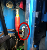
1.9 Cover the cable compartment door mechanism with<br>(plastic cylinder shape).
-
-
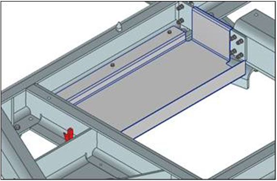
1.10 Install the temporary termination platform that will be used by the jointers in front of the GIS.
-


Sub Task # 2) Termination (TKF Cable)
-
Are you performing this Sub-Task?
-
2.1 Assemble the TE Screened Separable Connector 1250 A onto the TKF Cable according to T-connector 500/800 mm2 installation manual, Document Number: 34032-IIN-OF0260994.
-
2.2 Each step of the Installation Manual has been extracted and inserted below, should there be any discrepancies the contents of the Manufacturers Installation Instructions shall prevail.
-
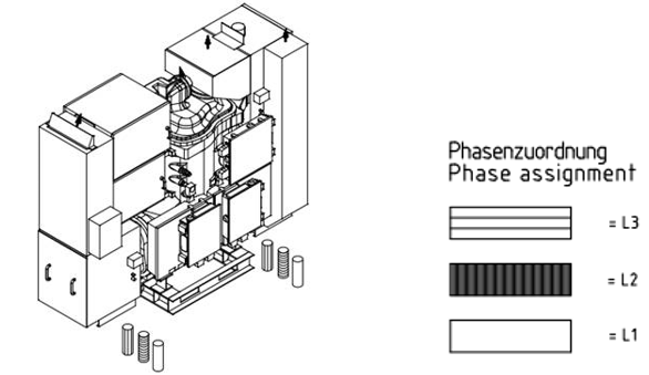
2.3 Confirm the correct phase order, which is for every cable in the switchgears left-to-right L1, L2 and L3
-
-
2.4 General Instructions – Before Starting:
• Check the kit label and the title of the installation instruction to prove that the cable accessory you are going to use matches the cable.
• Make sure the cable is properly sealed.
• Make sure the cable is in the final installation position.
• Check the position of the cables to be in alignment to the final position of the accessories.
• Make sure the joint bay/installation area provides adequate space for the cable components to be parked on either cable for later use during the installation.
• The joint bay/Installation area must be kept clean and dry during installation. For outdoor installation use tent or other appropriate shelter.
• Carefully read and follow the steps in the installation instructions. Components or working steps may have been changed/improved since you last installed this product.
• All tools, PPE and apparatus used must be kept clean during the installation.
• Obey relevant and local security and safety rules during the installation. -
2.5 Shrinking Heat-Shrink Tubing:
• Use a propane (preferred) or butane gas torch.
• Ensure the torch is always used in a well-ventilated environment.
• Adjust the torch to obtain a soft blue flame with a yellow tip. Pencil-like blue flames should be avoided.
• Keep the torch aimed in the shrink direction to preheat the material.
• Keep the flame moving continuously to avoid scorching the material.
• Clean and degrease all parts that will come into contact with adhesives.
• If a solvent is used follow the manufacturer’s handling instructions.
• Start shrinking the tubing at the position recommended in the instructions.
• Ensure that the tubing is shrunk smoothly all around before continuing along the cable.
• Tubing should be smooth and wrinkle free with inner components clearly defined. -
2.6 Stripping the Cable:
Use appropriate stripping tools for smooth and even insulation diameter.
Adjust the stripping tool to the thickness of the semi-conductive layer. Avoid removing too much of the insulation. Polish the stripped surface by hand using the supplied abrasive paper beginning with the lowest grid size, or by an appropriate sanding machine and abrasive paper and grades. The surface of the insulation must be even and free of all traces of conductive material. -
2.8 RSTF Tool Checklist: In order to install RSTF base and coupling connectors, the following tools are required:
• Heating device and slide rails (for cable straightening).
• Heat gun or torch (for cables with Aluminum laminated sheath only).
• Ligarex pliers (for cables with Aluminum laminated sheath only / TE Connectivity ordering reference IT-1000-004).
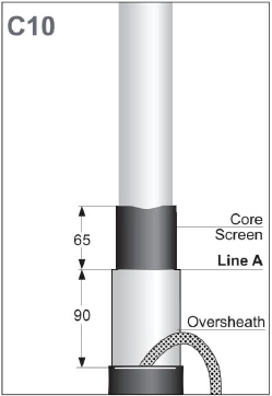
• Suitable cable screen removal tool that can remove screen down to a distance of 65 mm from the oversheath.
• Suitable cable Insulation removal tool
• Torque wrench.
• 8 mm socket (for cables with metal tape/foil shield only).
• 10 mm socket (for cables with Cu-wire shield only).
• 13 mm socket.
• 24 mm socket.
• 24 mm deep socket (for coupling connector installations only).
• 8 mm Allen bit (for base connector installations only).
• 17 mm Allen bit (for coupling connector installations only) -
2.9 Straightening and Heating of the Cable.
-
2.10 Before starting the cable preparation, train the cable end in the straight installation position and fix it.
-
2.11 The cable needs to be heated and straightened for the length of complete Installation.
-
2.12 In case of graphite coating cover the cable with one layer of crepe paper.
-
2.13 Degrease and clean the over sheath.
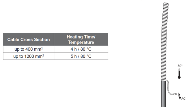
-
2.14 Heat the cable by applying a heating device to the over sheath as shown in the TABLE BELOW
-
-
2.15 Before stripping to the required dimensions, the cable needs to be cooled down to ambient temperature using slide rails.
-
-
2.16 Marking Reference Lines
-
2.17 For switchgear connectors: Before starting, place cable cabinet grommets.
-
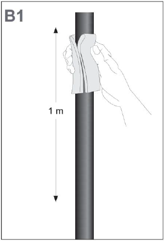
2.18 Clean and degrease the over sheath with solvent wipe over a length of 1m from the center of the bushing.
-
-
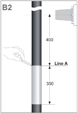
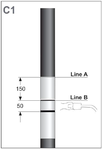
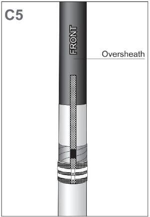
2.19 Position the cable with sufficient overlap to the bushing center.<br><br>Mark the cable core at distance 400 mm below the bushing center (Line A)<br><br>Remove the outer semiconductive screen from the outer sheath 350mm down from Line A.<br>
-
-
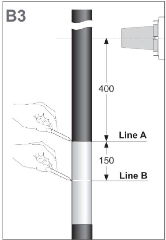
2.20 Make sure the Line A is still visible 400mm below the bushing center<br><br>Mark the core a second time (Line B) 150mm below that<br>
-
-
2.21 Mark a 50mm long over sheath segment below Line B <br><br>Heat the 50mm wide segment with a propane flame until soft.
-
-
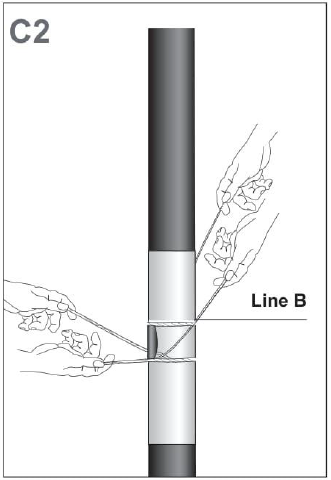
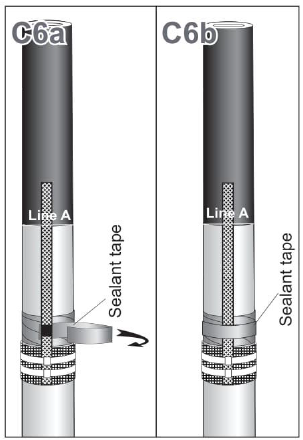
2.22 With the yellow aramid string, cut through the over sheath.<br><br>Remove the marked over sheath segment from the Al-laminated foil by slicing it away bit by bit with the string as shown in the drawing.<br>
-
-
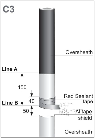
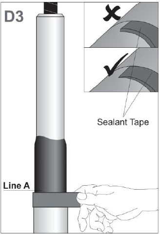
2.23 Clean the AL tape from traces of the outer jacket (if any).<br><br>Degrease, clean and abrade with sandpaper the over sheath for about 100mm, above and under the removed over sheath.<br><br>Wrap 1 strip of sealant tape (red) with a small overlap and slight tension around the end of the over sheath for a length of 40mm.
-
-
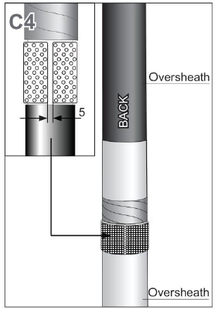
2.24 Measure the circumference over the Al tape and cut the contact plate 5mm shorter than the measured length (if the contact plate is shorter do not cut).<br><br>Bend the contact plate and position it tight over the aluminum tape. Make sure that to open end of contact plate is positioned to the back side of the cable.
-
-
2.25 On the front, place the earth lead over the cable. Make sure that the moisture block of the earth lead is positioned in the middle of the red mastic. The braid must leave from the top direction.<br> <br>Fix the earth lead onto the contact plate using 2 Ligarex tie wraps (using special Ligarex pliers – TE Connectivity ordering reference IT-1000-004).<br> <br>Cut the excessive earth lead. Fix the braid up temporarily while the preparation is done.<br>
-
-
2.26 a. Lift up the earth lead and wrap 2 layers of red sealant tape without applying tension around the moisture block.<br> <br>b. Press the moisture block covered with mastic against the over sheath and wrap a strip of red sealant tape around both cable and moisture block.
-
-
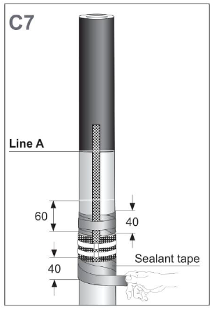
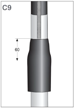
2.27 Wrap 1 turn of sealant tape (red) with a small overlap and slight tension around the over sheath (under the removed over sheath) for a length of 40mm<br> <br>Mark the cable at 60mm above the removed over sheath.
-
-
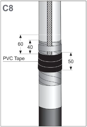
2.28 Apply 5 layers of PVC tape to cover the contact plate area of 50mm as shown, make sure no sharp edges are remaining.
-
-
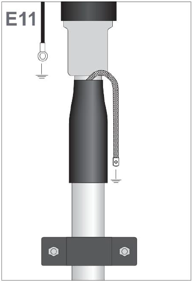
2.29 Position the heat shrink sealing over the earth connection. Align the top of the sealing sleeve with the mark placed in step 2.27 (covering 60mm of the upper over sheath) and start heating from the top working downwards.<br> <br>Fix the earth lead onto the over sheath with a wire binder just above the sealing sleeve. Bend down the braid and flatten over the cable.
-
-
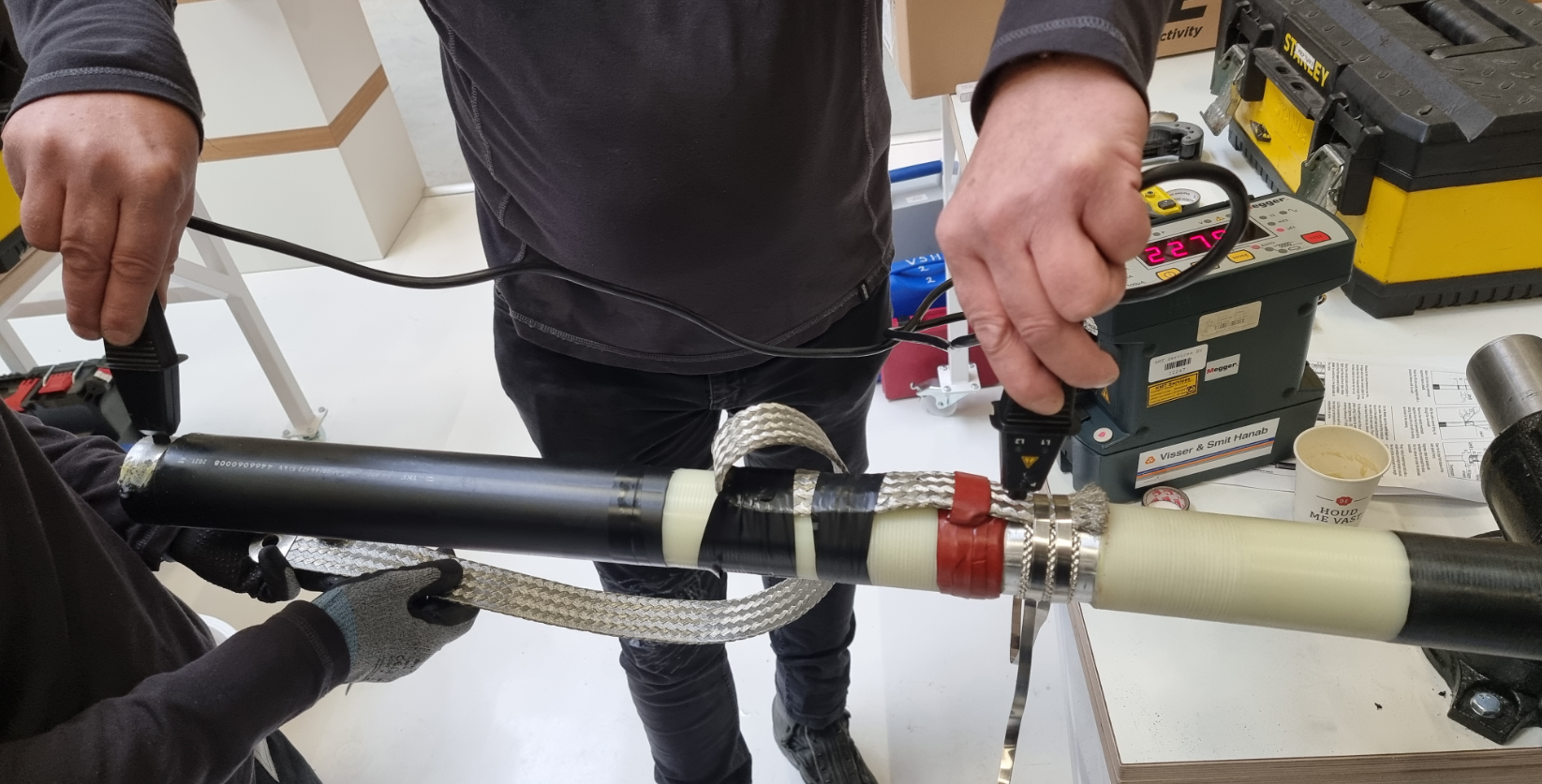
2.30 The contact resistance of the connection between the cable screen and the earthing braid shall be measured using a calibrated digital micro-ohmmeter.
-
2.31 Carry out a contact resistance check of the earthing connections and record the results
-
-
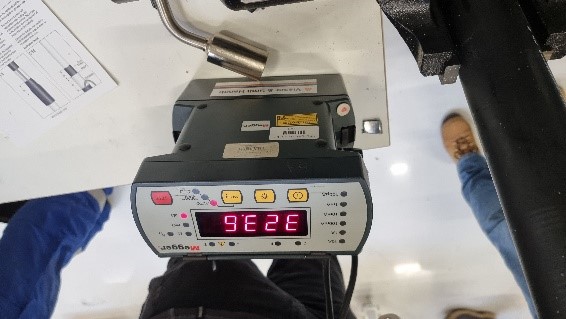
2.32 Photograph including date/time stamp shall be taken showing digital readout on the CR Test Unit.
-
-
2.33 Acceptance criteria shall be: ≤0.5mΩ
-
2.34 Remove the over sheath and the Alu-foil over the complete length above Line A.<br> <br>Remove the core screen with appropriate screen cutting tool according to the drawing. The surface of the insulation should be free from all traces of conductive material.<br> <br>Compare the diameter over insulation with the application range as shown on the supplied stress cone.<br> <br>Application Check!
-
-
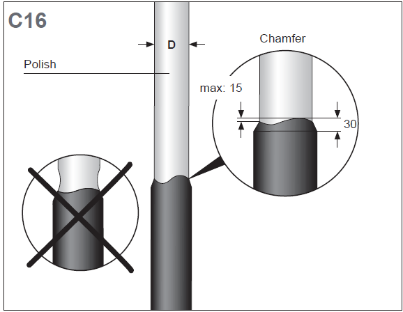
2.35 Chamfer the insulation screen<br> <br>Abrade and smooth the insulation from the screen cut towards the end.<br> <br>Do not nick the insulation.<br><br>Make sure the semicon transition wave shape is in accordance with the values shown in the drawing. Clean and degrease the insulation with the supplied cleanser in direction of the semicon to prevent contamination. Take care to ensure that the diameter of the insulation is not reduced close to the transition to the semiconducting layer. <br><br>Check dimension D. The finally prepared diameter over insulation shall be within the application range of the stress cone, marked at the rubber body.
-
-
2.36 Photograph including date/time stamp shall be taken showing the prepared power core.
-
2.36 Insulation Cut-back and Pre-installation
-
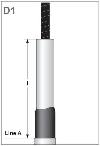
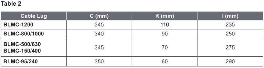
2.38 Cut back the insulation according to the dimension I (see table 2).<br> <br>For TKF cables 304520 and 304802: It’s not needed to remove water blocking compound<br> <br>For cables with longitudinal water blocking material from other manufacturers: Refer to the appropriate jointing instructions.<br> <br>Protect the end of the conductor with several layers of PVC tape.
-
-
-
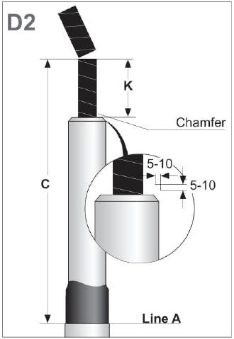
2.40 Chamfer the edge of the core insulation with appropriate tool to facilitate pushing on the stress cone adapter.<br> <br>Protect and cut the conductor on the length K (see table 2), verify the length C (see table 2).<br> <br>Remove any sharp edges and thoroughly clean the insulation and core screen.
-
-
2.41 Apply one sealant tape (grey) with slight tension and its top edge aligned with Line A on the end of the outer sheath.<br> <br>Flatten the ends of the sealant tape and push them together to avoid air gaps.
-
-
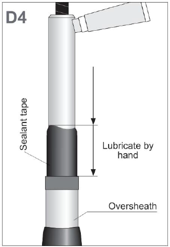
2.42 Gently lubricate the outer surface of the core insulation, semiconductive insulation screen and sealing tape with a thin layer of assembly lubricant.<br> <br>Apply the lubricant layer with the sponge top (on cable insulation) and hand (on semiconductive screen and sealing tape) as shown.
-
-
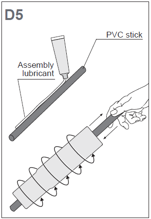
2.43 Clean the PVC stick and apply assembly lubricant as shown.<br> <br>Slide the PVC stick into the stress cone and turn the stress cone adapter to fully cover the inner surface of the stress cone adapter with lubricant.<br>
-
-
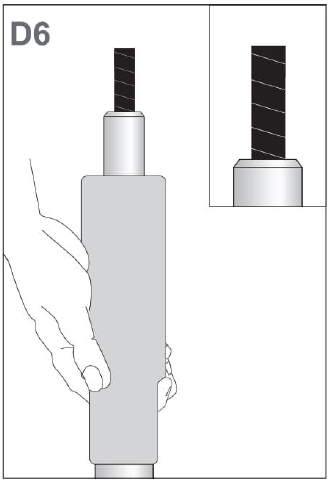
2.44 Push the stress cone in one sequence with a twisting movement onto the insulation until the inner collar of the stress cone stops at the over sheath.<br> <br>Afterwards, remove the PVC protection wrap from the conductor. Remove excess grease and clean.
-
-
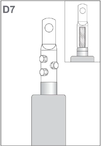
2.45 Position the cable lug on the conductor so that the end of the conductor touches the end of the lug’s barrel. Align the palm hole with the thread in the bushing.<br> <br>Install the cable lug using a lug fixture. Tighten the set of bolts gradually in several equal steps starting at the bolts closest to the insulation cut. Continue until the heads shear off.<br> <br>Remove any sharp edges.
-
-
2.46 Photograph including date/time stamp shall be taken showing the Insulation Cut-back and Pre-installation.
-
2.47 Installation of Base Connector (Use the box Final assembly)
-
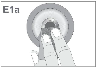
2.48 Abrade and clean the contact ring of the bushing thread from residuals such as resin or varnish if any.
-
-
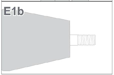
2.49 Insert the threaded pin into the bushing and tighten it up with an Allen key (8 mm). Maximum torque as per Switchgear manufacturer. 8VM1 Siemens: 70Nm If not specified, Maximum Torque is 80 Nm
-
-
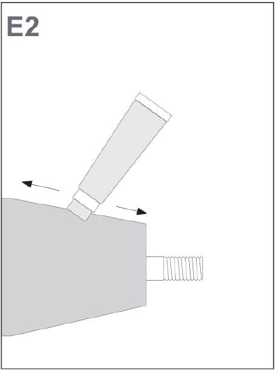
2.50 Clean the conical surface of the bushing and lubricate it with the assembly lubricant as shown.
-
-
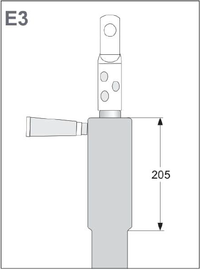
2.51 Clean the surface of stress cone and apply a thin layer of lubricant onto the outer surface over a length of 205 mm with the sponge top as shown in the drawing.
-
-
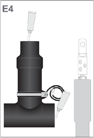
2.52 Clean and degrease the bottom and front end of the screened connector body and apply a thin layer of lubricant onto the inner surface without the sponge top as shown.<br> <br>Use one way glove and PVC stick to evenly lubricate the entire inner surface.
-
-
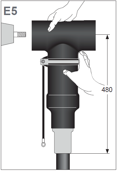
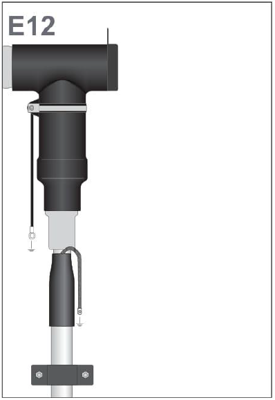
2.53 Align the back of the screened connector body with the bushing and push it onto the stress cone adapter.<br> <br>The drain wire must be positioned towards the bushing.<br> <br>Make sure the measurement from center of the bushing and end of stress cone is approximately 480 mm.
-
-
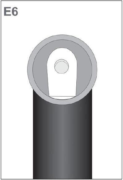
2.54 Align the eye of the cable lug with the threaded pin and push the screened connector onto the bushing.<br> <br>There is no need to push it completely onto the bushing. It is sufficient when the threaded pin protrudes the lug.
-
-
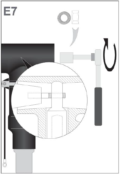
2.55 Insert the Nordlock washer and hex nut. Tighten the hex nut onto the threaded pin with a spanner (24 mm) at a torque of 100 Nm.
-
-
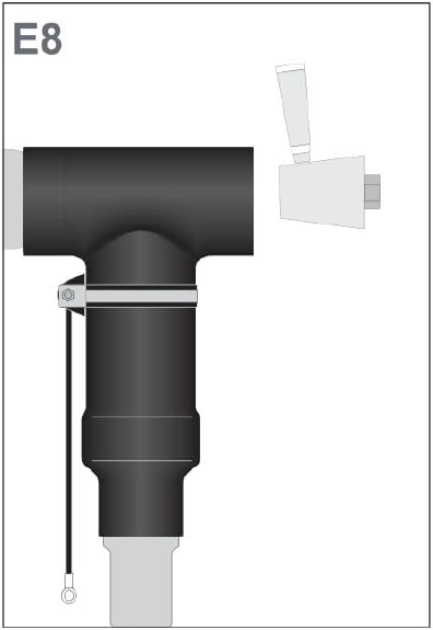
2.56 Clean the inner surface of connector back end and apply a thin layer of assembly lubricant. Do the same with the conical interface of the back plug as shown.
-
-
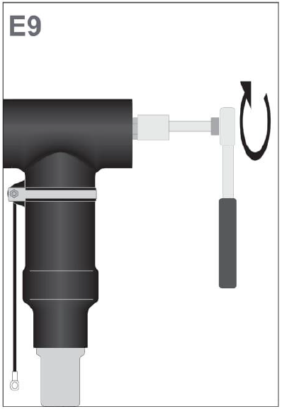
2.57 Insert the back plug and screw it into place using a spanner (24 mm) at a torque of 70 Nm.
-
-
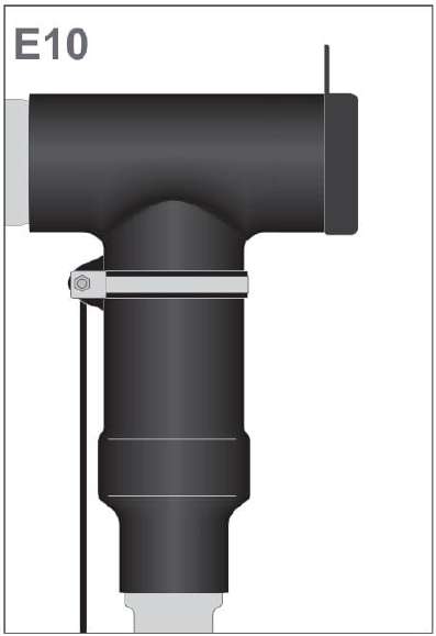
2.58 Turn the covering cap inside out and push its pin into the socket in the backplug's electrode.<br> <br>Then flip the sidewall of the cap onto the connector as shown.
-
-
2.59 Ensure that the grounding lead of the RSTF body is fastened tightly.<br><br>Perform connection to ground.<br><br>Perform connections to ground (RSTF body and earthing braid). For switchgear connectors: Use 70 Nm for M12 connections.<br><br>For good mechanical strength fasten protected core as close as possible to the connector.
-
-
2.60 Screened separable connector installation completed.
-
-
2.61 Photograph including date/time stamp shall be taken showing the installed screened separable connector.
-
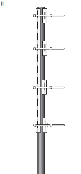
2.62 Install the remaining cable cleats inside the switchgear and below on the cable ladder.<br><br>Tighten securely with Allen Key. It is recommended to use hand tools. Maximum torque for bolts of the cleats: 5 Nm
-
2.63 Photograph including date/time stamp shall be taken showing the cleats inside the switchgear compartment.
-
2.64 Install base plates according to Operating Instructions 8VMI (925 00100 174 D), Doc No.: HKZ14-SGRE-WTG-MA-0004.
-
-
2.65 Install the switchgear arcing plate according to Operating Instructions 8VMI (925 00100 174 D), Doc No.: HKZ14-SGRE-WTG-MA-0004.
-
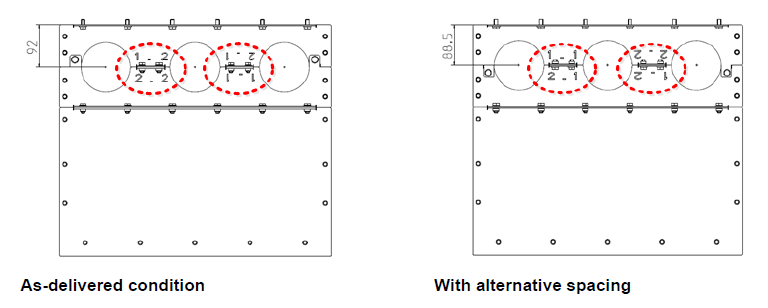
2.66 The distance between the arc protection plates and the cable T-connectors must not exceed 15 mm. The arc protectors must not touch the cable T connectors.
-
2.67 Photograph including date/time stamp shall be taken showing the switchgear compartment.
-
2.68 Close the Cable Terminal Boxes according to Operating Instructions 8VMI (925 00100 174 D), Doc No.: HKZ14-SGRE-WTG-MA-0004
-
2.69 Remove any temporary cable identification markings that may have been installed during the assembly work.
-
2.70 A cable identification label shall be fitted to each power core 1m above the hang off.
-
2.71 Photograph including date/time stamp shall be taken showing cable identification label fitted above the hang off.
-
2.72 A cable identification label shall be fitted to each power core 1m below the penetration into the GIS
-
2.73 Photograph including date/time stamp shall be taken showing cable identification label fitted below the penetration.


Sub Task # 3) Completion
-
3.1 Collect all tools and waste and prepare them for lifting. Clean any stains caused.
-
3.2 Close hatches.
-
3.3 Lift off all remaining materials, waste and tools by the crane (if no other works to be done).
-
3.5 Leave structure
Sign Off
-
Signature Tower Foreman / Team leader
-
Signature Vattenfall Representative
-
Comment if applicable


 - duplicate")
 - duplicate")


 - duplicate")
 - duplicate")
