 - duplicate")


Title Page
-
Site conducted
-
Conducted on
-
Location ID
-
Cable Type
-
String
-
Cable ID
-
Prepared by
Pre Task
-
Confirm a ToolBox Talk was completed
-
Confirm Cables have been marked to final position and there is no damage present
-
Confirm Pre Term testing has been completed
-
Ensure kit size is correct before install
-
Procedure NS2244-ENG-00026 Cable Termination Power Cores OSS is available in digital or paper format and will be followed during the complete execution of the termination. The Below questions/Pictures are for QC Purposes and are *NOT* the detailed task plan also I Can confirm the procedure is available and will be followed during the termination works.
Pfisterer install before plug-in/Test
-
Ensure that the cable and Switchgear are disconnected from any voltage source and earthed.
-
Ensure there is a valid Permit in place before starting works
-
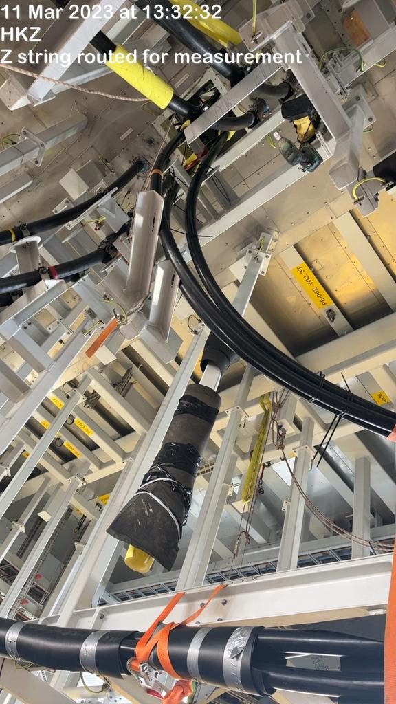
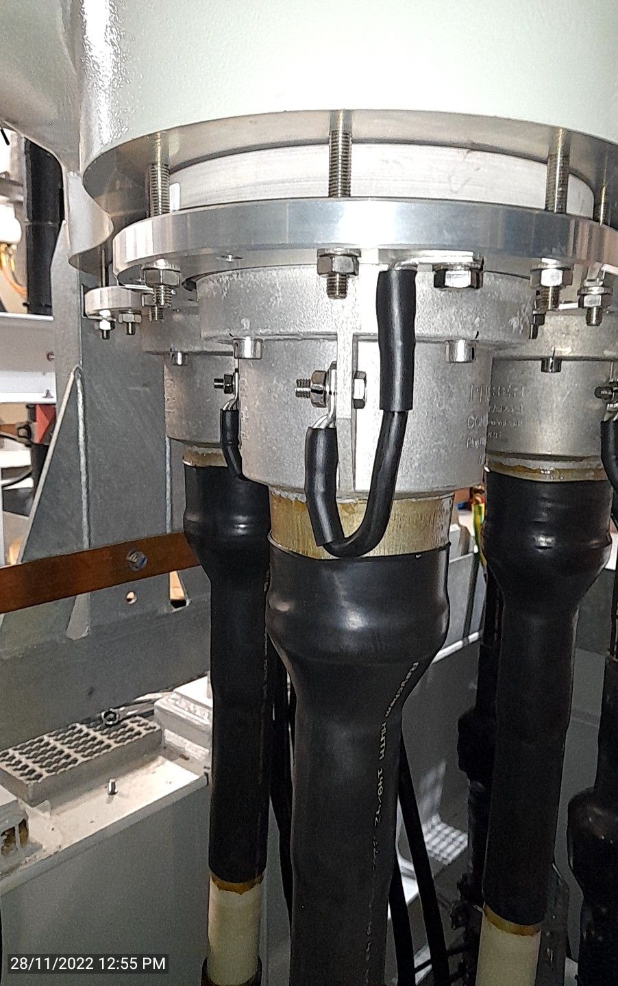
Take a picture showing the cables up and measured in the final position
-
Picture showing the cables up into position and measured in the final position
-
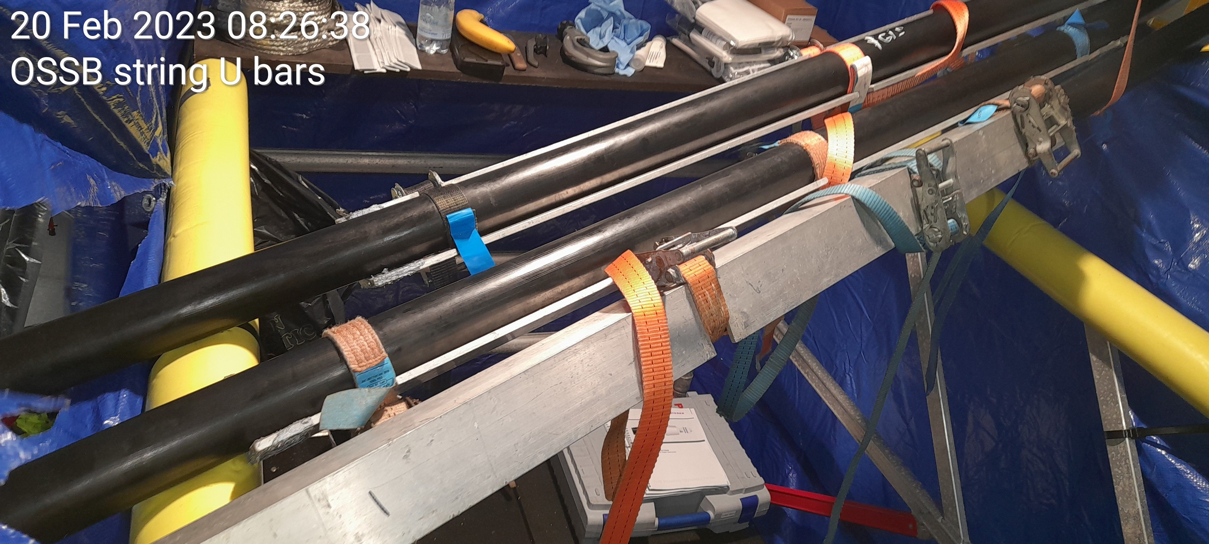
Take a picture showing straighten bars installed ensure there is excess length for screens
-
Picture showing bars installed
-
Length of time cables heated for
-
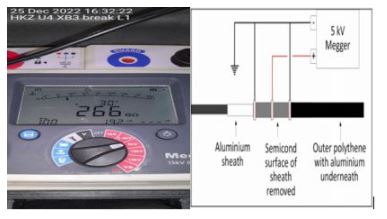
MOC-TT-007 Break Test diagram for reference 5KV for 1min (Picture required showing megger display showing result over 100MΩ)
-
L1 Picture showing Megger display proving no breakdown result over 100MΩ
-
L2 Picture showing Megger display proving no breakdown result over 100MΩ
-
L3 Picture showing Megger display proving no breakdown result over 100MΩ
-
Take a picture showing clean window
-
L1 picture showing window clean from 4 angles
-
L2 picture showing window clean from 4 angles
-
L3 picture showing window clean from 4 angles
-
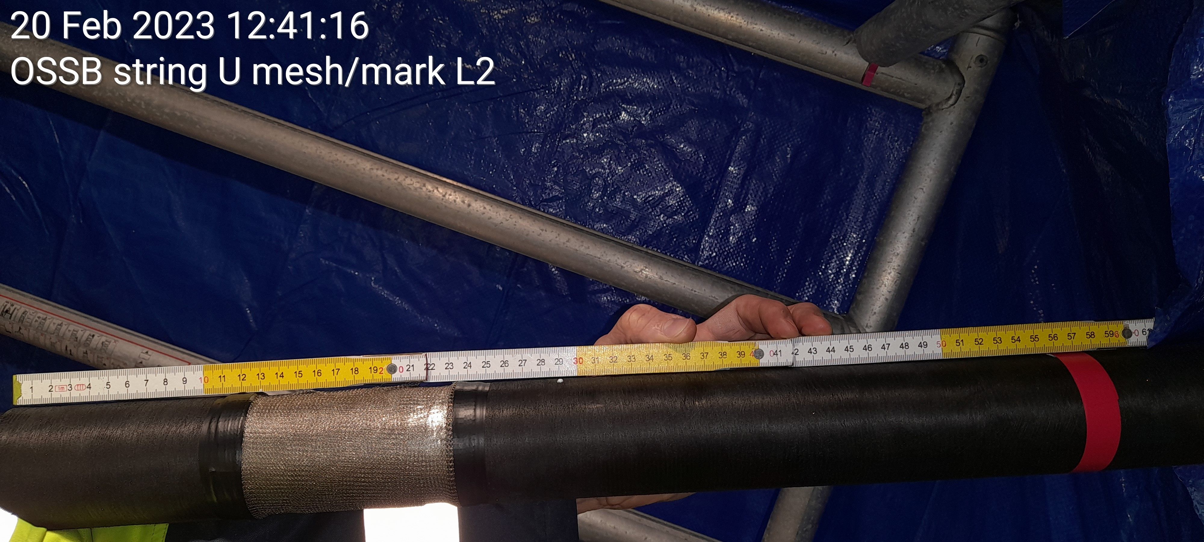
Take a picture showing mesh applied/Control Mark
-
L1 picture Showing mesh/Control mark applied
-
L2 picture Showing mesh/Control mark applied
-
L3 picture Showing mesh/Control mark applied
-
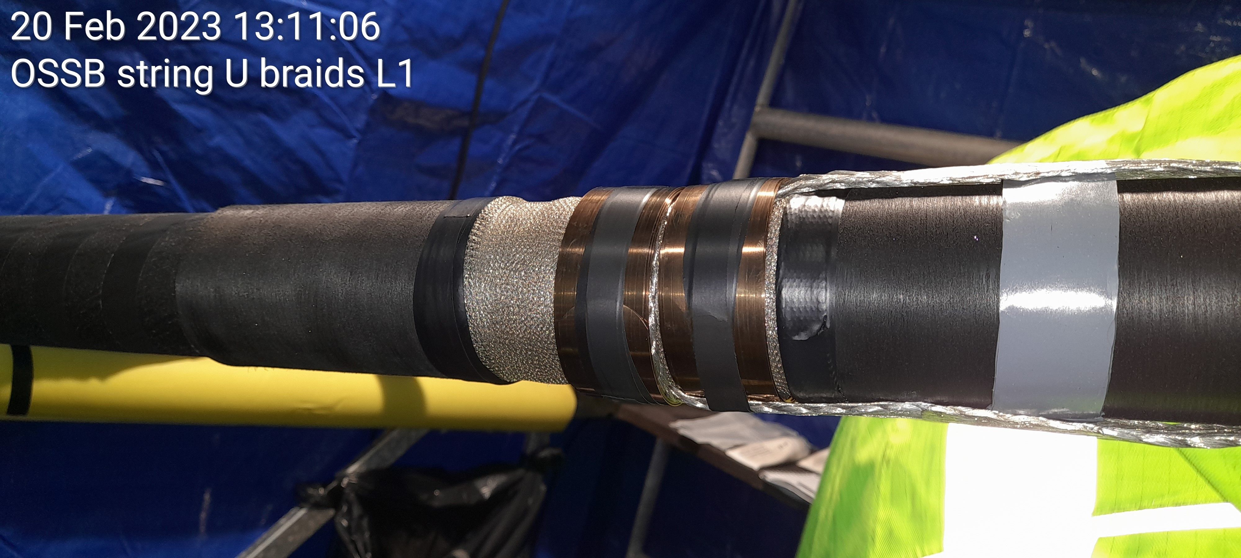
Take a picture showing braids installed
-
L1 picture showing braids installed
-
L2 picture showing braids installed
-
L3 picture showing braids installed
-
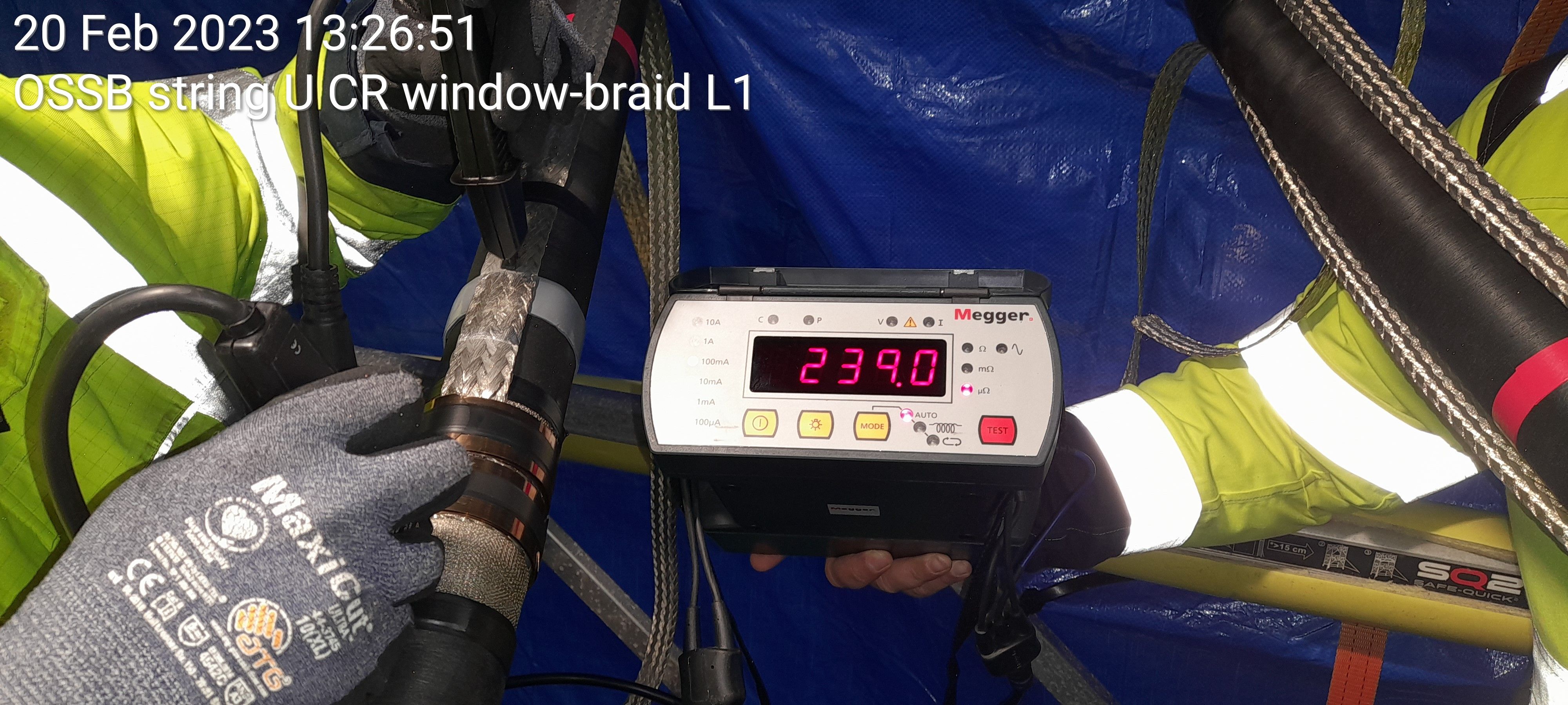
Take a picture of CR display off contact resistance between window and braids
-
L1 picture showing CR display of contact resistance between window and braid
-
L1 CR measurement
-
L2 picture showing CR display of contact resistance between window and braid
-
L2 CR measurement
-
L3 picture showing CR display of contact resistance between window and braid
-
L3 CR measurement
-
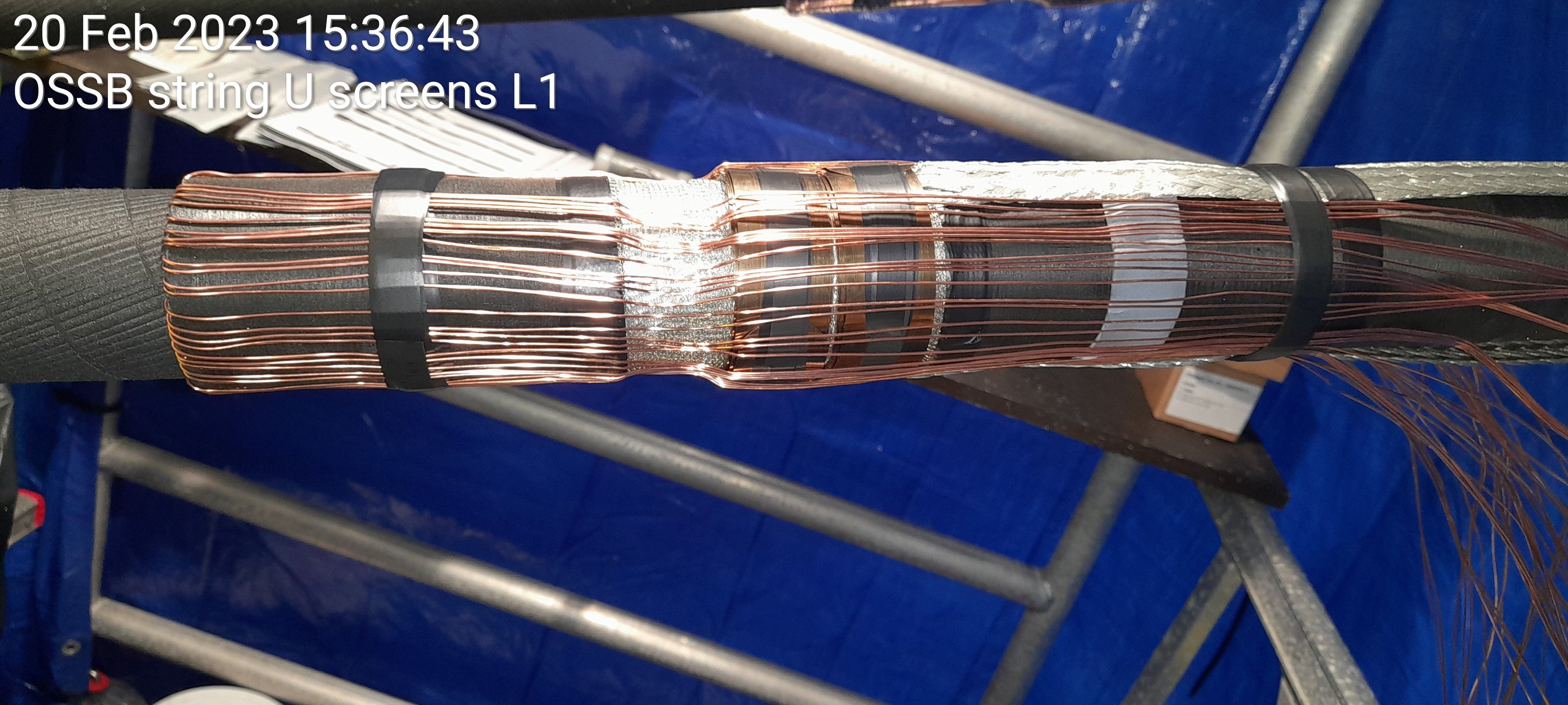
Take a picture showing screens down
-
L1 picture Showing screens down
-
L2 picture showing screens down
-
L3 picture showing screens down
-
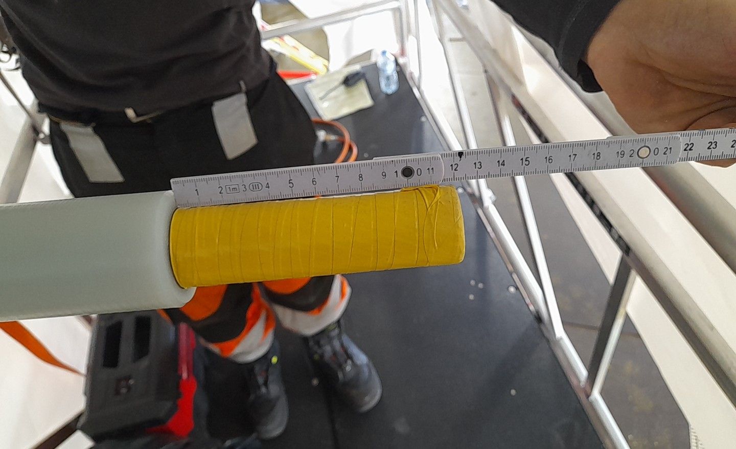
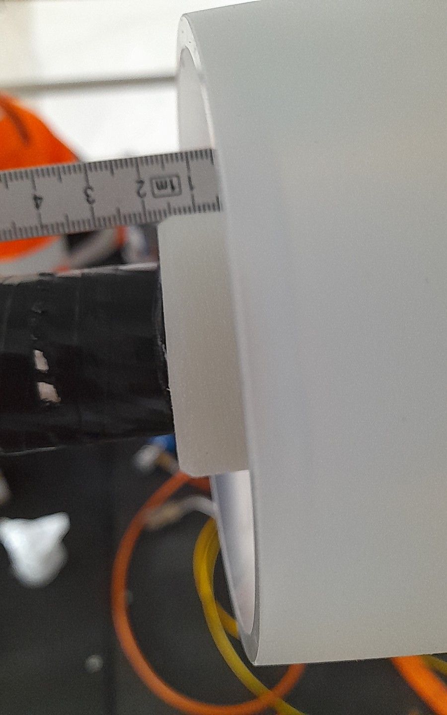
Take a picture showing core Length
-
L1 picture showing core Length with a ruler
-
L1 core length measurement
-
L2 picture showing core Length with a ruler
-
L2 core length measurement
-
L3 picture showing core Length with a ruler
-
L3 core length measurement
-
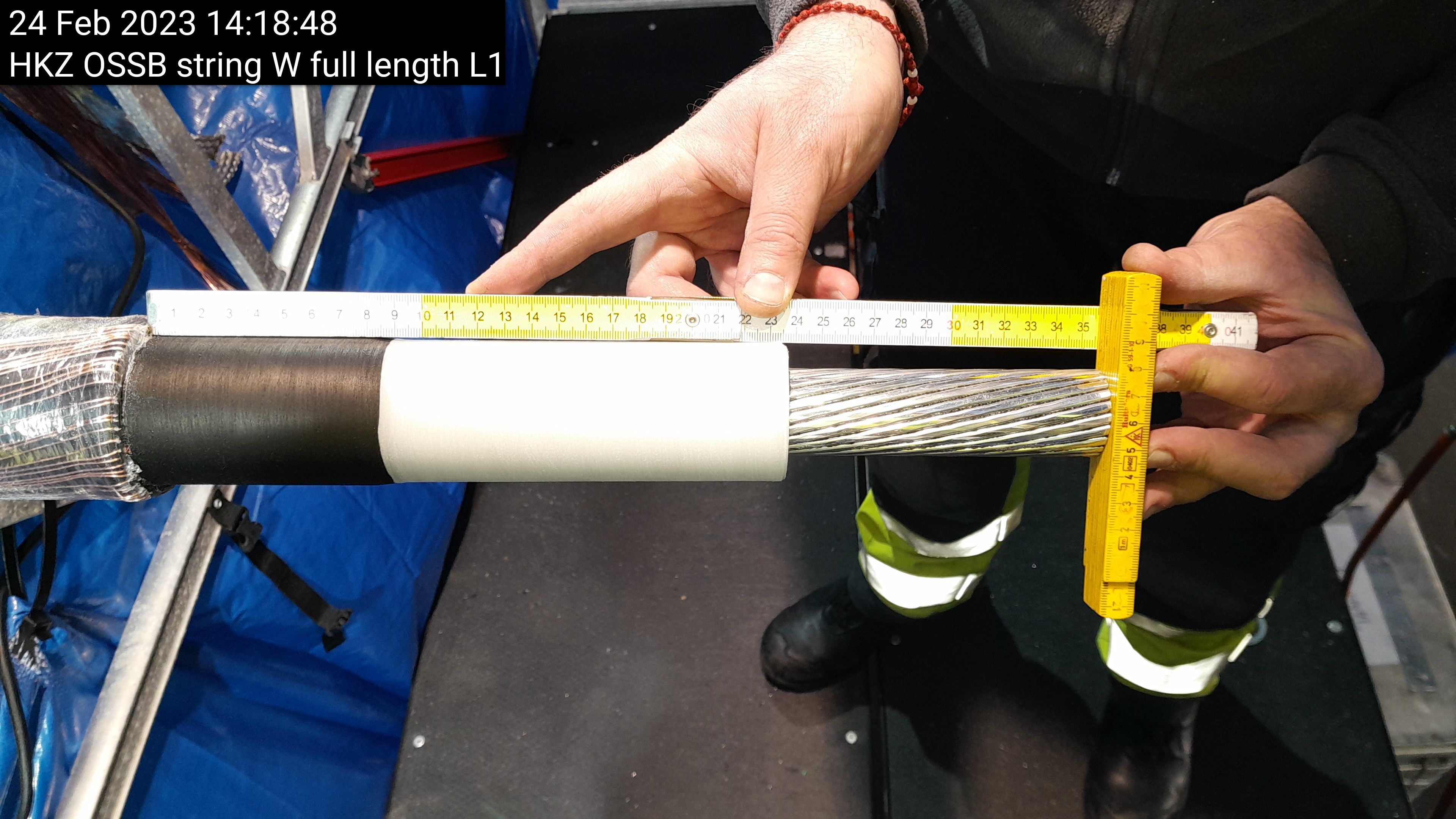
Take a picture showing full length
-
L1 Full length of prepared end with a ruler
-
L1 full length measurement
-
L2 Full length of prepared end with a ruler
-
L2 full length measurement
-
L3 Full length of prepared end with a ruler
-
L3 full length measurement
-
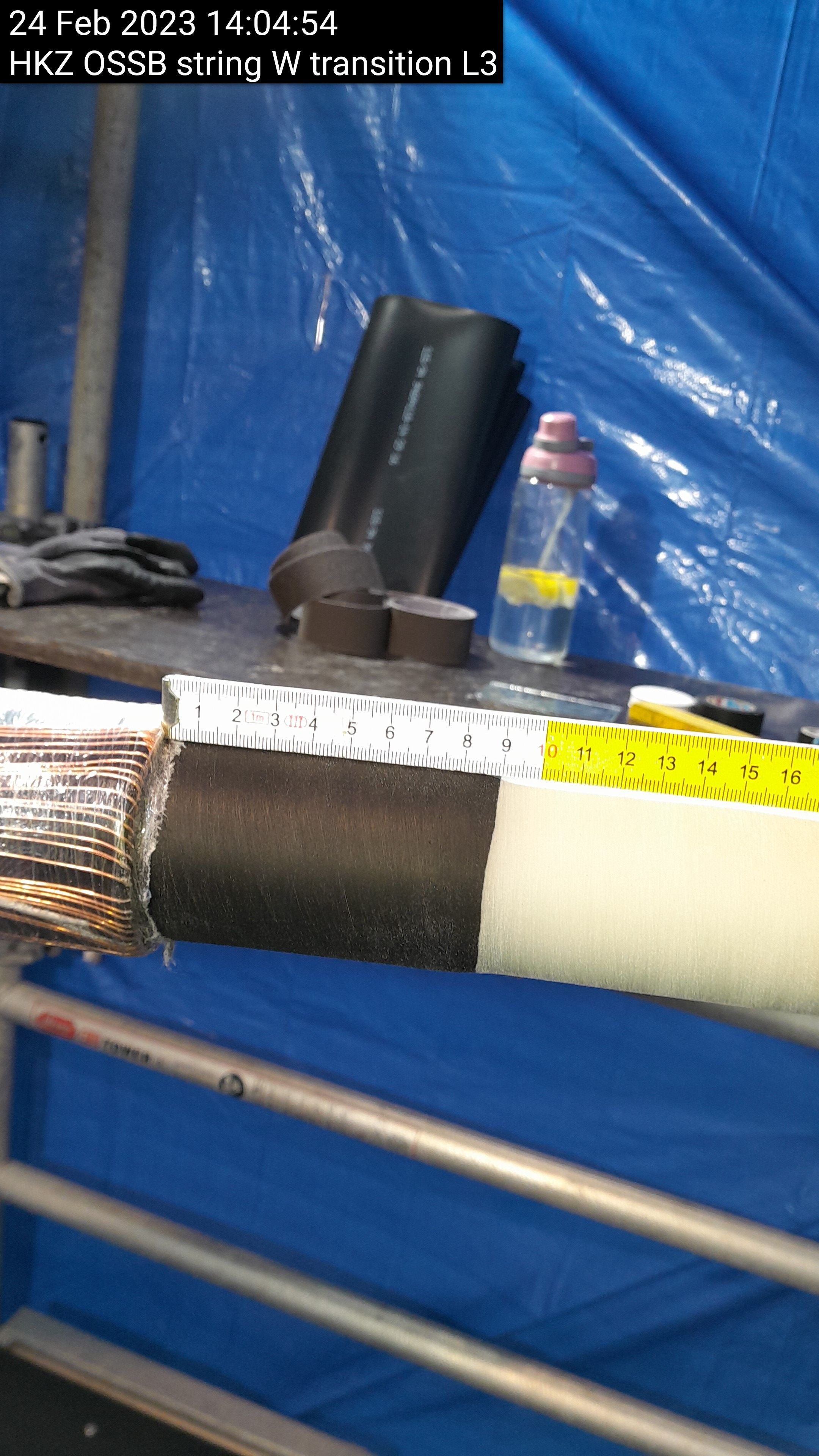
Take a Picture of the sheath to transition with a ruler
-
L1 Picture of the sheath to transition with a ruler
-
L2 Picture of the sheath to transition with a ruler
-
L3 Picture of the sheath to transition with a ruler
-
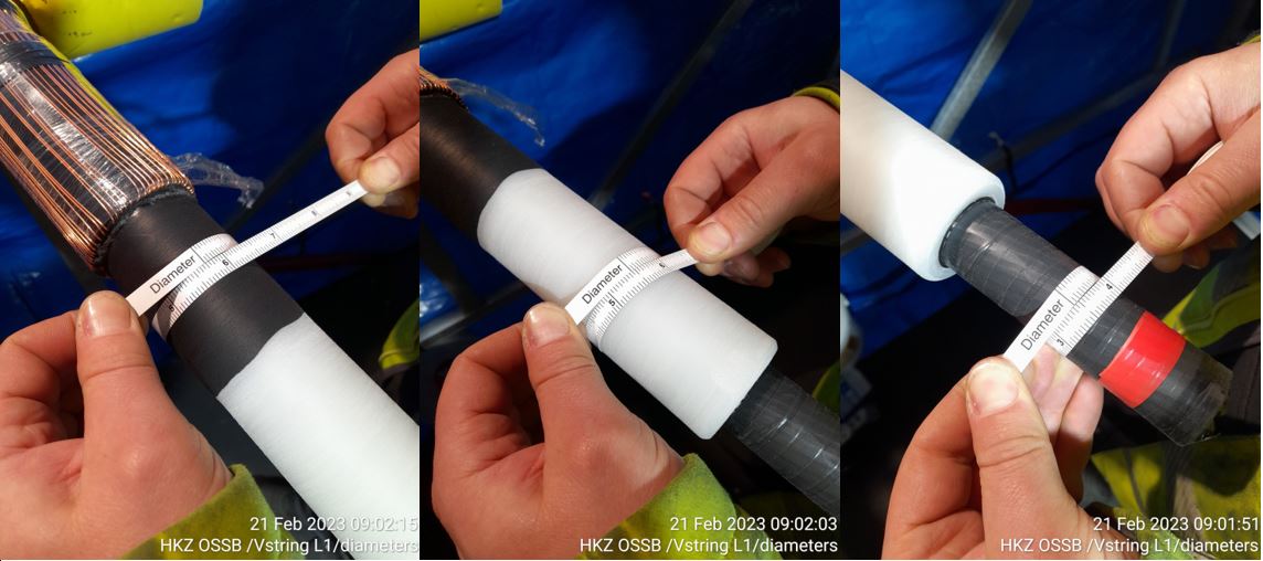
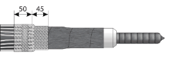
Take a picture of these diameters 3 measurements are required per phase
-
L1 Pictures showing the above diameters (3 pictures)
-
L1 diameter measurement
-
L1 diameter point two measurement
-
L1 diameter point three measurement
-
L2 Pictures showing the above diameters (3 pictures)
-
L2 diameter measurement
-
L2 diameter point two measurement
-
L2 diameter point three measurement
-
L3 Pictures showing the above diameters (3 pictures)
-
L3 diameter measurement
-
L3 diameter point two measurement
-
L3 diameter point three measurement
-
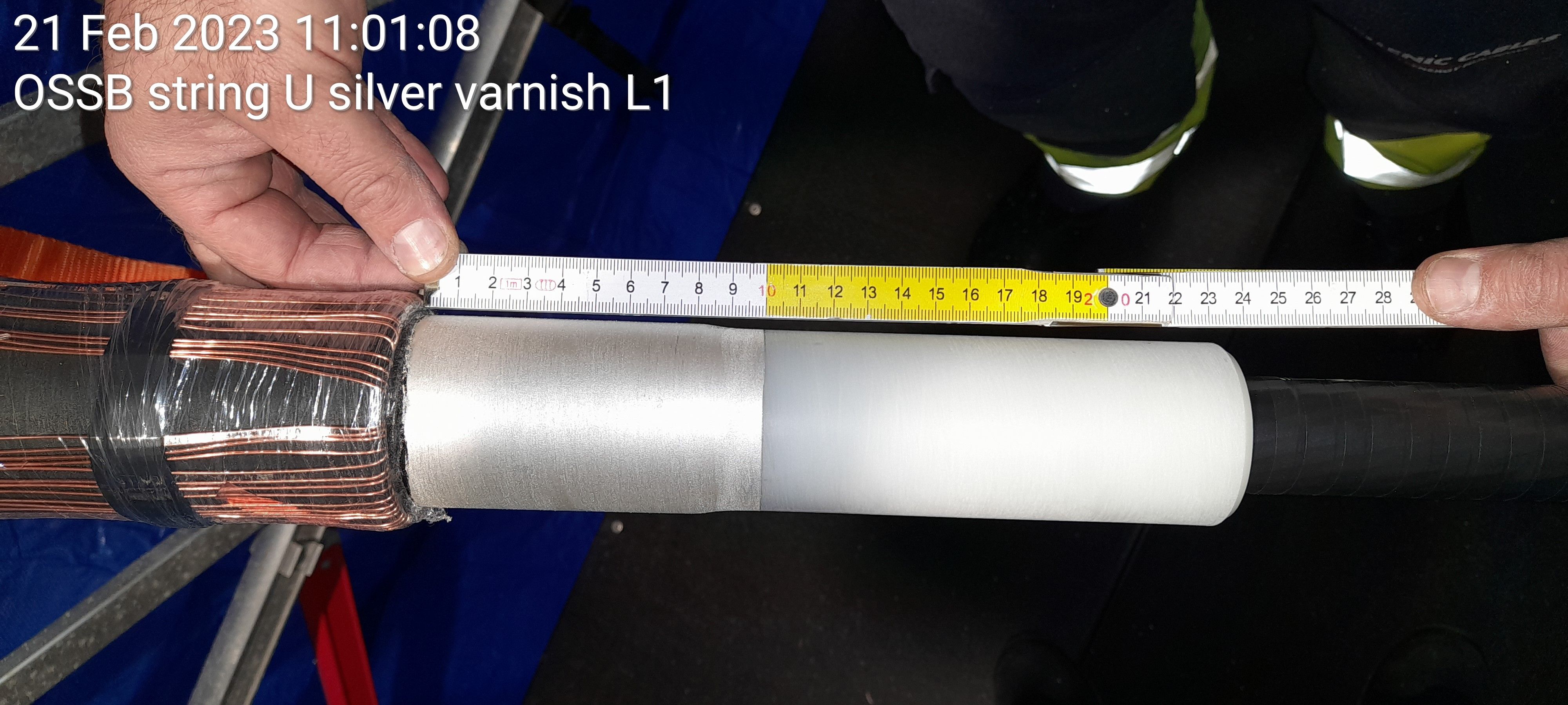
Take a picture showing silver varnish applied with a ruler
-
L1 Picture of the silver varnish with a ruler against it
-
L2 Picture of the silver varnish with a ruler against it
-
L3 Picture of the silver varnish with a ruler against it
-
Take a picture showing mesh installed
-
L1 Picture showing Mesh installed
-
L2 Picture showing Mesh installed
-
L3 Picture showing Mesh installed
-
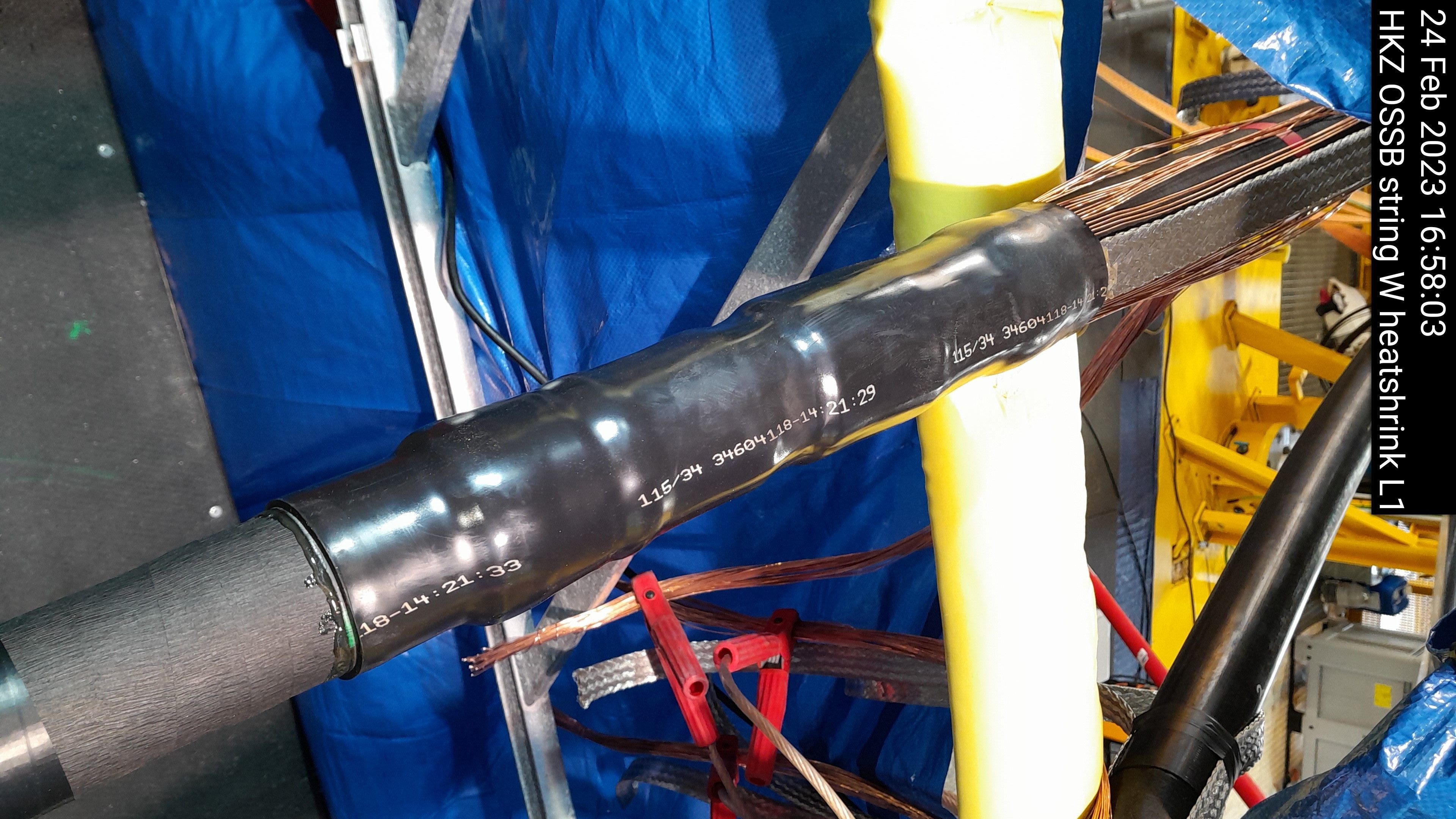
Take a picture showing installed heatshrink
-
L1 Picture showing heatshrink installed
-
L2 Picture showing heatshrink installed
-
L3 Picture showing heatshrink installed
-
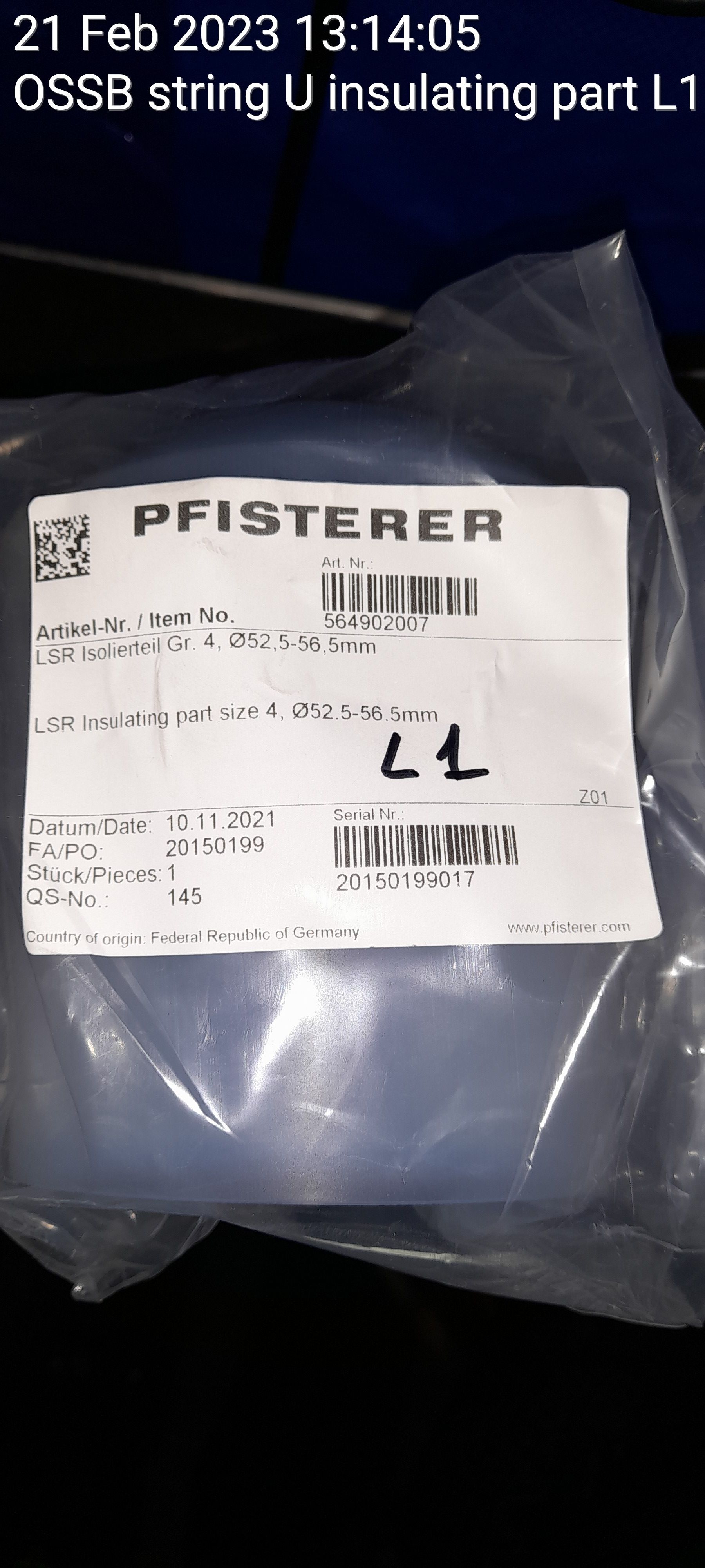
Take picture of insulating part serial number for each phase
-
L1 Picture showing insulating part serial number
-
L1 insulating part serial number
-
L2 Picture showing insulating part serial number
-
L2 insulating part serial number
-
L3 Picture showing insulating part serial number
-
L3 insulating part serial number
-
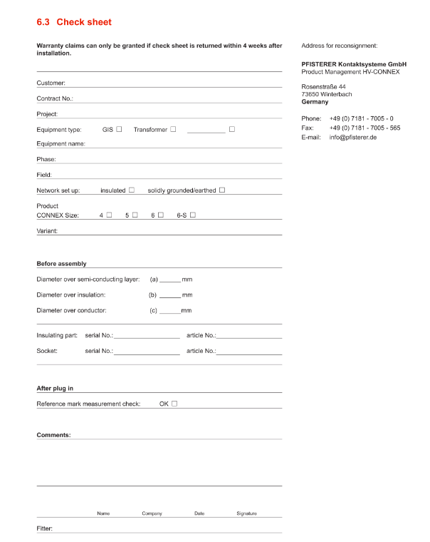
Ensure checksheet is filled out
-
Confirm document has been filled out
-
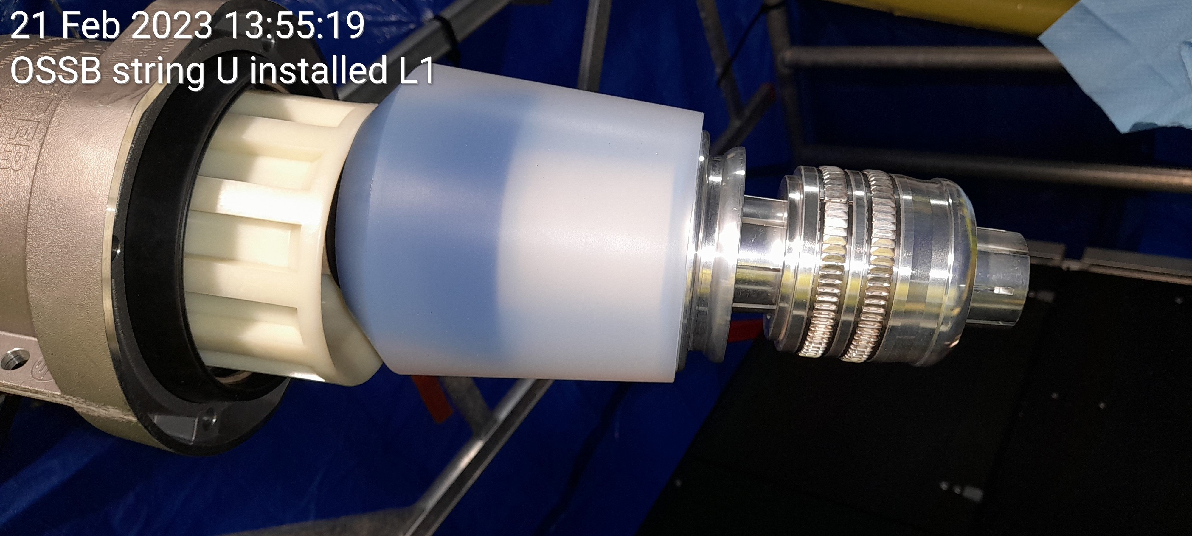
Take a picture of cone insulation part installed
-
L1 picture showing insulation part installed
-
L2 picture showing insulation part installed
-
L3 picture showing insulation part installed
-
Take a picture showing cable end completed after compression
-
L1 picture showing cable end completed after compression
-
L2 picture showing cable end completed after compression
-
L3 picture showing cable end completed after compression
-
For information purposes next page is for test box/protective cap/plug-in pictures


Test/Plug-in
-
Take a picture showing cable in test boxes and dummy plugs installed and ready to test
-
L1 picture showing cable in test boxes and dummy plugs installed and ready to test
-
L2 picture showing cable in test boxes and dummy plugs installed and ready to test
-
L3 picture showing cable in test boxes and dummy plugs installed and ready to test
-
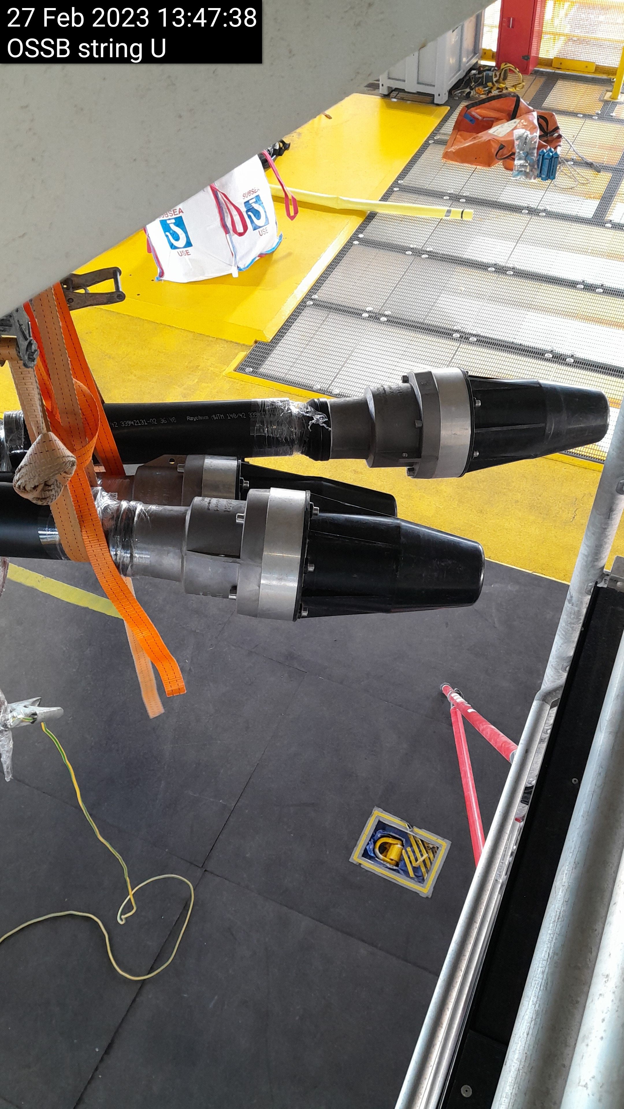
Take a picture of the protective caps installed
-
L1 picture showing protective caps installed
-
L2 picture showing protective caps installed
-
L3 picture showing protective caps installed
-
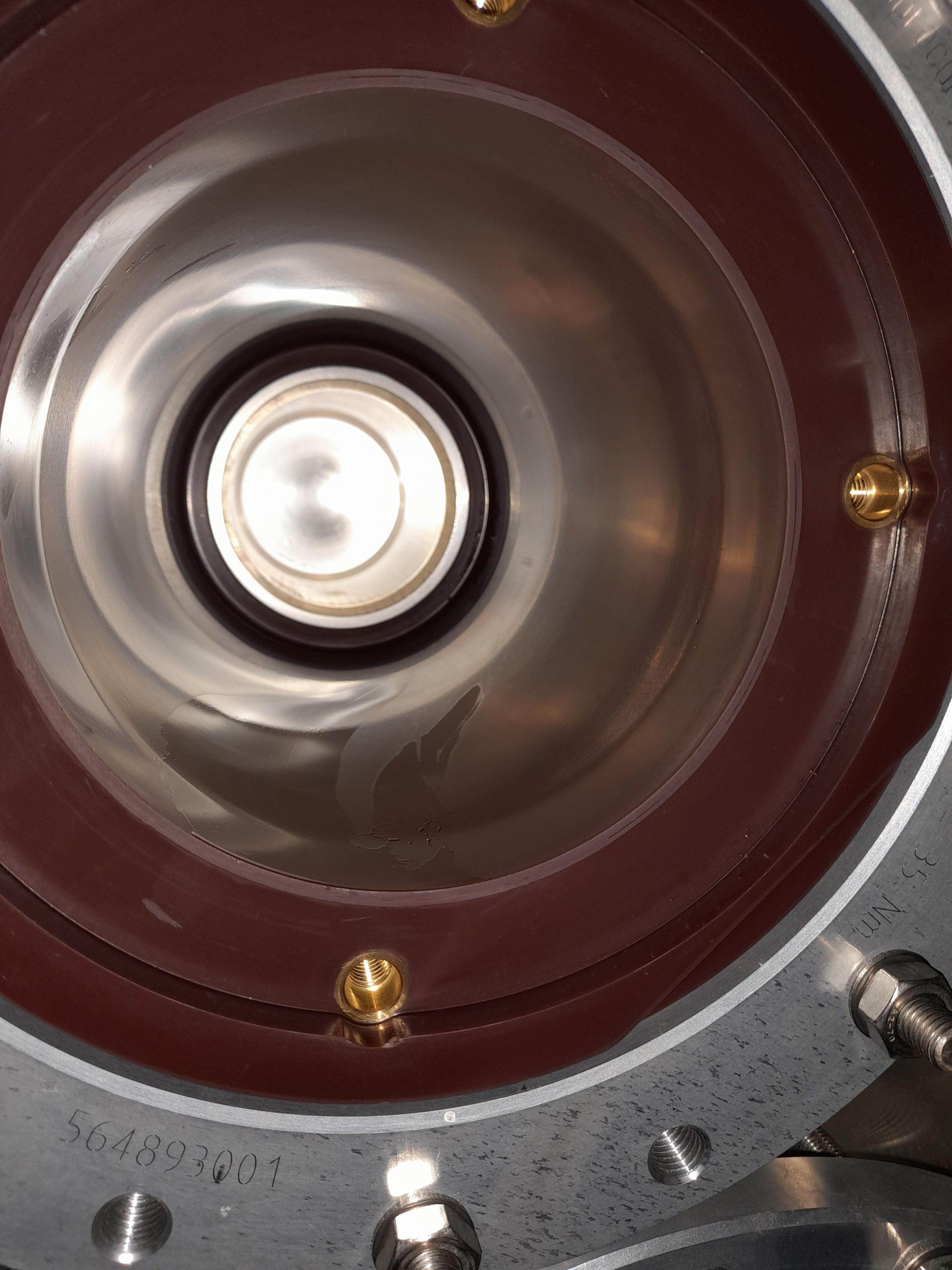
Take a picture inside socket before plugging-in ensure there is no marks/damage
-
L1 picture of inside socket before plugging-in ensure there is no marks/damage
-
L2 picture of inside socket before plugging-in ensure there is no marks/damage
-
L3 picture of inside socket before plugging-in ensure there is no marks/damage
-
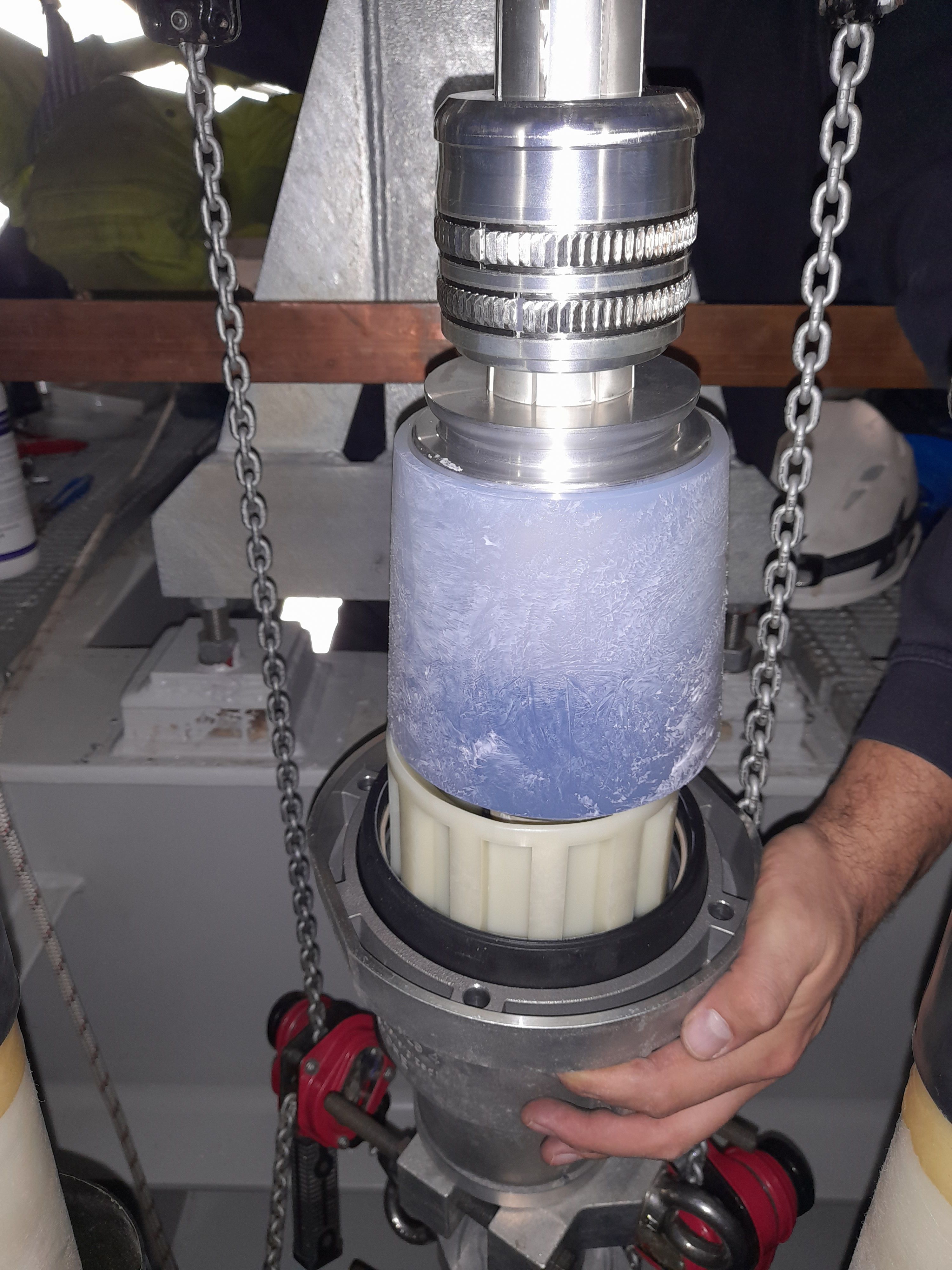
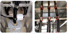
Picture with cable into position ready for plug-in sat under the socket as shown in the example
-
L1 picture showing cable ready to plug-in sat under the socket
-
L2 picture showing cable ready to plug-in sat under the socket
-
L3 picture showing cable ready to plug-in sat under the socket
-
Take a picture when cable is plugged-in/heatshrink installed showing the torqued and marked pfisterer bolts
-
L1 picture showing cable plugged-in/heatshrink installed showing the torqued and marked pfisterer bolts
-
L2 picture showing cable plugged-in/heatshrink installed showing the torqued and marked pfisterer bolts
-
L3 picture showing cable plugged-in/heatshrink installed showing the torqued and marked pfisterer bolts
-
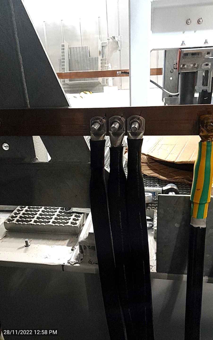
Take a picture showing earthing completed and connected to the earthbar
-
L1 Picture showing earthing complete connected to the earth bar
-
L2 Picture showing earthing complete connected to the earth bar
-
L3 Picture showing earthing complete connected to the earth bar
-
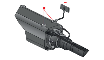
Take a picture showing the bellhouse earthing straps installed
-
L1 picture showing bellhouse earthing straps installed
-
L2 picture showing bellhouse earthing straps installed
-
L3 picture showing bellhouse earthing straps installed
-
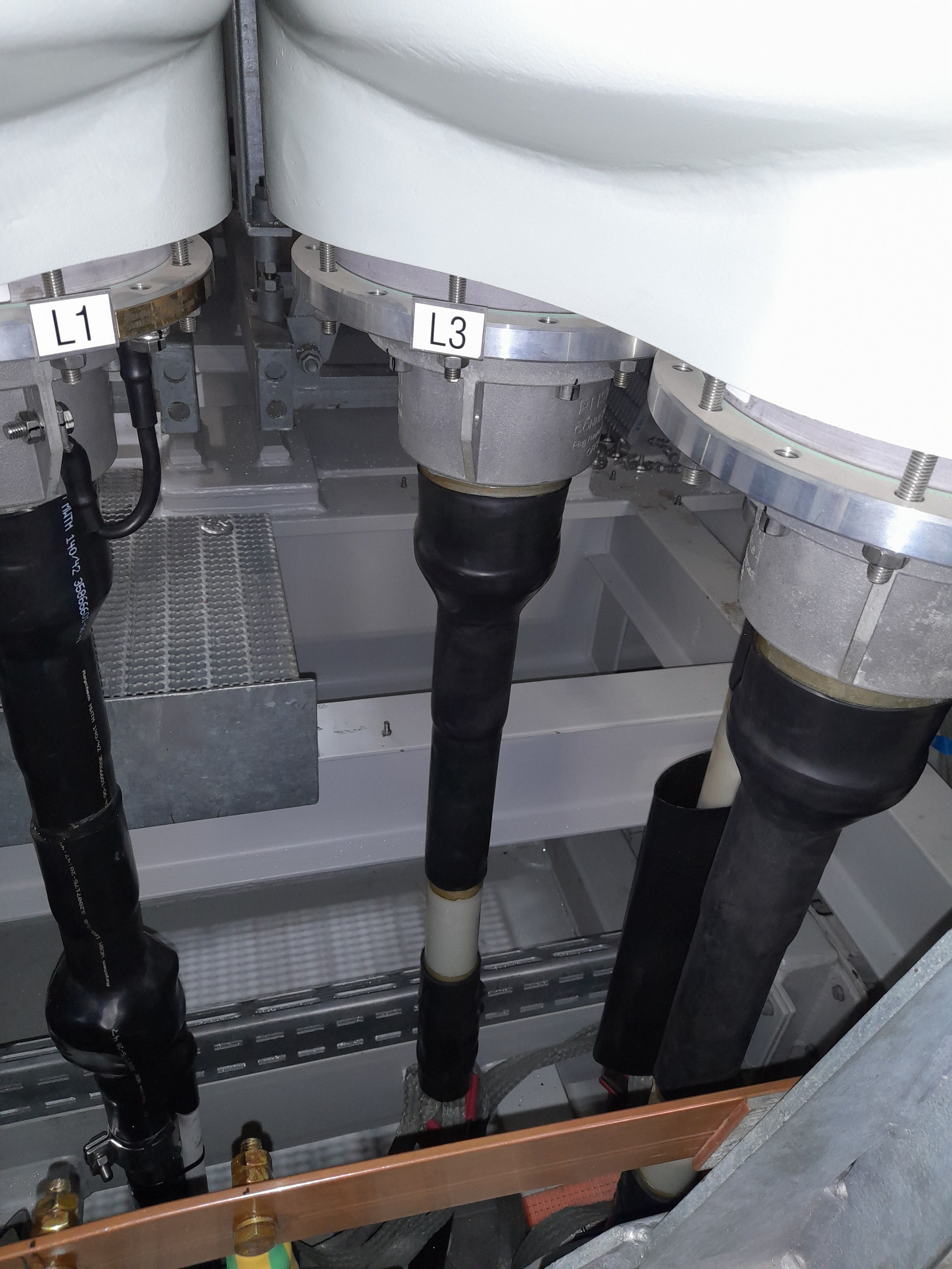
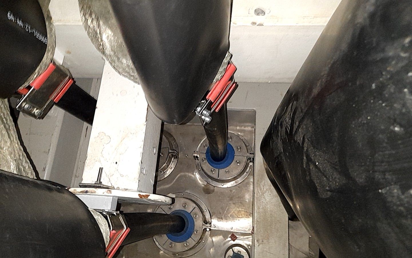
Take a picture showing the cable straight until the first cleat
-
L1 picture showing cable straight until first cleat
-
L2 picture showing cable straight until first cleat
-
L3 picture showing cable straight until first cleat
-
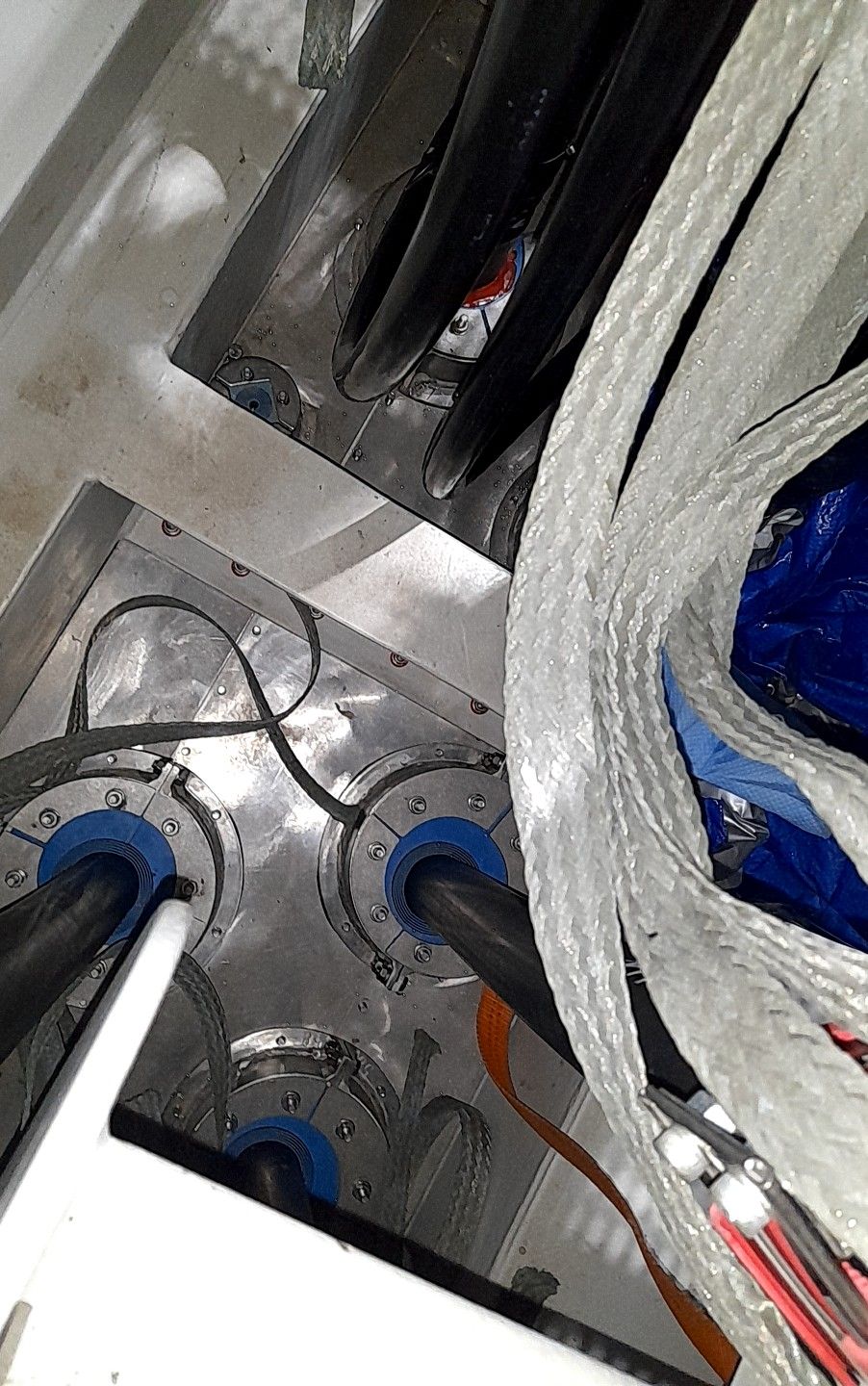
Take a picture showing roxtec plate reinstalled from above
-
Picture showing roxtec plate reinstalled from above
-
Take a picture showing installed labels where required (example pictures only)
-
Picture showing the installed labels where required
Sign off
-
I Can confirm the termination has been executed according to NS2244-ENG-00026 Cable Termination Power Cores OSS Procedure.
-
Client Rep Present
-
Client Signature
-
V&SH Tower team Lead (Add notes if full termination wasn't done by one jointer showing which points where done)
-
SOC HV Supervisor to review and confirm installation work carried out satisfactory meeting the specified requirements and tick complete.
-
SOC HV Supervsior
-
Comment if applicable


 - duplicate")
 - duplicate")


 - duplicate")
 - duplicate")
