


Title Page
-
Site conducted
-
Conducted on
-
Location
-
Cable ID
-
Prepared by
-
Tick
- FOU - FO Cable Routing and Termination
-
Publication date: 01-02-2022
SOC Revision: 1
Document name: NS2244-ENG-00027
Complete file attached
Sub-Task #1 Preparation
-
1.1 Perform Toolbox talk
-
Check for a valid permit and review the required safety measures
Attached TRA M-00011431 -
1.2 Perform Radio communication check with ISV
-
1.3 Lift tools from ISV to EWP
-
Perform dropped object sweep, if found select "At Risk".
-
Report potential dropped object via HOC card to the vessel.
-
1.4 Check that accessories of the splice box and all material needed for the splicing are available. <br> Check that all tools required for the work is available and in good condition.
Sub-Task #2 FO Cable Routing & Termination
-
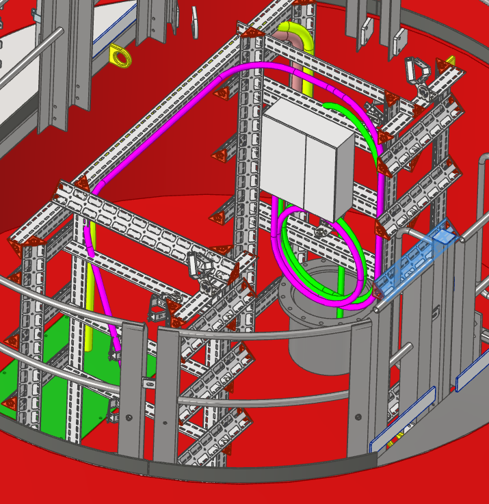
2.1 Route the submarine fiber optical cable to the splice box’s location to mark the bushing position on the cable.
-
The FO splice box will be installed on the inner side of the cable racking above the hang-off, the box can be installed on either side, this being dependent upon which cable is pulled in first.
-
2.2 Refer to the FO cable routing sketch for more clarifications, NS2244-SKT-0035 [attachment-5]
-
2.3 Record the batch number and the meter length marking as embossed on the TKF Fibre Cables.
-
2.4 FO-Cables shall be guided below the interlink beam of the racking to have them protected from the stored power cores.
-
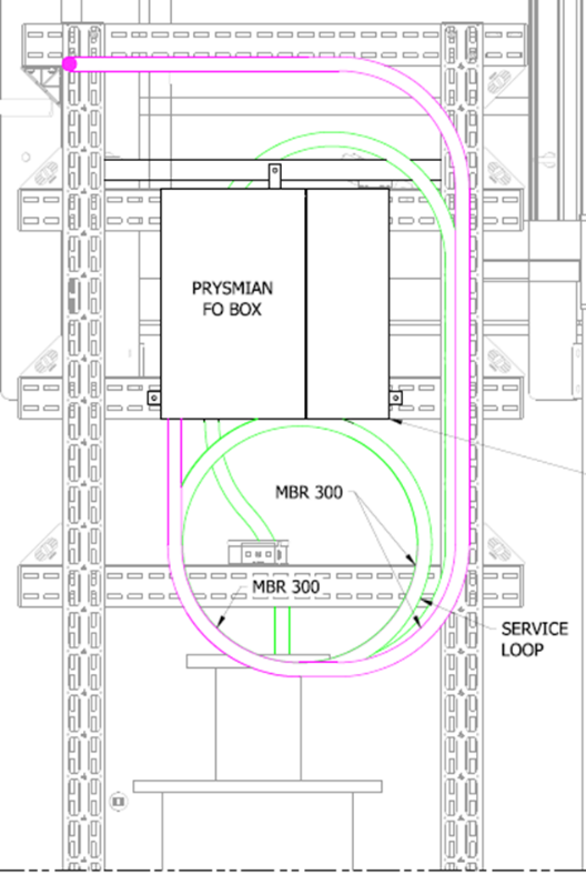
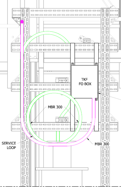
2.5 Create a service loop of the submarine FOC near the FO splice box
-
No service loop is necessary for the far reach submarine FOC.
-
2.6 Make sure that the FOC MBR is not breached!
-
TKF FOC
Diameter of the service loop has to be at least 1.9 meters.
MBR: 300 mm
PPL FOC
Diameter of the service loop has to be at least 1.9 meters.
MBR: 300 mm -
2.7 Measure and record the diameter of the maintenance loops.
-
2.8 Fix the cable to the structure with two cable ties forming an X at least every meter over the cable.
-
2.9 Photographs including date/time stamp shall be taken showing the routed cable.
-
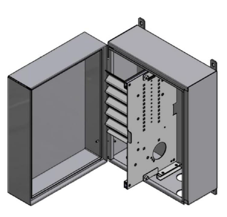
2.10 Get the splice box and place it on a table to have a convenient work place.
-
TKF FO Box
-
PPL two door FO Box
-
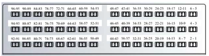
2.11 Install the pre-manufactured adaptor identification labels to the TKF cabinet as per the Splice Plan.
-
-
2.12 Ensure the adaptor labelling within the Prysmian patch panel have been pre-installed.
-
-
2.13 Add 2.5 meters to the mark of the bushing location, if there is any excess cable, extend the maintenance loop or lose the excess in the cable route
-
*Do not cut the fibre cable*.
-
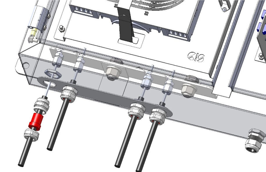
2.14 Pull the bushing assembly over the cable, feed the cable through the box and strip the outer sheath, the stainless-steel tube to access the fibres. <br><br>Follow the instruction manual of the splice box for the required lengths.
-
2.15 For TKF FOC, follow the FO Splice box installation manual
-
-
TKF: Fibre Box Installation Manual - Doc. No. 34014-IIN-OF0260994
-
2.16 For PPL FOC, follow the FO Splice box installation manual
-
-
Prysmian: Fibre Box Installation Manual - Doc. No. PPL18301-SE-PRO-005
-
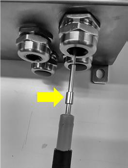
2.17 Assemble the cable bushing and the earthing kit according to the splice box manual. <br> Coil the spare fibre length in the splice cassette. <br> Make sure that at any sharp edges the fibers are protected
-
2.18 Photographs including date/time stamp shall be taken showing the earthing of the fibre optic cable steel tube.
-
2.19 Clean and separate the fibres, care should be taken while carrying out this task.
-
2.20 Start to splice the fibres according to SOC fibre Optic Cable Splicing Instruction GEN-SUP-0707 and the splice plan.
-
All splices are to be installed with a splice protector.
-
Arrange the completed fibers in the splice cassette.
-
SOC fibre Optic Cable Splicing Instruction GEN-SUP-0707
-
HKZ 1&2 - Splice Plan
-
HKZ 3&4 - Splice Plan
-
2.21 Photographs including date/time stamp shall be taken showing every splice cassette.
-
2.22 Photographs including date/time stamp shall be taken showing the complete FO splice box with the bushings visible.
-
2.23 Close the splice box and install it to the structure according to the splice box manual
-
Prysmian FO Box
-
2.19
-
2.24 The smaller TKF splice box should to the right side of the racking to get the FO Cable straight into the box maintaining the FO-Cable MBR
-
2.25 Reroute and fix the service loop (if applicable) close to splice box
-
2.26 Photographs including date/time stamp shall be taken showing the finally installed splice box.
-
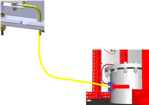
2.27 Route and connect the earthing cable to the nearest earthing point on the structure.
-
-
2.28 Photographs including date/time stamp shall be taken showing the splice box external earthing.
-
2.29 Attach the cable identification label to the fibre optic cable above the hang off.
-
2.30 Photographs including date/time stamp shall be taken showing the cable identification label installed in Step 2.29.
-
2.31 Attach the cable identification label to the fibre optic cable just below the fibre optic box.
-
2.32 Photographs including date/time stamp shall be taken showing the cable identification label installed in Step 2.31.
-
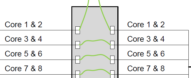
2.33 Following post-termination testing install the patch leads interconnecting the incoming subsea cable with the outgoing subsea cable as detailed in the Splice Plan.
-
2.34 Photographs including date/time stamp shall be taken showing the patch leads installed in Step 2.33.
-
Sample Patch
-
HKZ 1&2 - Splice Plan
-
HKZ 3&4 - Splice Plan


Sub-Task #3 Completion
-
Are you performing this Sub-Task
-
3.1 Normalize any structures removed
-
3.2 Collect all tools and waste and pack them for protection. Clean any stains caused
-
3.3 Lift off tools using the crane of the ISV (if no other works to be done).
-
3.4 Leave Structure.
Sign off
-
Client present?
-
No Client present
-
Client Representative
-
Comment if applicable
-
SOC Tower Team Leader
-
Comment if applicable


 - duplicate")
 - duplicate")

 - duplicate")
 - duplicate")
 - duplicate")
