


Title Page
-
Site conducted
-
Conducted on
-
Location
-
Cable ID
-
Prepared by
-
Tick
Sub-Task #1 Preparation
-
1.1 Status of installation: both ends of the cable are fully terminated, a test team is available on both structures.
-
1.2 Perform Toolbox talk
-
Toolbox Talk
Check for a valid permit to work (PTW) and review required safety measures
• For the OSS ensure to apply and obtain PTW from TenneT and Petrofac system.
• For FOU ensure to apply and obtain PTW from Vattenfall
Attached TRA M-00011431 -
1.3 This task plan covers both locations (both cable ends) and both types of structures (MP and OSS). End A is equipped with the test equipment and is leading the operations, Remote end / End B is assisting from the far end of the cable.
-
1.4 Verify your location, the cable ID, cable route and switchgear location and ID.
-
1.5 Check in over the radio with the transfer vessel and neighbouring teams so that everybody is aware of ongoing works.
-
1.6 Check that all tools and test equipment required for the work is available and in good condition, and calibration is still valid.
-
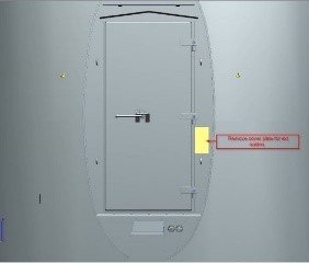
1.7 Check cable ends are secured and safe and that if any personnel are present, they are authorised to be so and where applicable safety warning notices are fixed to warn that the cable is under test.
-
1.8 Establish and test reliable two-way radio communication between cable test end and if applicable personnel present at the remote non-test end.
-
1.9 Ensure that the cable is disconnected from any voltage source and is earthed. Check for a valid Permit to Work / Sanction for Test.
-
1.10 Gain access to the cable ends.<br>WTG: open the cable compartment of the switchgear from the side. Unscrew the bolts ad remove the compartment cover according to the manual.


Sub-Task #2 Damped AC Test
-
7.1 ELECTROCUTION HAZARD
Insulation Resistance /Damped AC Testing presents an electric shock hazard to personnel and additional precautions must be taken due to the applied test voltage. -
7.2 The Vattenfall Senior Authorised Person has handed over the Sanction for Test, and briefed / displayed to the Work Party all of the implemented Safety Regulations required to achieve Safety from the System on the Circuit under Test, including but not limited to:<br>• Isolations<br>• Locked, Secured against Reconnection.<br>• Proved Dead at the Place of Work.<br>• Switchgear Earth Applied.<br>• Provide protection against adjacent or live parts.<br>• Caution Notices in Place.
-
7.3 For test purposes the ends of the core(s) under test are defined as follows:
• End A: WTG 1 / Location of Test Equipment
• End B: Offshore Substation / Last WTG -
7.4 Establish and test a reliable two-way radio communication between all personnel involved with the testing.
-
7.5 End A&B: Ensure that suitable barriers, screens, and warning signs are in place as required and that a controlled and secure means of access to both the cable end under test and the Cable Remote End is in place and effective.
-
7.6 End A: Open the Cable Termination Compartment
-
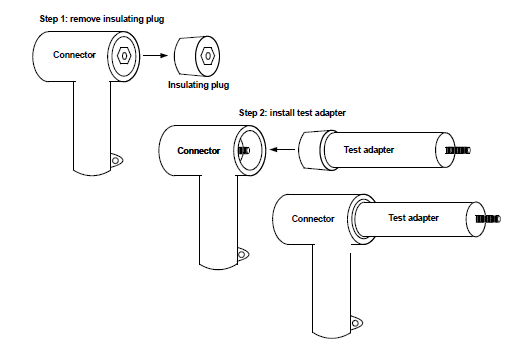
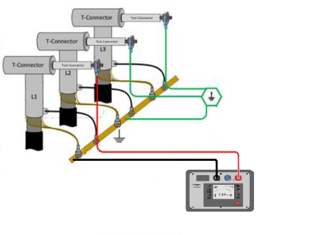
7.7 End A: Install the test adaptors onto the power cores.
-
-
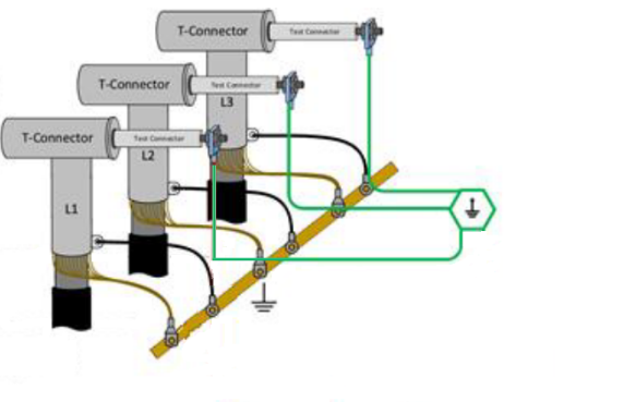
Intermediate Locations: - the test lead will be connected on to the back of a RSTF Base Connector, this shall be carried out in accordance with TKF Doc No.: 34030-IIN-OF0260994, Coupling connector 500/800 mm2 installation manual
-
End of String Locations: the test lead will be connected in the spare bay onto the bushing profile, this shall be carried out in accordance with TKF Doc No.: 34032-IIN-OF0260994, T-connector 500/800 mm2 installation manual.
-
7.8 End A: Connect a drain earth to the test adaptor positive terminals (L1, L2 & L3).
-
-
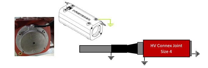
7.9 End B [OSS]: Ensure a temporary testing connection point is fitted and secured – Connector plugged into connection joint and the Conex dummy plug installed.
-
-
7.10 End B [Last WTG]: Ensure the terminations are fitted secured and the switchgear circuit earth is removed.
-
7.11 End A&B: Re-check two-way radio communications between test personnel at the cable end under test and the test personnel that shall be present at the Cable Remote End.
-
7.12 At all stages of testing a two way ‘command and confirm’ communication procedure MUST be strictly adhered to between personnel at the cable end under test and personnel at the Cable Remote End.
If at any stage during the testing procedure radio communication is lost or an instruction, communication or transmission is not confirmed by the other party the test must be stopped immediately and the cable returned to a safe condition as quickly as possible i.e. test voltage removed, cable discharged, proved dead and earthed. -
7.13 End A: Instruct personnel at the Cable Remote End that Insulation Resistance Testing will commence shortly.
-
7.14 End B: confirm.
-
7.15 End A: Select and identify Core L1 and disconnect the drain earth from the test adaptor positive terminal
-
7.16 End A: Connect the IR Test Set to Core L1.
-
-
7.17 End A: Instruct personnel at the Cable Remote End that the primary earth will be removed, and IR Testing will commence on Core L1.
-
7.18 End B: confirm.
-
7.19 End A: Request the Vattenfall SAP to remove the switchgear circuit earth.
-
7.20 End A: Carry out the Insulation Resistance Test.
-
7.21 The test voltage shall be applied for 5 minutes.
- Completed
- Not Completed
-
7.22 Photograph(s) shall be taken showing the digital readout on the test equipment.
-
7.23 End A: discharge the power core under test via IR test set after completion of the test.
-
7.24 End A: switch the test set off and apply the earth stick to Core L1.
-
7.25 End A: Request the Vattenfall SAP to reinstate the switchgear circuit earth.
-
7.26 End A: Instruct personnel at the Cable Remote End that the IR Test is complete and primary earth has been reinstated.
-
7.27 End B: confirm.
-
7.28 End A: Disconnect the IR Test Set.
-
7.29 End A: Connect portable drain earth to core L1.
-
7.30 End A: Remove the cable entry cover plate
-
-
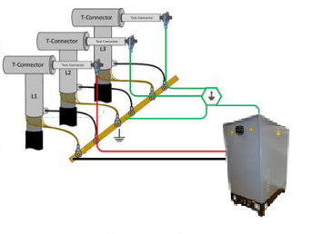
7.31 End A: Route the DAC Test Leads from the test equipment through the cable entry and into the WTG
-
7.32 End A: Connect the DAC Test Equipment to the first power core under test.
-
7.33 End A: Ensure the safety distance between the end of the test adapter and the switchgear is sufficient (min. 630 mm).
-
-
7.34 End A: Enter the cable data, identification, length, joints.
-
7.35 End A: Instruct personnel at the Cable Remote End that the primary earth will be removed, and DAC Testing will commence on Core L1.
-
7.36 End B: confirm.
-
7.37 End A: Request the Vattenfall SAP to remove the switchgear circuit earth.
-
7.38 End A: Connect the calibrator to Core L1
-
7.39 End A: Disconnect the drain earth from Core L1
-
7.40 End A: Carryout System Calibration
-
7.41 When changing the value on the calibrator the drain earth shall be reconnected to Core L1.
-
7.42 End A: Connect the drain earth to Core L1.
-
7.43 End A: Remove the calibrator from Core L1.
-
7.44 End A: Disconnect the drain earth from Core L1
-
7.45 End A: Carry out the Damped AC Voltage withstand test:<br>• Voltage level 1.75UO(RMS) starting from 0.2UO with 0.2 increments up to 1Uo and with 0.1 increments to 1.75(RMS) UO.<br>• 50 shots at 1.75(RMS)Uo for withstand test.<br>• Frequency between 20Hz to 300Hz.<br>• Tan δ and Partial discharge shall be measured and recorded simultaneously during the high voltage test.<br>• PD Mapping using TDR analysis method for localization of PD events.
-
7.46 End A: Make a 0kV shot to verify that there is no voltage
-
7.47 End A: Switch the test set off and apply the earth stick to Core L1.
-
7.48 End A: Connect the drain earth to Core L1.
-
7.49 End A: Request the Vattenfall SAP to reinstate the switchgear circuit earth.
-
7.50 End A: Instruct personnel at the Cable Remote End that the DAC Test is complete and primary earth has been reinstated.
-
7.51 End B: confirm.
-
7.52 End A&B: Repeat Steps 7.10 through to and including Step 7.50 for each HV core until testing has been completed on all three cores.
-
7.53 End B [Last WTG]: Reinstate the switchgear circuit earth.
-
7.54 End A: Remove the drain earths.
-
7.55 End A: Remove the test adaptors.
-
7.55a End A: End of String Locations - the Nexans Dummy plugs shall be fitted to the equipment bushing in accordance with the enclosed Nexans Procedure, Doc No.: IS91675-ENG - 900DR-B_G_S_0.0.0_20220712145017
-
7.56 End A: The insulation plugs shall be installed according to Cable Termination Power Core FOU, Doc No.: NS2244-ENG-00024.
-
7.57 End A: Close the switchgear compartment.
-
7.58 End A: Refit the cable entry cover plate.
-
7.59 The temporary testing connection point on the OSS will be removed and the Pfisterer Connector will be plugged into the GIS according to Cable Termination Power Cores OSS, Doc No.: NS2244-ENG-00026.


Sub-Task #3 Completion
-
Are you performing this Sub-Task
-
8.1 Normalize FO Box / or Patch panel.
-
8.2 Close and normalize HV switchgear in WTG tower and OSS.
-
8.3 Take pictures of the as left situation on WTG and OSS.
-
8.4 Close hatches/doors.
-
8.5 Close Sanction for Test.
-
8.6 Collect all tools and waste. Prepare them for lifting off the tower. Clean any stains caused
-
8.7 Lift off equipment by the crane of the ISV (if no other works to be done).
-
8.8 Leave Structure.
Sign off
-
Client present?
-
No Client present
-
Client Representative
-
Comment if applicable
-
SOC Tower Team Leader
-
Comment if applicable


 - duplicate")
 - duplicate")


 - duplicate")
 - duplicate")
 - duplicate")