


Title Page
-
Site conducted
-
Conducted on
-
Location
-
Cable ID
-
Prepared by
-
Tick
- FO Cable Routing and Termination
-
Publication date: 18-01-2022
SOC Revision: 1
Document name: NS2244-ENG-00028
Complete file attached
Sub-Task #1 Preparation
-
1.1 Perform Toolbox talk
-
Attached TRA M-00011431
-
1.2 Perform Radio communication check with ISV
-
1.3 Lift tools from ISV to the Cable Deck
-
Perform dropped object sweep, if found select "At Risk".
-
Report potential dropped object via HOC card to the vessel.
-
1.4 Check that accessories of the splice box and all material needed for the splicing are available.
-
1.5 Check that all tools required for the work is available and in good condition.
-
1.6 Check that FO topside cable racking (Green color) are installed before starting FOC termination.
-
-
1.7 Record the batch number and the meter length marking as embossed on the TKF Fibre Cables
Sub-Task #2 FO Cable Routing & Termination
-
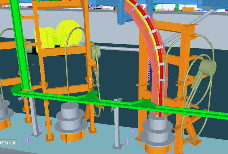
2.1 Route the submarine fiber optical cable to the location of the splice box above the hang-off for marking the bushing position on the cable.
-
The Splice box will be installed above the hang-off.
-
2.2 Create a maintenance loop measuring no more than 10m and no less than 5m whilst maintaining the minimum bend radius.
-
2.3 Make sure that the MBR of the fibre optical cable is not breached! MBR: 300 mm
-
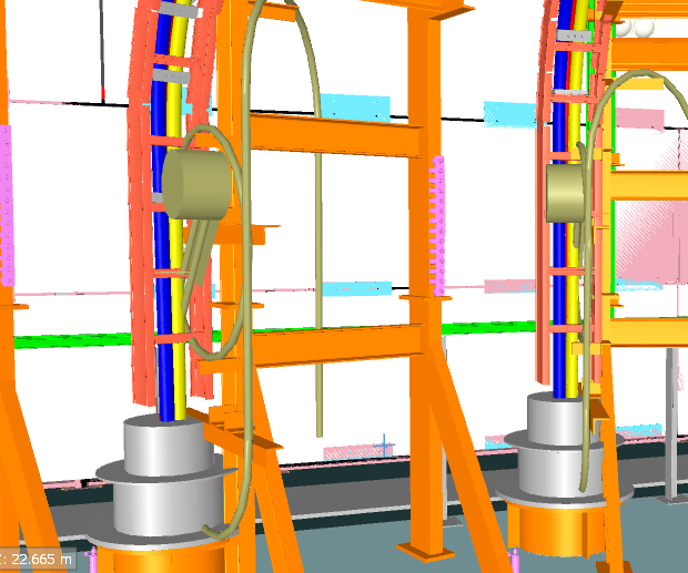
2.4 The topside cable will be stored and coiled above every FO Splice box location. <br>Unfasten the topside cable and service loop and route it to the splice box location.<br>
-
2.5 Take photographs of the routed cable
-
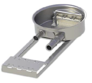
2.6 Get the splice box (TELECOMBOX 240) and place it on a table to have a convenient work place.
-
TELECOMBOX 240
-
2.7 Add 3 meters to the mark of the bushing location, the excess length can be cut off.
-
2.8 Pull the bushing assembly over the cable, feed the cable through the box and strip the outer sheath, the stainless-steel tube to access the fibres.
-
2.9 Follow the instruction manual of the splice box for the required lengths.
-
2.10 The TKF cable design entails two FO cables, hence there is a need for two cable entrances in each FO box for HKZ1-2 (OSS Alpha)<br>- Modify the fibre Optic splice boxes on OSS Alpha<br>- Replace one blind flange with a cable gland similar to the one already installed in accordance with 54351-IIN-OF0260994
-
Installation Instruction Extra Parts: 54351-IIN-OF0260994 -
2.11 Assemble the cable bushing and the earthing kit according to the splice box manual. <br>Coil the spare fibre length in the splice cassette. <br>Make sure that at any sharp edges the fibers are protected <br>
-
2.12 Clean and separate the fibres, care should be taken whilst carrying out this task.
-
2.13 Start to splice the fibres according to SOC fibre Optic Cable Splicing Instruction GEN-SUP-0707 and the splice plan. <br>All splices are to be installed with a splice protector. <br>Arrange the completed fibers in the splice cassette. <br>
-
SOC fibre Optic Cable Splicing Instruction GEN-SUP-0707
-
ATT-06 - HKZ1-2-VF-SCA-DR-008 - HKZ1&2 Splice Plan
-
ATT-07 - HKZ3-4-VF-SCA-DR-0001 - HKZ3&4 Splice Plan
-
2.14 Take photographs of every splice cassette
-
2.15 Take photographs of the complete FO splice box with the bushings visible.
-
2.16 Close the splice box and install it to the structure according to the splice box manual
-
2.17 Reroute and fix the service loop close to splice box.<br>Fix the cable to the structure with two cable ties forming an X at least every one meter over the cable.
-
2.18 Connect the earthing cable to the earthing bolt
-
2.19 Take photographs of the finally installed splice box with the maintenance loop and earthing visible.
-
2.20 Attach the cable identification label to the fibre optic cable above the hang off.
-
2.21 Take photograph of the cable identification label installed above the hang off
-
2.22 Attach the cable identification label to the fibre optic cable just below the fibre optic box.
-
2.23 Take photograph of the cable identification label installed just below the fibre optic box.
Sub-Task #3 Completion
-
Are you performing this Sub-Task
-
3.1 Normalize any structures removed
-
3.2 Collect all tools and waste and pack them for protection. Clean any stains caused
-
3.3 Lift off tools using the crane of the ISV (if no other works to be done).
-
3.4 Leave Structure.
Sign off
-
Client present?
-
No Client present
-
Client Representative
-
Comment if applicable
-
SOC Tower Team Leader
-
Comment if applicable


 - duplicate")
 - duplicate")

 - duplicate")
 - duplicate")
 - duplicate")
