 - duplicate")


Title Page
-
Site conducted
-
Conducted on
-
Location ID
-
Cable ID
-
Cable Type
-
String
-
Prepared by
Pre Task
-
Confirm a ToolBox Talk was completed
-
Confirm Pre Term testing has been completed
-
Confirm Cables are in final position
-
Procedure NS2244-ENG-00024 Cable Termination Power Cores FOU is available in digital or paper format and will be followed during the complete execution of the termination. The Below questions/Pictures are for QC Purposes and are *NOT* the detailed task plan also I Can confirm the procedure is available and will be followed during the termination works.
Connector Data/Serial Numbers
-
Confirm Kit is correct for cable size before install (Please note that all of the below information should be filled in while heat/Straighten Cables)
-
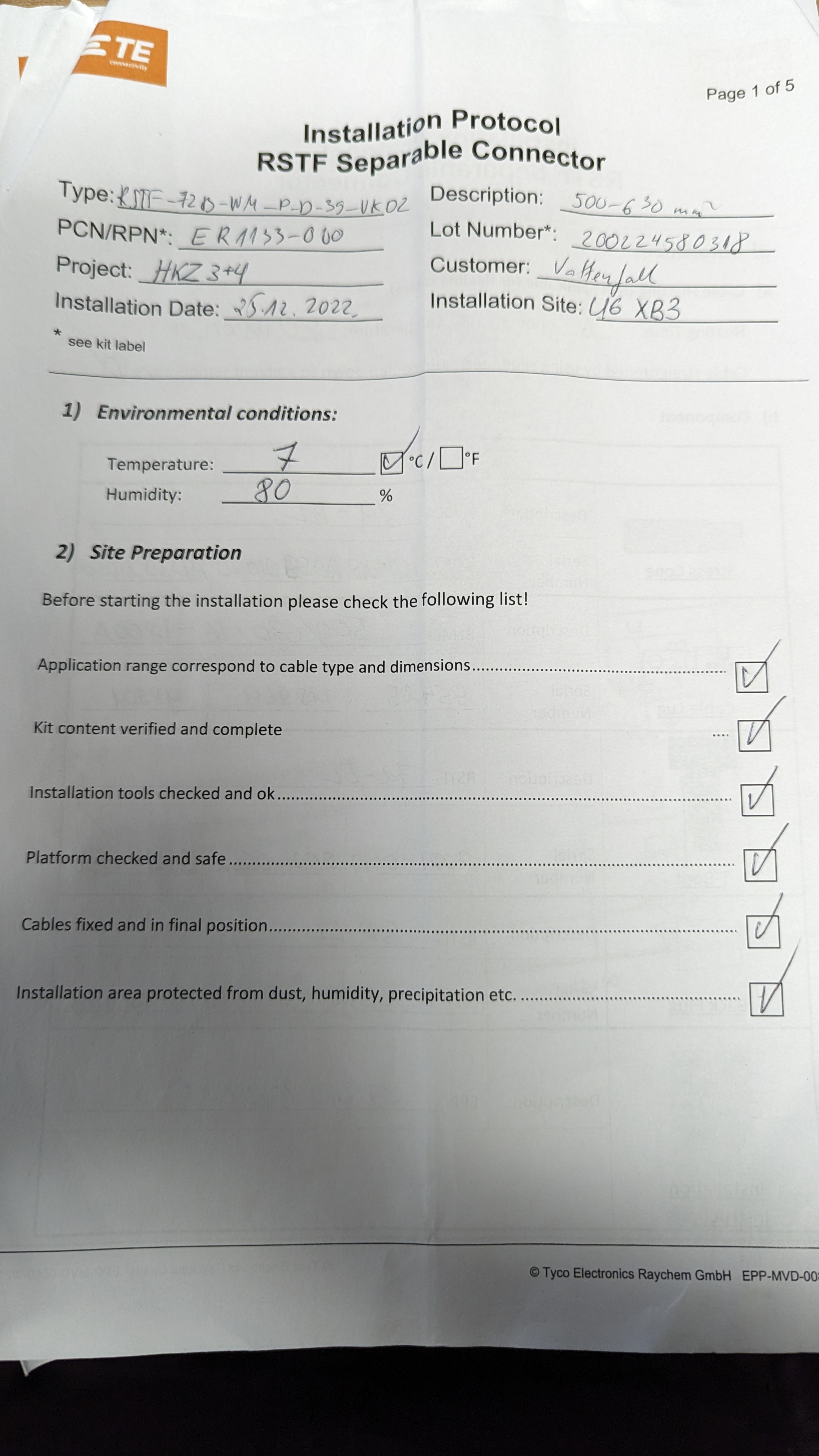
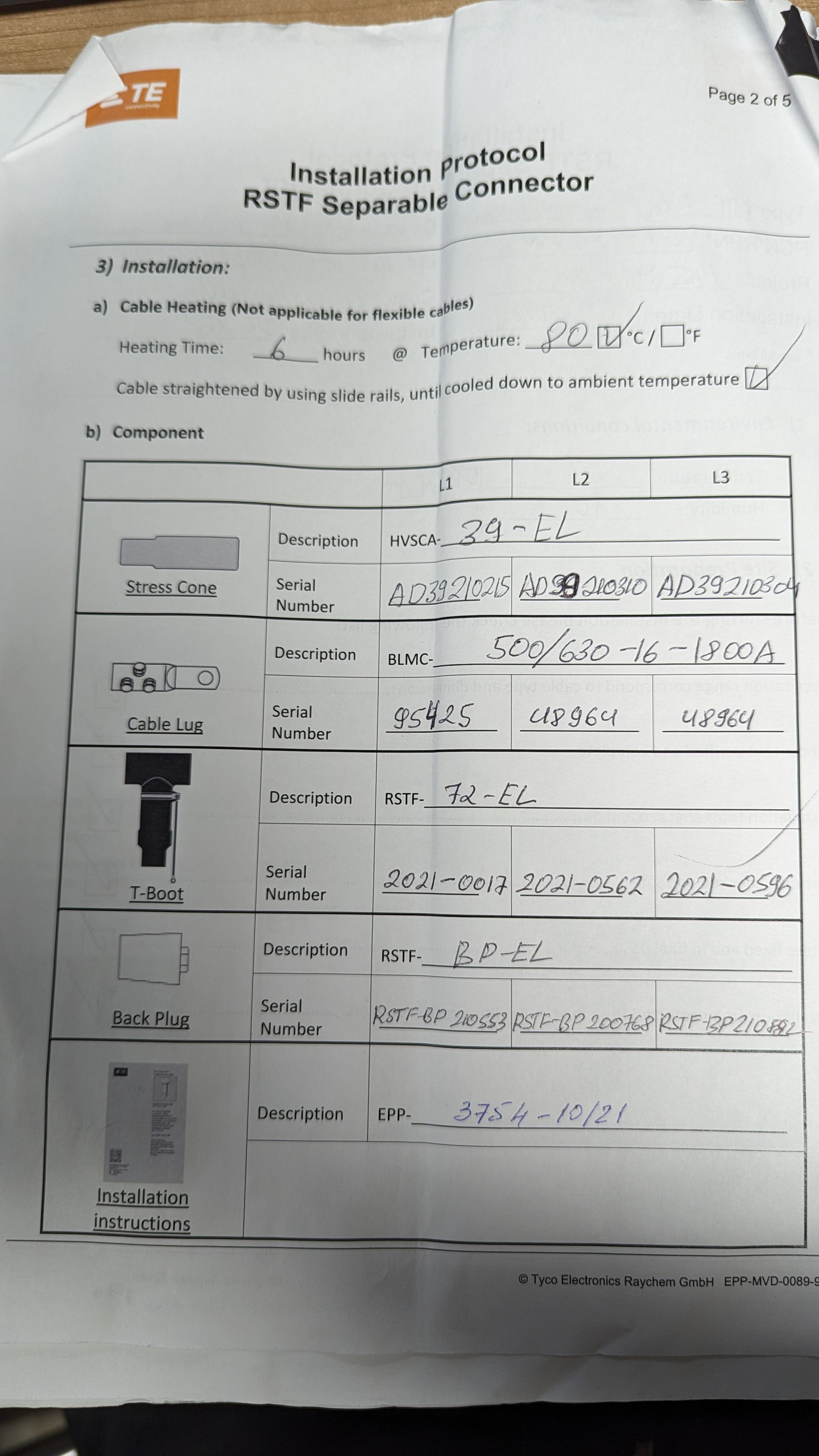
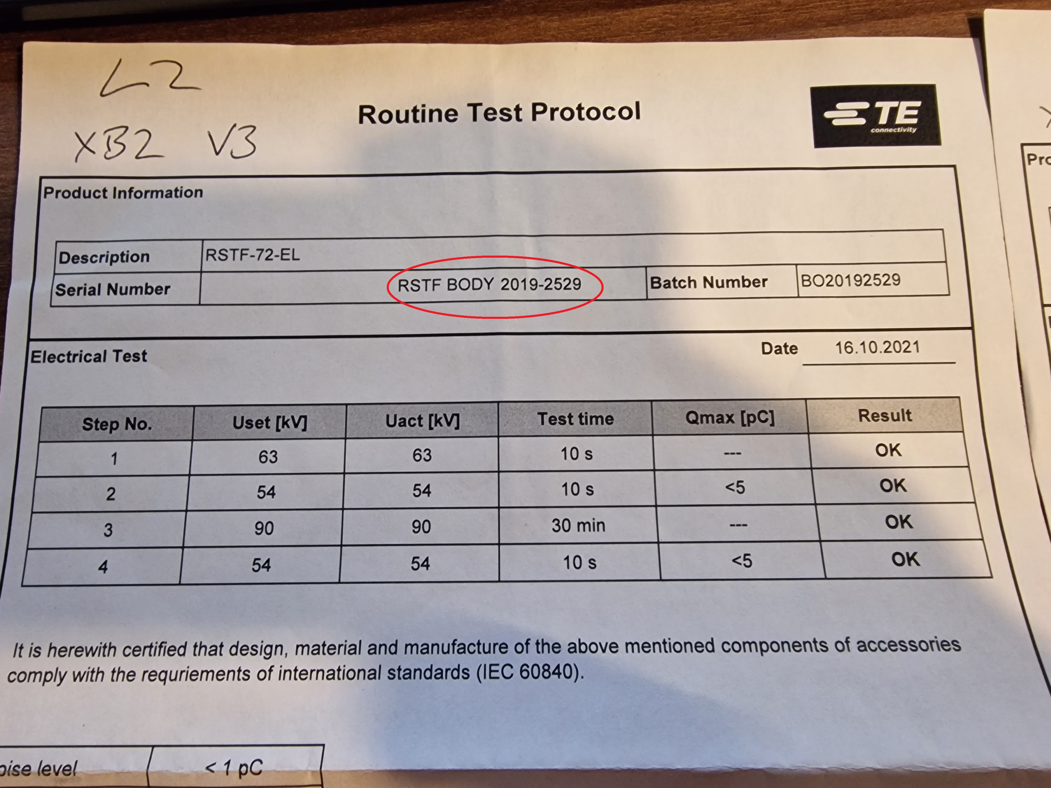
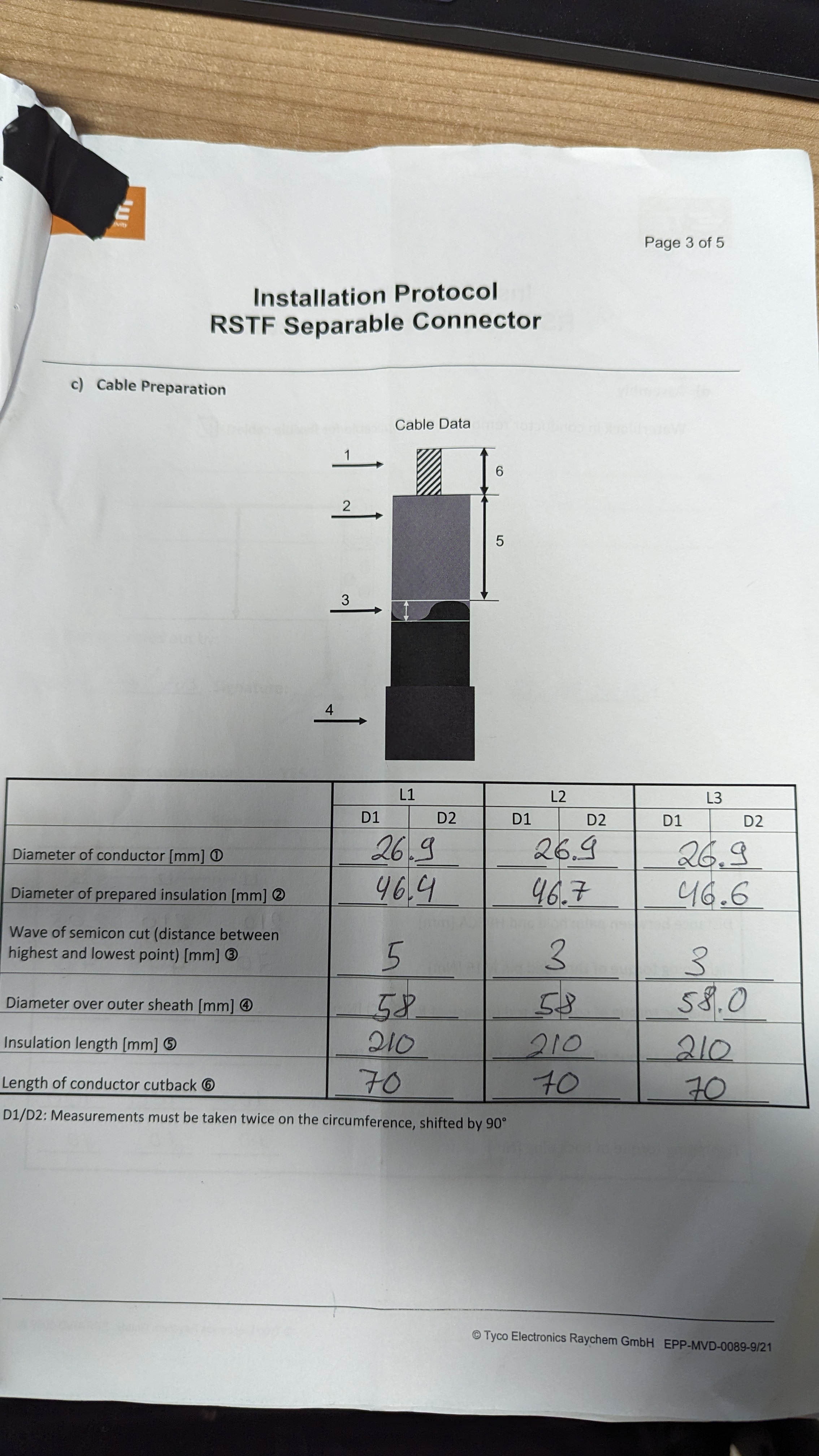
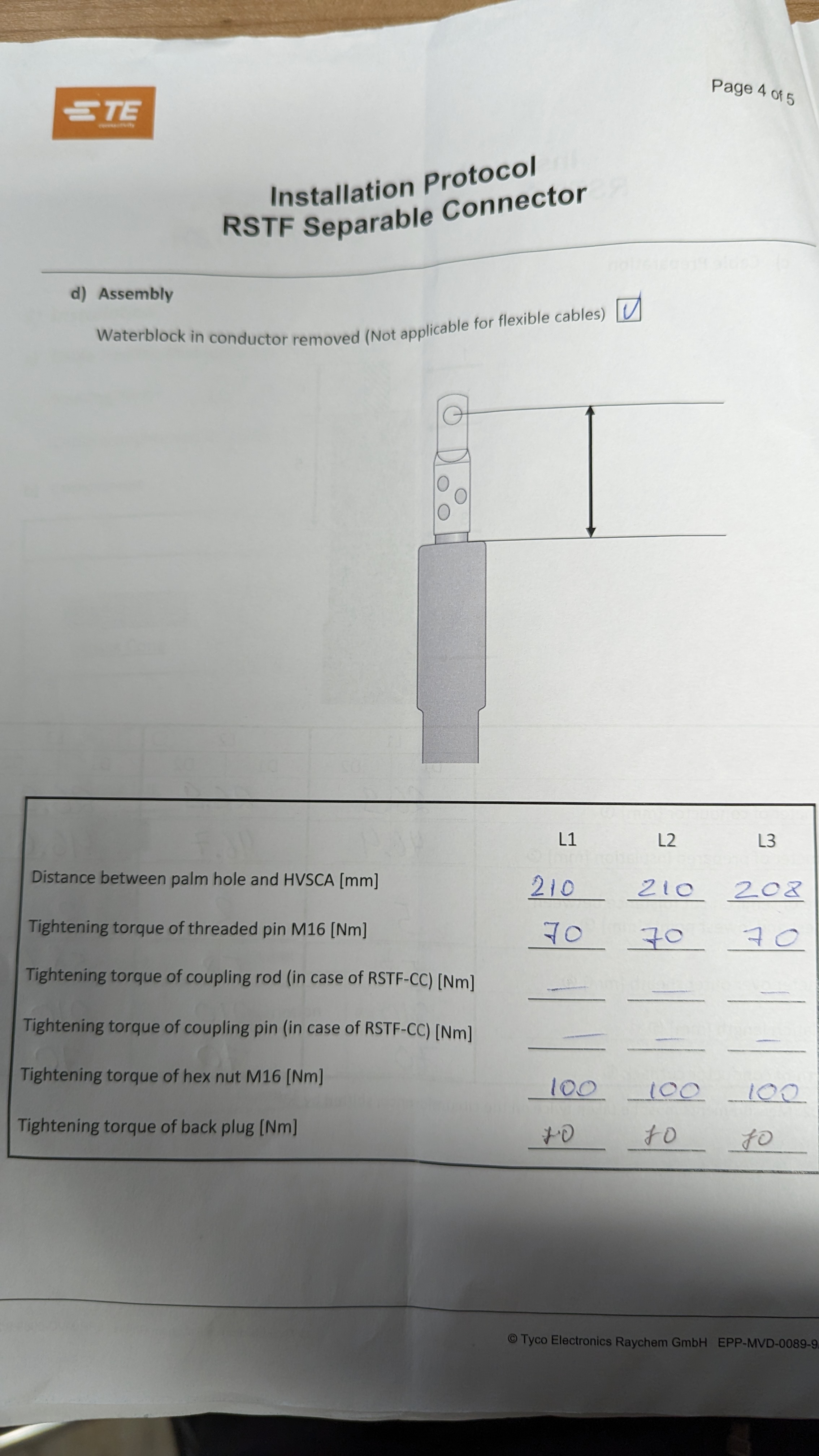
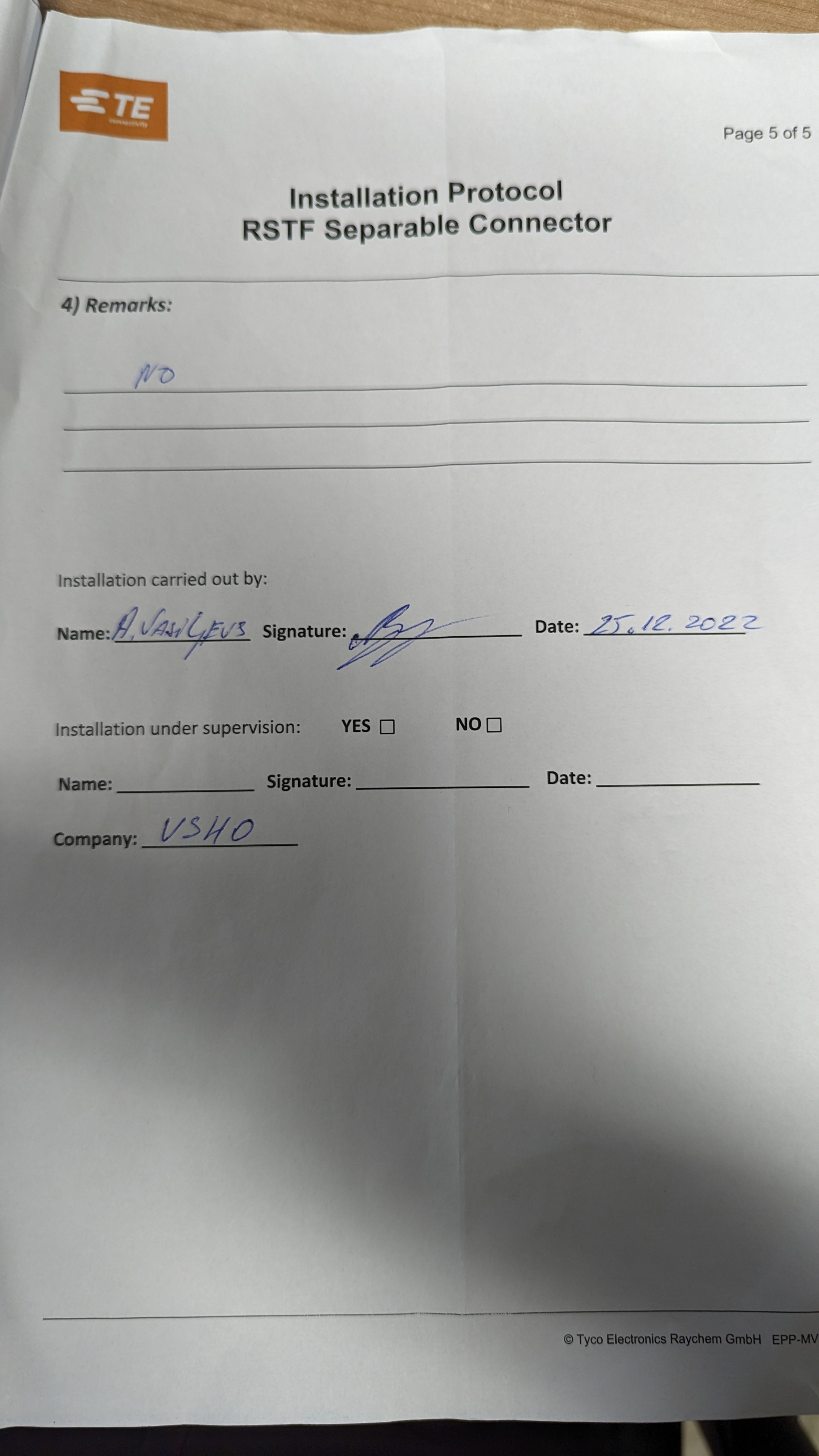
Ensure TE Documentation is filled out see example below
-
Ensure TE Documentation is filled out see example below
-
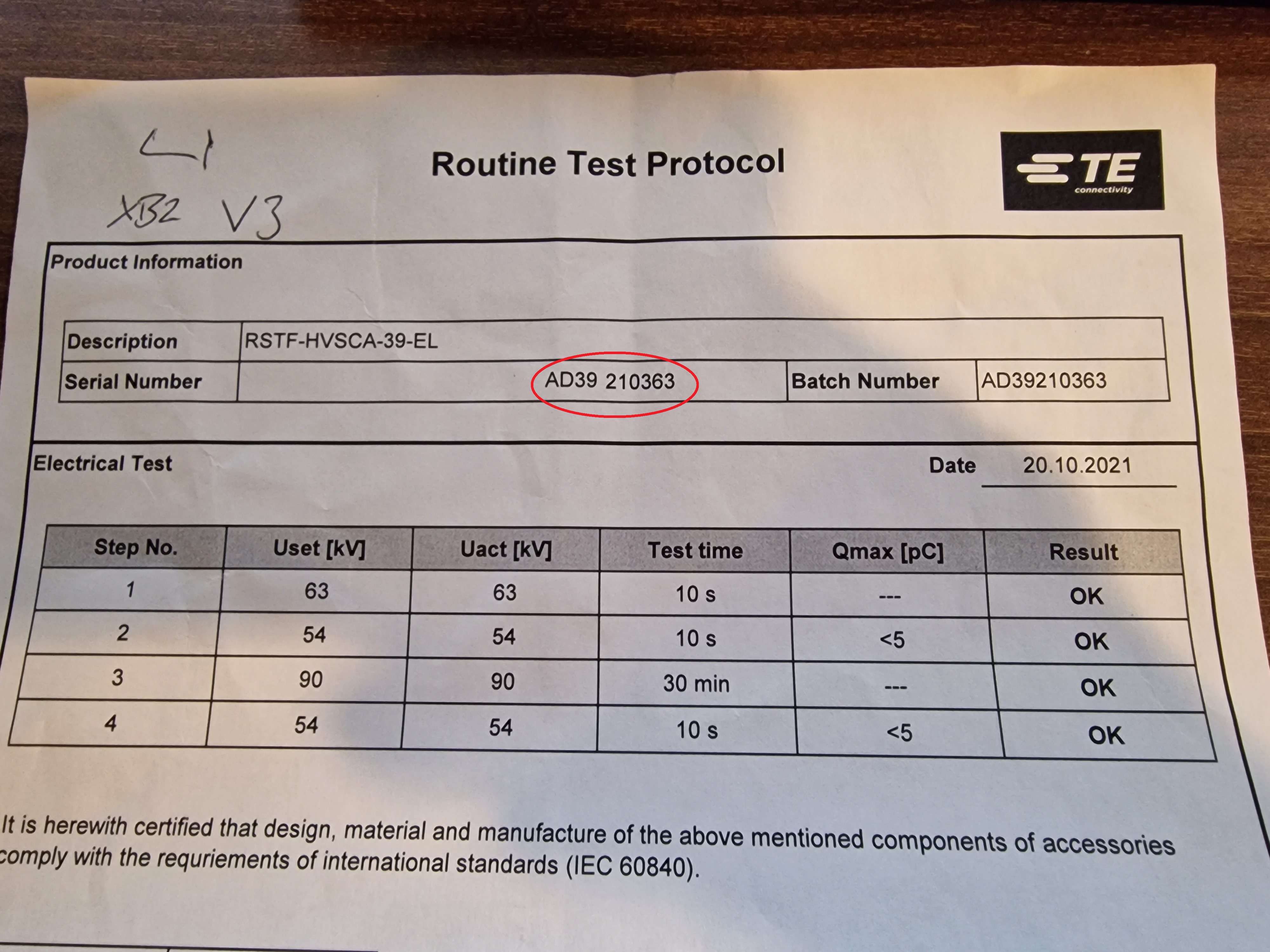
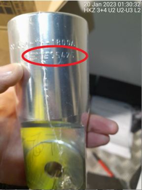
Stress cone serial number
-
L1 Stress cone
-
L1 Stress cone serial number
-
L2 Stress cone
-
L2 Stress cone serial number
-
L3 Stress cone
-
L3 Stress cone serial number
-
Cable Lug Serial Number
-
L1 Cable Lug
-
L1 Cable Lug serial number
-
L2 Cable Lug
-
L2 Cable Lug serial number
-
L3 Cable Lug
-
L3 Cable Lug serial number
-
T-Boot Serial Number
-
L1 T-Boot
-
L1 T-Boot serial number
-
L2 T-Boot
-
L2 T-Boot serial number
-
L3 T-Boot
-
L3 T-Boot serial number
-
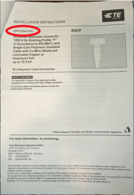
Jointing instructions EPP
-
Picture showing jointing instruction EPP
-
Jointing Instruction EPP serial number
HV Terms/Cable Preperation
-
Ensure that the cable and switchgear are disconnected from any voltage source and earthed.
-
Check for a Valid E-Permit with isolation measures detailed
-
Ensure you leave enough length for earth screens
-
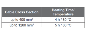
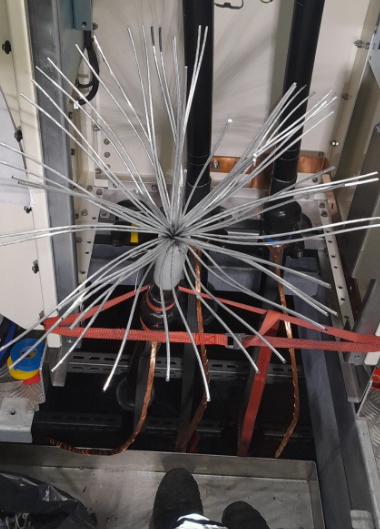
Heat/Straighten Cables ensure cable is allowed cooling after removing blankets
-
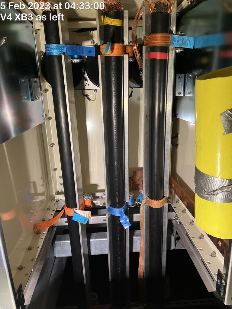
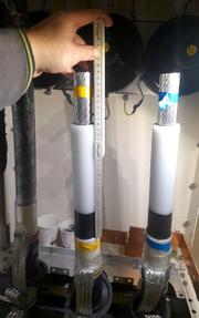
Example picture showing bars installed ensure you have extra length for screens
-
Picture Showing the Bars installed after heating
-
Length of time cables heated for
-
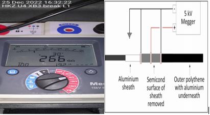
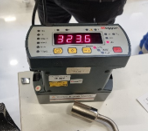
MOC-TT-007 Break Test diagram for reference 5KV for 1min (Picture required showing megger display showing result over 100MΩ)
-
L1 Picture showing Megger display proving no breakdown result over 100MΩ
-
L2 Picture showing Megger display proving no breakdown result over 100MΩ
-
L3 Picture showing Megger display proving no breakdown result over 100MΩ
-
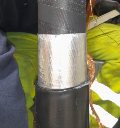
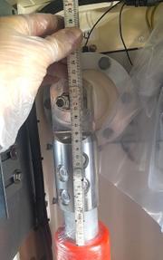
Take 4 pictures off the window showing all angles
-
L1 Clean Window 4 pictures off the window showing all angles
-
L1 Window measurement
-
L2 Clean Window 4 pictures off the window showing all angles
-
L2 Window measurement
-
L3 Clean Window 4 pictures off the window showing all angles
-
L3 Window measurement
-
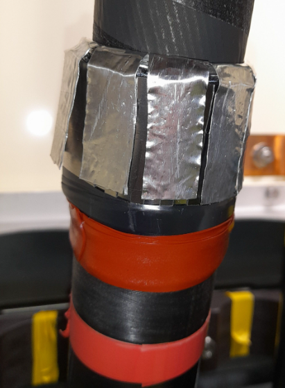
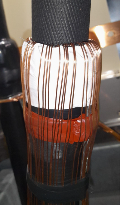
Take Pictures of the Ali Foil bend over the support ring as shown
-
L1 Ali Foil Bend over support ring
-
L2 Ali Foil Bend over support ring
-
L3 Ali Foil Bend over support ring
-
Take Pictures Before tape is applied
-
L1 Before Tape on window
-
L2 Before Tape on window
-
L3 Before Tape on window
-
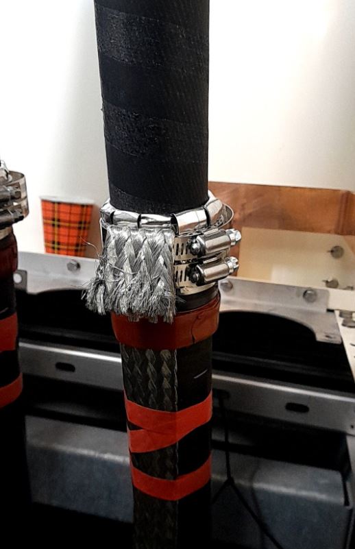
Picture showing CR display off contact resistance between window and braid
-
L1 CR Display off contact resistance
-
L1 CR measurement
-
L2 CR Display off contact resistance
-
L2 CR measurement
-
L3 CR Display off contact resistance
-
L3 CR measurement
-
Take Pictures After Tape is applied and screens are down
-
L1 After tape is applied and screens are down
-
L2 After tape is applied and screens are down
-
L3 After tape is applied and screens are down
-
Picture Showing the heatshrink installed from different angles
-
L1 After heatshrink install
-
L2 After heatshrink install
-
L3 After heatshrink install
-
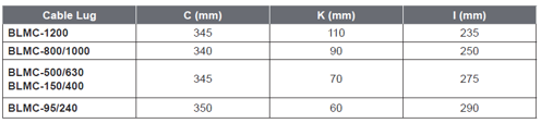
Table Showing measurements depending on cables sizes/Kits (Ensure Core is longer for removing waterblock)
-
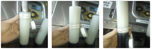
Picture Showing the core opened and clean see example below
-
L1 Core opened and clean
-
L2 Core opened and clean
-
L3 Core opened and clean
-
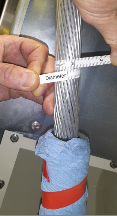
Picture showing the core back together see example below(Must be within 1mm off original Diameter)
-
L1 Core back together after clean
-
L2 Core back together after clean
-
L3 Core back together after clean
-
Picture showing the Diameter in 3 points as displayed in pictures below for each phase after sanding
-
L1 Showing 3 diameter measurements
-
L1 diameter measurement
-
L1 diameter point two measurement
-
L1 diameter point three measurement
-
L2 Showing 3 diameter measurements
-
L2 diameter measurement
-
L2 diameter point two measurement
-
L2 diameter point three measurement
-
L3 Showing 3 diameter measurements
-
L3 diameter measurement
-
L3 diameter point two measurement
-
L3 diameter point three measurement
-
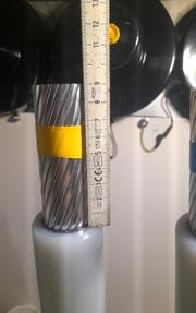
Picture Showing core length with a ruler see example below
-
L1 Core Length
-
L1 core length measurement
-
L2 Core Length
-
L2 core length measurement
-
L3 Core Length
-
L3 core length measurement
-
Picture Showing the whole length of the Prepared cable with a ruler see example below
-
L1 Whole prepared cable length
-
L1 full length measurement
-
L2 Whole prepared cable length
-
L2 full length measurement
-
L3 Whole prepared cable length
-
L3 full length measurement
-
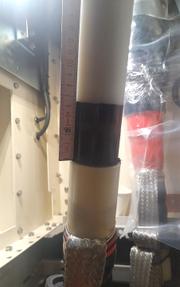
Picture Showing Transition with ruler against it see example below
-
L1 Showing Transition with ruler against it
-
L1 Transition measurement
-
L2 Showing Transition with ruler against it
-
L2 Transition measurement
-
L3 Showing Transition with ruler against it
-
L3 Transition measurement
-
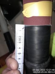
Picture of the transition wave with a ruler aginst it see example below showing lowest to highest point
-
L1 Showing Wave measurement
-
L1 Wave measurement
-
L2 Showing Wave measurement
-
L2 Wave measurement
-
L3 Showing Wave measurement
-
L3 Wave measurement
-
Ensure TE Documentation is also filled out
-
Confirm TE Documentation is completed up to required stage
-
Picture Showing the bushing before T-Boots installed with threads installed (The thread should be installed hand tight as far as possible)
-
The thread should be installed hand tight as far as possible in final position then torqued (Please report this to the HV Supervisor if not)
-
Confirm Thread torqued to 70NM
-
All Three bushing shown clearly before T-Boots installed
-
Picture Showing the lug installed with ruler against it see example below
-
L1 Lug Measurement after install
-
L1 lug to stress cone measurement
-
L2 Lug Measurement after install
-
L2 lug to stress cone measurement
-
L3 Lug Measurement after install
-
L3 lug to stress cone measurement
-
Confirm T-Boots torqued to 100NM
-
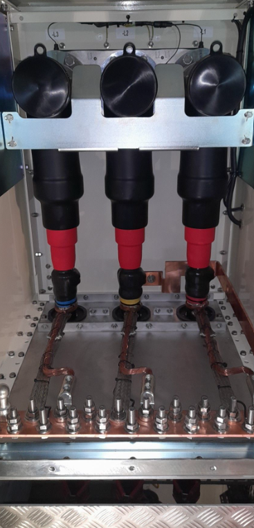
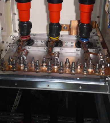
Picture stepped back showing insulation plugs installed when all 3 are installed
-
Picture stepped back showing insulation plugs installed when all 3 are installed
-
Confirm Back Plugs torqued to 70NM
-
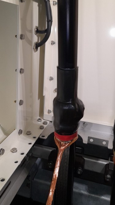
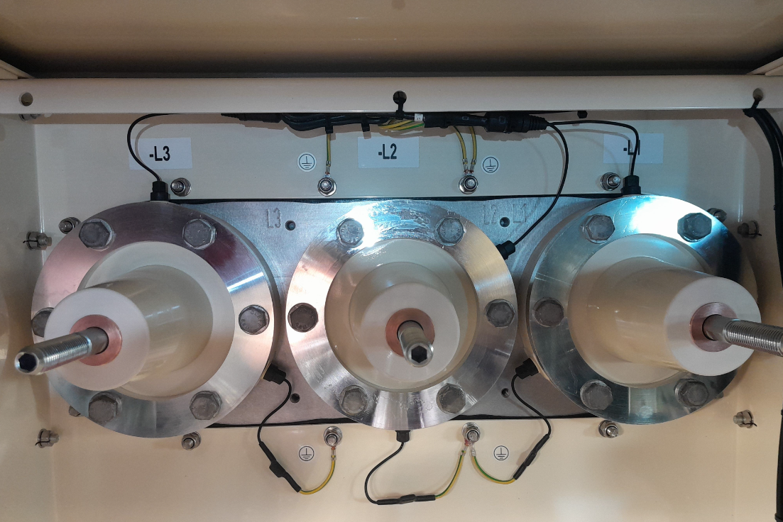
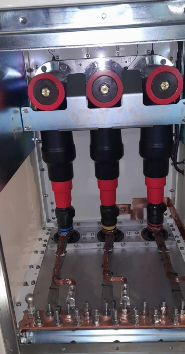
Picture Showing the T-Boot installed completed/Cabinet Complete see example below
-
Picture Showing All T-Boots installed
-
Ensure TE Documentation is also filled out
-
Confirm TE Documentation is completed
-
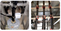
Picture Showing Earths installed see example below
-
Picture showing completed Earths
-
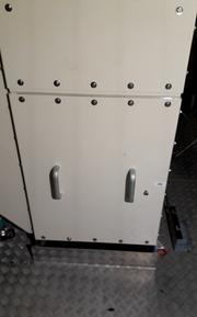
Picture showing closed switchgear door see example below
-
Picture of the Switchgear Closed
-
Picture Showing installed labels above the hang-off and under the switchgear see examples off the required pictures below
-
X2 Pictures Showing labels above the Hang-Off and also below the switchgear
-
Ensure TE Documentation is filled out and signed
-
Confirm TE Documentation is fully completed (Hand the completed document to HV Supervisor)
-
Pictures showing all of the pages from the TE documentation completed

Sign Off
-
I Can confirm the termination has been executed according to NS2244-ENG-0024 Cable Termination Power Cores FOU Procedure.
-
Client Rep Present
-
Client Rep Signature
-
V&SH Tower team Lead (Add notes if full termination wasn't done by one jointer showing which points where done)
-
SOC HV Supervisor to review and confirm installation work carried out satisfactory meeting the specified requirements and tick complete.
-
SOC HV Supervsior
-
Comment if applicable


 - duplicate")


 - duplicate")
 - duplicate")
 - duplicate")