


Title Page
-
Site conducted
-
Conducted on
-
Location
-
Cable ID
-
Prepared by
-
Tick
Sub-Task #1 Preparation
-
Status of installation: both ends of the cable are fully terminated, a test team is available on both structures.
-
Perform Toolbox talk
-
Toolbox Talk
Check for a valid permit to work (PTW) and review required safety measures
• For the OSS ensure to apply and obtain PTW from TenneT and Petrofac system.
• For FOU ensure to apply and obtain PTW from Vattenfall
Attached TRA M-00011431 -
This task plan covers both locations (both cable ends) and both types of structures (MP and OSS). End A is equipped with the test equipment and is leading the operations, Remote end / End B is assisting from the far end of the cable.
-
Verify your location, the cable ID, cable route and switchgear location and ID.
-
Check in over the radio with the transfer vessel and neighbouring teams so that everybody is aware of ongoing works.
-
Check that all tools and test equipment required for the work is available and in good condition, and calibration is still valid.
-
Check cable ends are secured and safe and that if any personnel are present, they are authorised to be so and where applicable safety warning notices are fixed to warn that the cable is under test.
-
Establish and test reliable two-way radio communication between cable test end and if applicable personnel present at the remote non-test end.
-
1.9 Ensure that the cable is disconnected from any voltage source and is earthed. Check for a valid Permit to Work / Sanction for Test.
-
Gain access to the cable ends.<br>WTG: open the cable compartment of the switchgear from the side. Unscrew the bolts ad remove the compartment cover according to the manual.


Sub-Task #2 Phase ID
-
This test requires a team at the remote end.<br>Make radio contact.
-
The power cores phases where individually identified following the pre-termination test and have the following manufacturing markings:
• TKF – Meter and phase marking is applied to the outer sheath
• Prysmian – Under the screen, core marking is done with a coloured identification tape. -
End A&B: Identify the cable under test at both the test end and the remote ends based on the cable RDSPP identification labels.
-
End A&B: Disconnect the power screen connections from the earth bar.
-
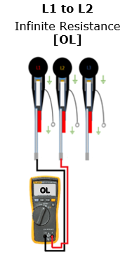
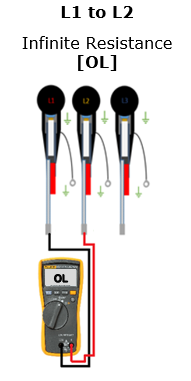
End A&B: Perform phase ID to verify the cable core identified as ‘L1’
-
End B: Link together the screen earths ‘L2’ and ‘L3’.
-
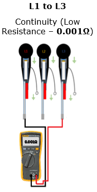
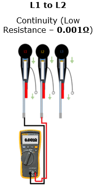
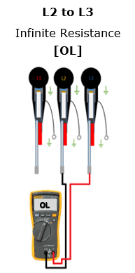
End A: Connect the fluke between ‘L1>L2’, ‘L1>L3’ & ‘L2>L3’ ensuring the reading are as follows:
-
-
-
-
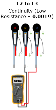
End A&B: Perform phase ID to verify the cable core identified as ‘L2’
-
End B: Link together the screen earths ‘L1’ and ‘L3’.
-
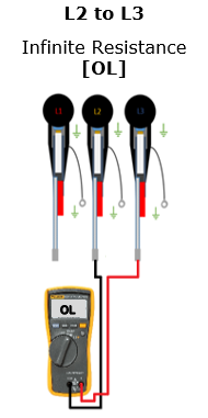
End A: Connect the fluke between ‘L1>L2’, ‘L1>L3’ & ‘L2>L3’ ensuring the reading are as follows:
-
-
-
-
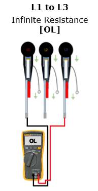
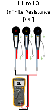
End A&B: Perform phase ID to verify the cable core identified as ‘L3’
-
End B: Link together the screen earths ‘L1’ and ‘L2’.
-
End A: Connect the fluke between ‘L1>L2’, ‘L1>L3’ & ‘L2>L3’ ensuring the reading are as follows:
-
-
-
-
End A&B: Proceed to Step 3 TDR Testing.

Sub-Task #3 TDR Testing
-
Make a note of the cable length recorded at Pre-Termination Testing.
-
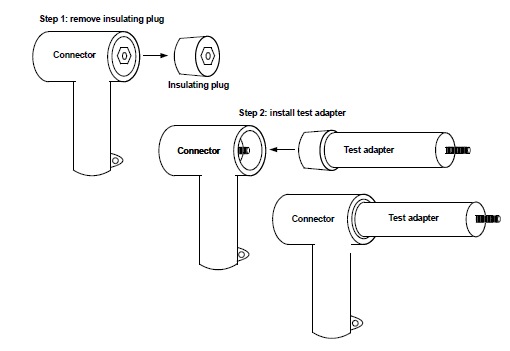
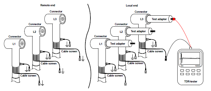
Where applicable install the test adaptors onto the power cores.
-
-
Connect the red wire of the TDR-tester to the test adapter positive terminal and the black wire to the earthed metallic screen.
-
-
Configure TDR unit with correct parameters for cable under test including Pulse Width, Distance Range according to cable data sheet.
-
The Propagation Velocity (V/2) during SAT was:
• TKF 84.3 to 86.1 m/µs
• Prysmian 79.3 to 80 m/µs -
The acceptance criteria shall be:
• No unexplained events recorded between any conductors i.e. the trace shall be smooth and flat. -
Carry out TDR Testing.
-
Verify Pass / Fail Thresholds - No unexplained events recorded between any conductors i.e. the trace shall be smooth and flat.
-
Confirm the length displayed on the test equipment is the same value recorded at Step 3.1 minus any cable cut during the assembly of the termination.
-
Take photos showing the TDR Trace displayed for each phase (L1, L2 & L3 - three (3) Photos).
-
Ensure the trace is saved and appropriately stored on the TDR Test Equipment.
-
Remove the test equipment from the power core under test
-
Repeat Steps 3.3 through to and including Step 3.13 for each power core until all selected power cores are tested and results verified.
-
End A&B: Reconnect the power screen connection to the earth bar.


Sub-Task #4 Conductor Resistance
-
DC Cable Resistance Testing will be carried out using either the switchgear circuit earth (core to core) or the power core screen (screen to core) as the ‘shorting’ link when measuring the power core resistance.
-
Obtain and make a note of the mean sea temperature.
-
Make note of the TDR length – [Total Measured Length].
-
Is the test being carried out Core to Core
-
Is this Task Plan assigned to End A
-
Ensure the cable lug is fitted and not connected to the switchgear bushing.
-
Configure the CR Test Unit
-
Carry out a CR test between cores L1 & L2 and record the reading displayed on the digital readout [Total Measured Resistance].
-
Take a picture of the digital readout on the CR Test Unit
-
Repeat testing cores L1 & L3
-
Repeat testing cores L2 & L3
-
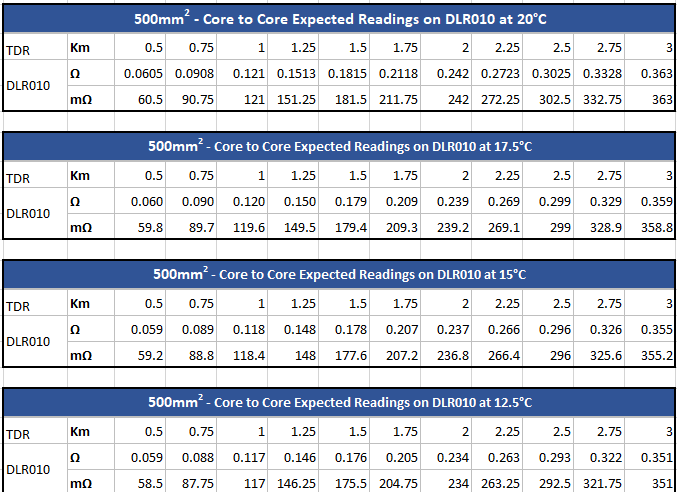
Evaluate the readings ensuring the three values resemble the values given in the core to core table for the given cable length and sea temperature.
-
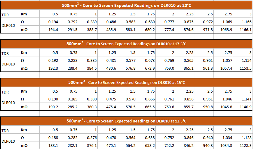
Expected measurement to be displayed on the DLR010 when testing Core to Core
-
Is this Task Plan assigned to End B
-
Power core shall be connected to the bushing and switchgear earth is closed
-
Is the test being carried out core to screen
-
Is this Task Plan assigned to End A
-
Ensure the cable screen is disconnected, the insulation plug is removed and the termination stud is accessible (either on or off the switchgear bushing).
-
Identify the first core to test L1 - confirm with the remote end (End B) that a loopback has been formed between the power core screen and the termination stud has been made.
-
Core L1 - carry out a resistance test between the power core screen and the termination stud and record the reading displayed on the digital readout [Total Measured Resistance].
-
Take a picture of the digital readout on the CR Test Unit
-
Repeat for Core L2
-
Repeat for Core L3
-
Evaluate the readings ensuring the three values resemble the values given in the core to screen table for the given cable length and sea temperature.
-
Expected measurement to be displayed on the DLR010 when testing Core to Screen
-
Is this Task Plan assigned to End B [Remote End]
-
Ensure the cable screen is disconnected, the insulation plug is removed and the termination stud is accessible (either on or off the switchgear bushing).
-
-
Identify core L1, and form a loopback by connecting the power core screen to the termination stud.
-
Repeat for Core L2 & L3
Sub-Task #5 Contact Resistance Test
-
The contact resistance of the following earthing connections shall be measured using a calibrated digital micro‐ohmmeter.
• Fibre optic cable armour, metal tube and box to earth bar
• Power core screen to switchgear earth bar.
• Hang-off earth to hang-off flange earth boss
• Cable Containment/cleats to MP (internal platform) / WTG tower earthing point. -
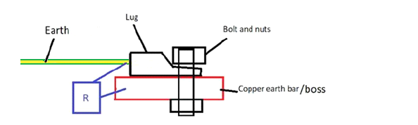
Visually verify that lug of the earth cable is correctly connected at the correct earthing point.
-
-
Acceptance criteria shall be:<br> • Cable Containment ≤0.5mΩ<br> • FO Gland ≤0.5mΩ<br> • FO Enclosure ≤0.5mΩ<br> • Screen to Earth Bar ≤0.5mΩ<br> • FO Metal Tube ≤0.9mΩ<br> • Hang Off Earth ≤0.9mΩ
-
Carry out a contact resistance of the fibre optic box earth connections and take photos of the digital display ensuring the reading is less than 0.5mΩ - [Photo 1: Connection at Box] + [Photo 2 - Connection at Hang Off Earth Bar].
-
Take two photos showing the digital readout when testing the FO Box contact resistance - [Photo 1: Connection at Box] + [Photo 2 - Connection at Hang Off Earth Bar].
-
Carry out a contact resistance of the fibre optic steel tube earth connections and take photos of the digital display ensuring the reading is less than 0.9mΩ.
-
Take one photo showing the digital readout when testing the FO Steel Tube contact resistance - [Photo 1: Steel Tube to Earth]
-
Carry out contact resistance of the Hang Off earth connections and take x2 photos of the digital display ensuring the reading is less than 0.9mΩ - [Photo 1: Bottom Plate Earth Cable Lug to Top Plate Earth Cable Lug] + [Photo 2 - Top Plate Earth Cable Lug to Hang Off Earth Bar].
-
Take two (2) photos showing the digital readout when testing the Hang Off contact resistance - [Photo 1: Bottom Plate Earth Cable Lug to Top Plate Earth Cable Lug] + [Photo 2 - Top Plate Earth Cable Lug to Hang Off Earth Bar].
-
Carry out contact resistance of the cable containment earth connections and take x1 photo of the digital display ensuring the reading is less than 0.5mΩ - [Photo 1: Containment to Hang Off Earth Bar].
-
Take one (1) photo showing the digital readout when testing the Cable Containment contact resistance - [Photo 1: Containment to Hang Off Earth Bar].
-
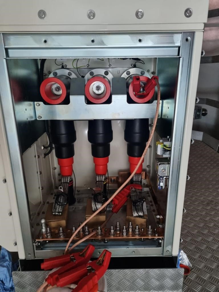
Carry out contact resistance of the power core screens, connector drain earth and the switchgear earth bar taking seven (7) photos of the digital display ensuring the reading is less than 0.5mΩ - [Photo 1-3: Braids to Earth] + [Photo 4-6 - Connector Drains to Earth] + [Photo 7: Earth Bar to Earth Bar].
-
Take seven (7) photos showing the digital display when testing the power core screens: [Photo 1-3: Braids to Earth] + [Photo 4-6 - Connector Drains to Earth] + [Photo 7: Earth Bar to Earth Bar].
Sub-Task #6 Completion
-
Are you performing this Sub-Task
-
8.1 Normalize FO Box / or Patch panel.
-
8.2 Close and normalize HV switchgear in WTG tower and OSS.
-
8.3 Take pictures of the as left situation on WTG and OSS.
-
8.4 Close hatches/doors.
-
8.5 Close Sanction for Test.
-
8.6 Collect all tools and waste. Prepare them for lifting off the tower. Clean any stains caused
-
8.7 Lift off equipment by the crane of the ISV (if no other works to be done).
-
8.8 Leave Structure.
Sign off
-
Client present?
-
No Client present
-
Client Representative
-
Comment if applicable
-
V&SH Tower Team Lead
-
SOC HV Supervisor to review and confirm installation work carried out satisfactory meeting the specified requirements and tick complete.
-
SOC HV Supervisor
-
Comment if applicable


 - Updated 8/14 - duplicate")


 - duplicate")
 - duplicate")
 - duplicate")

 - duplicate")
 - duplicate")

