 - duplicate")


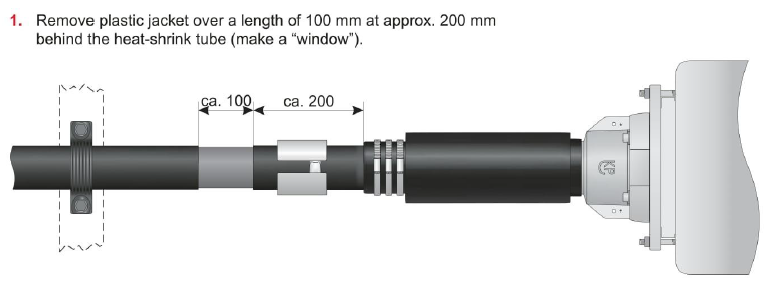
Title Page
-
Site conducted
-
Project: Hollandse Kust Zuid
Task Plan: NS2244-ENG-00026-ATT01
Procedure: NS2244-ENG-00026 Cable Termination Power Cores OSS
Rev: 1 -
Conducted on
-
Location ID
-
Cable type
-
String
-
Foundation
-
Cable ID
-
Prepared by
General Info and Task Objectives
-
Task Summary
1) Inter-array power cores termination in OSS Alpha
2) Completion of power cores final single cleating below the GIS -
Operational Limitations
- Weather limitations as per adverse weather procedure.
- A Safe System of Work is provided, the switchgear is in the earth position, locked to prevent
operation and appropriate warning notices displayed.
- The inter-array cable second end on the first FOU is terminated first. -
Initial Status
- Status of installation: The power cores are routed and fastened to the structure with cable
cleats.
- The cable ends are available for termination on a suitable working level (e.g. mobile
scaffolding)
- Pre-termination testing is completed.
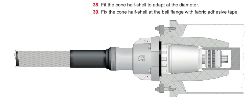
Sub Task # 1) Preparation
-
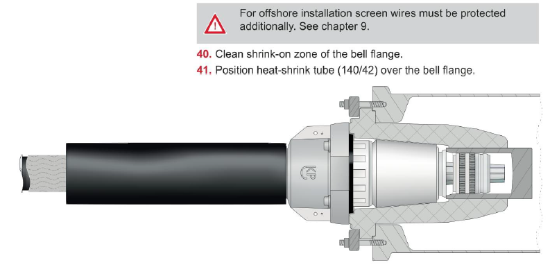
Are you performing this Sub-Task?
-
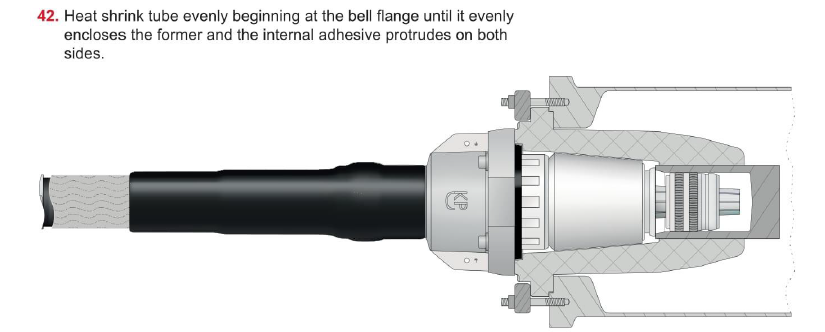
1.1 Perform Introduction and Toolbox talk with all involved personnel
-
Check for a valid permit and review required safety measures.
Note: Specific topics to be addressed in the Permit to Work are
as a minimum:
- Electrical work, including HV testing,
- Hot work. -
1.2 Perform Radio communication check with the offshore vessel (ISV / CTV)
-
1.3 Lift tools from the offshore vessel (ISV / CTV) to OSS.
-
1.4 Verify your location, the cable ID, cable route and switchgear location and ID.
-
1.5 Ensure that the cable and switchgear are disconnected from any voltage source and are earthed.
-
Check for a valid Permit to Work with isolation measures.
-
1.6 Check that all cable fixing material (cable cleats) and termination kits are provided and suitable for the installation (matching the cable size).<br>Check that all tools required for the work is available, in good condition and where applicable hold valid calibration certification.
-
1.7 Wrap sharp edges with rubber of foam to prevent damages to the cable.<br>(i.e. switchgear openings and close-by cable racking).
-
1.8 Check the accessible sections of the subsea power cores for outer sheath damages visually and with pulling the hands over the surface. Any repairs necessary shall be performed before termination.
-
1.9 Mobile scaffolding is assembled. Make sure that the scaffolding is earthed before starting any works on it. Then enter/access the scaffolding.
-
1.10 Check (continuously before/during/after cable handling) that the cable is handled and placed (permanent position) with the MBR taken into account. The use of (wooden) half circle template is recommended.


Sub Task # 2) Termination Preparation (TKF Cable)
-
Are you performing this Sub-Task?
-
2.1 The power cores phases are individually marked as follows:
-
- TKF – Meter and phase marking is applied to the outer sheath.
- Prysmian – Under the screen, core marking is done with a coloured identification tape. -
2.2 Confirm the correct phase order, which is for every cable in the switchgears left-to-right L3, L2 and L1.
-
2.3 Open the Roxtec sealing plates below the switchgear cable compartment.
-
2.4 INFORMATION: – Steps 2.5 to 2.9 below marking the so called “Jacket Cut” can be achieved by lifting the power cores into position or alternatively leaving the power cores on the scaffolding and using a rope of flexible hose instead.
-
2.5 Lift the power core one by one to the final position and fix them temporarily with slings or cargo straps or place them directly into the cable cleats.<br>Use the pad eyes and vertical cable support brackets to lift the cable core up from the scaffold to the switchgear bay using ratchet straps and/or lever hoist.<br>Arrange the cores below the switchgear according to phase sequence, so that the spreading out of the cores will be the easiest.<br>Minimum bending radius for single power cores:<br>- TKF 800mm 1.10m<br>- PRY 800mm 1.04m<br>Minimum bending radius has to be maintained at all times.
-
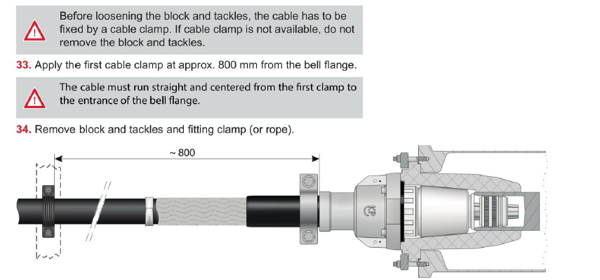
2.6 Adjust the cables that they come out of the last cleat straight and they reach the GIS straight to avoid mechanical tension on the end connectors.<br>- 1st cleat from GIS, (i.e. 800mm from Connex bell flange)<br>- 2nd cleat below Roxtec distance.<br>- For the 1st cleat from GIS, additional Oglaend rack will be installed above the I-beams (below GIS) to reach the recommended distance of 800 mm from Connex bell flange to 1st cleat.
-
2.7 Check that phase sequence is correct and make the cut marks on the cable.
-
2.8 Measure the required cable length with bending the cable to position, or with the help of a rope of flexible hose.<br>Measure the required metallic screen length to be able to connect it to the earthing point. The additional cable length above this point can be cut.
-
2.9 Lower the cable back down on the scaffolding.
-
2.10 Refit the Roxtec plates removed at Step 2.3 above
-
2.11 Install the cable termination kits according to the installation instruction doc. No.: 34022-IIN-OF0260994.
-
2.12 Each step of the TKF Installation Manual, Doc No.: 34022-IINOF0260994 has been extracted and inserted below (Steps 2.14 through to and including Step 2.20.1).
-
2.13 Should there be any discrepancies the contents of the Manufacturers Installation Instructions shall prevail.
-
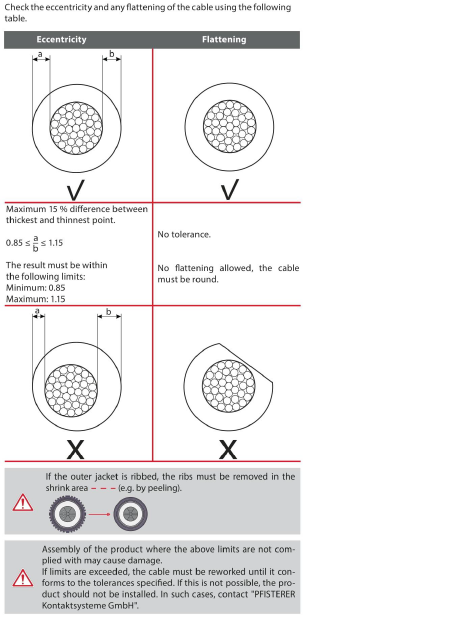
2.14 Cable Quality
-
Carry Out - Step 2.14.1
-
-
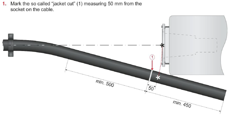
2.15 Cable Positioning, Heating, Straightening
-
Carry Out - Step 2.15.1
-
-
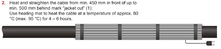
Carry Out - Step 2.15.2
-
-
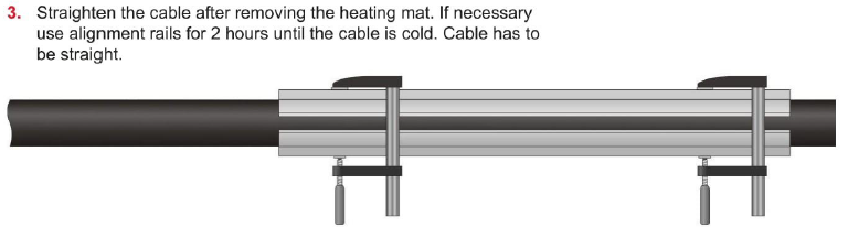
Carry Out - Step 2.15.3
-
-
Carry Out - Step 2.15.4
-
-
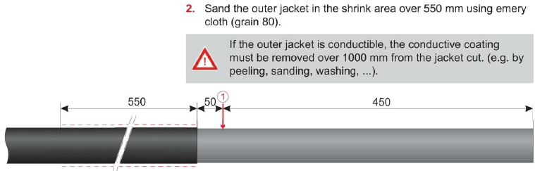
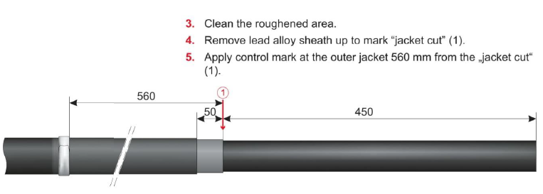
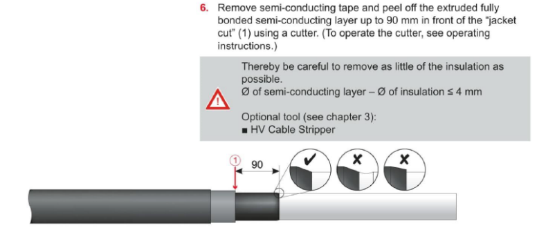
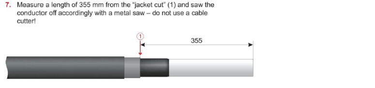
2.16 Cable Preparation
-
Carry Out - Step 2.16.1
-
-
Carry Out - Step 2.16.2
-
-
Carry Out - Step 2.16.3
-
-
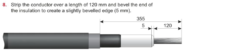
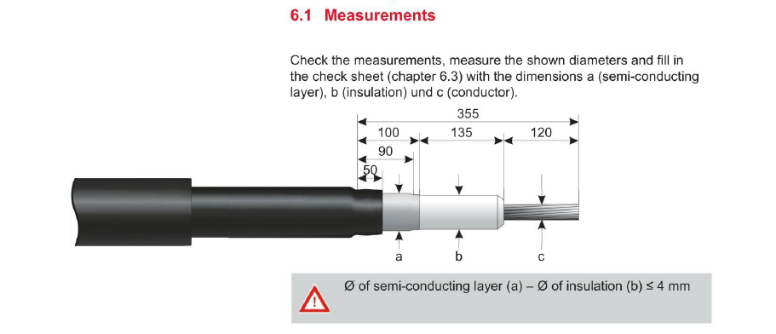
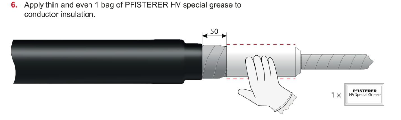
Step 2.16.4 - Photograph including date/time stamp and a ruler shall be taken showing the measurements of the prepared core.
-
Carry Out - Step 2.16.5
-
-
Carry Out - Step 2.16.6
-
-
Carry Out - Step 2.16.7
-
-
Step 2.16.8 - Photograph including date/time stamp shall be taken showing the bevelled edge.
-
Carry Out - Step 2.16.9
-
-
Carry Out - Step 2.16.10
-
-
Carry Out - Step 2.16.11
-
-
Carry Out - Step 2.16.12
-
-
Carry Out - Step 2.16.13
-
-
Carry Out - Step 2.16.14
-
-
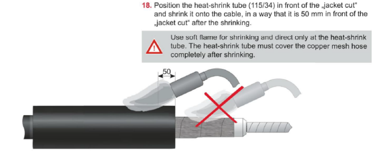
Step 2.16.15 - Photograph including date/time stamp and a ruler shall be taken showing the copper mesh hose.
-
Carry Out - Step 2.16.16
-
-
Carry Out - Step 2.16.17
-
-
Carry Out - Step 2.16.18
-
-
2.17 Checking
-
Carry Out - Step 2.17.1
-
-
Step 2.17.2 - Photograph including date/time stamp and a ruler shall be taken showing the prepared power cores.
-
Step 2.17.3 - Record the measurements in the Pfisterer Check Sheet - refer to Pfisterer Jointing Instruction, Step 6.3
-
Carry Out - Step 2.17.4
-
-
2.18 Assembly
-
Carry Out - Step 2.18.1
-
-
Carry Out - Step 2.18.2
-
-
Carry Out - Step 2.18.3
-
-
Carry Out - Step 2.18.4
-
-
Carry Out - Step 2.18.5
-
-
Step 2.18.6 - Photograph including date/time stamp and ruler shall be taken following the installation of the insulating part.
-
Carry Out - Step 2.18.7
-
-
Carry Out - Step 2.18.8
-
-
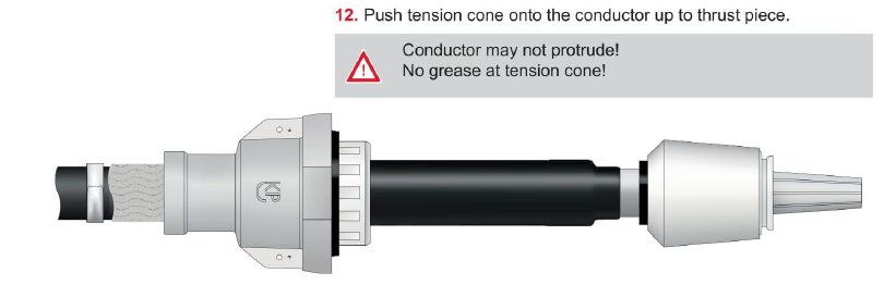
Step 2.18.9 - Photograph including date/time stamp shall be taken showing the tension cone fitted.
-
Carry Out - Step 2.18.10
-
-
Carry Out - Step 2.18.11
-
-
Carry Out - Step 2.18.12
-
-
Carry Out - Step 2.18.13
-
-
Carry Out - Step 2.18.14
-
-
Carry Out - Step 2.18.15
-
-
Carry Out - Step 2.18.16
-
-
Carry Out - Step 2.18.17
-
-
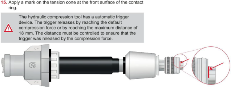
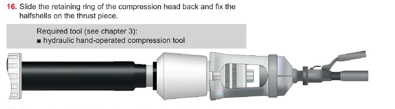
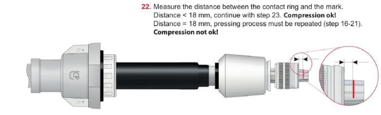
Step 2.18.18 - Photograph including date/time stamp and ruler shall be taken following the installation of the contact ring.
-
Carry Out - Step 2.18.19
-
-
Carry Out - Step 2.18.20
-
-
Step 2.18.21 - The following Steps Shall be completed after DAC Testing Proceed to Installing Temporary Test Connection Step 3
-
Step 2.18.22 - (This step might take place days/weeks after the steps above) Prepare bottom of the switchgear/remove Pfisterer Connex size 4 plugs and inspect the socket for any contamination or damages and make pictures.<br>Should this step not meet the requirements “ALL STOP” all assembly work shall stop and immediately report the identified contamination / damage to the Employer’s Representative.
-
Carry Out - Step 2.18.23
-
-
Step 2.18.24 - Photograph including date/time stamp shall be taken showing the internals of the socket.
-
Step 2.18.25 - Open the Roxtec sealing plates below the switchgear cable compartment
-
Carry Out - Step 2.18.26
-
-
Step 2.18.27 - When installing the power cores the protection cap shall remain fitted until the core is lifted through and clear of the penetration.
-
Step 2.18.28 - IAC cores to be protected during the plug-in operation to prevent any damages. MBR to be checked during and after final installation. No grinding work or open flame close to the live cables
-
Step 2.18.29 - Lift the cables one by one to plug them in and install them in the final position and place them directly into the cable cleats.<br>Use the pad eyes and vertical cable support brackets to lift the cable core up from the scaffold to the switchgear bay using ratchet straps and/or lever hoist.
-
Step 2.18.30 - Arrange the cores below the switchgear according to phase sequence, so that the spreading out of the cores will be the easiest. <br>Minimum bending radius of 1.10m SHALL be always maintained.
-
Step 2.18.31 - Adjust the cables that they come out of the first cleat straight and they reach the HV switchgear straight to avoid mechanical tension on the end connectors.
-
Carry Out - Step 2.18.32
-
-
Carry Out - Step 2.18.33
-
-
Carry Out - Step 2.18.34
-
-
Carry Out - Step 2.18.35
-
-
Carry Out - Step 2.18.36
-
-
Carry Out - Step 2.18.37
-
-
Carry Out - Step 2.18.38
-
-
Carry Out - Step 2.18.39
-
-
Carry Out - Step 2.18.40
-
-
Carry Out - Step 2.18.41
-
-
2.19 Earthing
-
Carry Out - Step 2.19.1
-
-
Step 2.19.2 - Photograph including date/time stamp and a ruler shall be taken showing the window cut from the outer sheath.
-
Carry Out - Step 2.19.3
-
-
Carry Out - Step 2.19.4
-
-
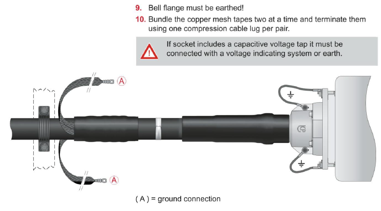
Step 2.19.5 - The contact resistance of the connection between the cable screen and the earthing braid shall be measured using a calibrated digital micro-ohmmeter.
-
Step 2.19.6 - Carry out a contact resistance check of the earthing connections and record the results
-
Step 2.19.7 - Photograph including date/time stamp shall be taken showing digital readout on the CR Test Unit.
-
Step 2.19.8 - Acceptance criteria shall be: ≤0.5mΩ
-
Carry Out - Step 2.19.9
-
-
Carry Out - Step 2.19.10
-
-
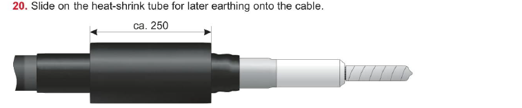
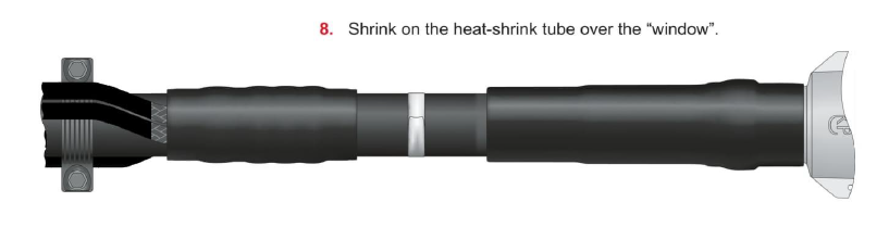
Step 2.19.11 - Photograph including date/time stamp shall be taken showing earthing arrangement prior to shrinking the heat shrink tube.
-
Carry Out - Step 2.19.12
-
-
Carry Out - Step 2.19.13
-
-
Step 2.19.14 - Photograph including date/time stamp shall be taken showing earthing arrangement after shrinking the heat shrink tube.
-
Step 2.19.15 - Photograph including date/time stamp shall be taken showing the earthed bell flange.
-
Step 2.19.16 - Photograph including date/time stamp shall be taken showing the straight cable between bell flange to the first cleat.
-
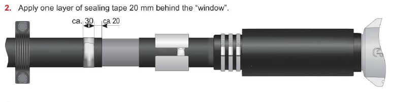
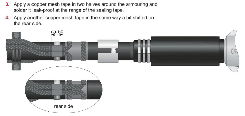
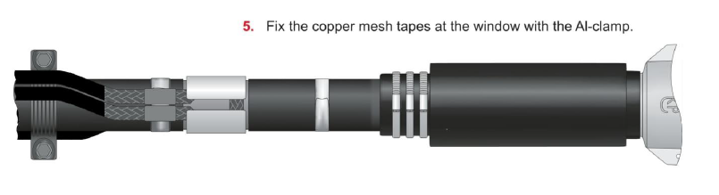
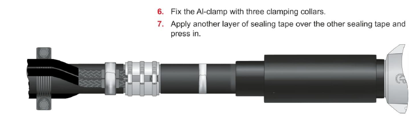
2.20 Sealing Set for Offshore Installation
-
Step 2.20.1
-
Step 2.21 - Refit the Roxtec plate.
-
Step 2.22 - Photograph including date/time stamp shall be taken showing the Roxtec Plate.
-
Step 2.23 - Connect the screen wires to the earth bar within the GIS Room.
-
Step 2.24 - Install cable identification labelling.
-
Step 2.25 - Finalize installation and double check that all bolts are tight and mark the torqued bolts with a marker. Check if the cable is sufficiently straight and there is no stress on the inner cone connectors.
-
Step 2.26 - Photograph including date/time stamp shall be taken showing the torqued and marked bolts.


Sub Task #3) Installing Temporary Testing Connection
-
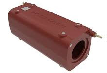
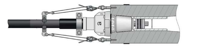
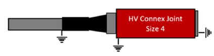
Step 3.1 - A Pfisterer joint block will be utilised as temporary testing connection point for the subsea power cores on the OSS
-
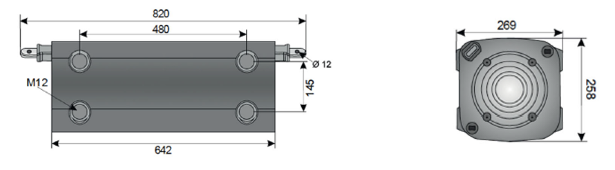
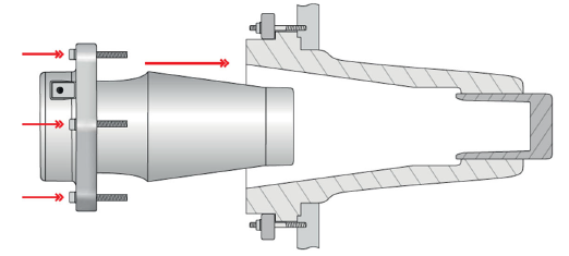
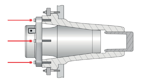
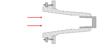
Carry Out Step 3.2 - The joint must be temporarily fixed on a framework or rack. The embedded threaded bushings M12 are provided for that purpose. The dimensions for fixing are equal to the following drawings
-
-
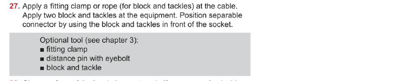
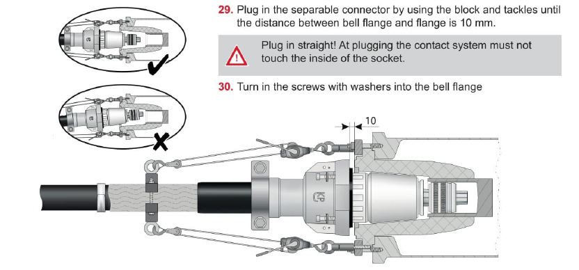
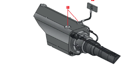
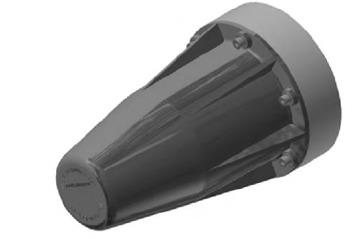
Carry Out Step 3.3 - The assembly of the cable connectors must be done according to installation instructions for cable connector size 4. Especially for the plug-in process and the greasing of the insulating part and the inner cone of the joint.<br>An insulated block and tackle can be used as a plug-in assist it can be fixed at the threaded bushing on the front of the cable joint.
-
-
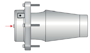
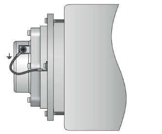
Carry Out Step 3.4 - Use at least one of the available threaded bushings M12 on the top or bottom of the cable joint to connect an earth wire to a fixed earth.
-
-
Carry Out Step 3.5 - Install the Dummy Plug
-
Step 3.6 - Do Not unscrew the screw in the cover of the dummy plug
-
-
Carry Out Step 3.7 - Remove the protecting cap or cover plate from the socket
-
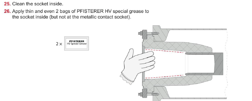
Carry Out Step 3.8 - Clean the surface of the socket
-
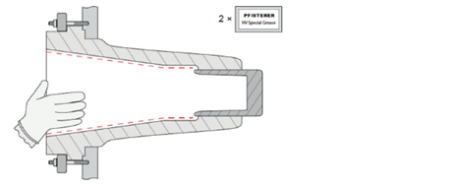
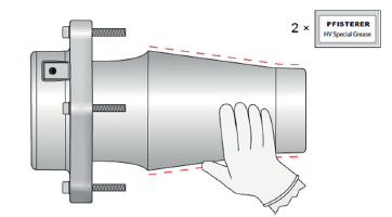
Carry Out Step 3.9 - Grease thinly and evenly the surface of the socket with 2 packages PFIS-TERER HV special grease (but not the metal contact socket), wear clean protective gloves.
-
-
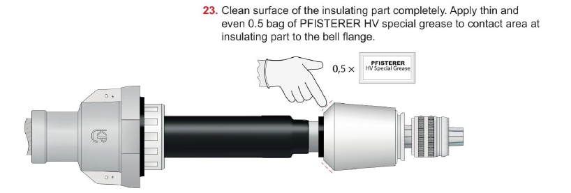
Carry Out Step 3.10 - Clean the surface of the insulating part
-
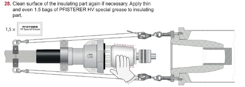
Carry Out Step 3.11 - Grease thinly and evenly the surface of the insulating part with 2 packages Pfisterer HV special grease, wear clean protective gloves.
-
-
Carry Out Step 3.12 - Insert Dummy Plug into socket
-
-
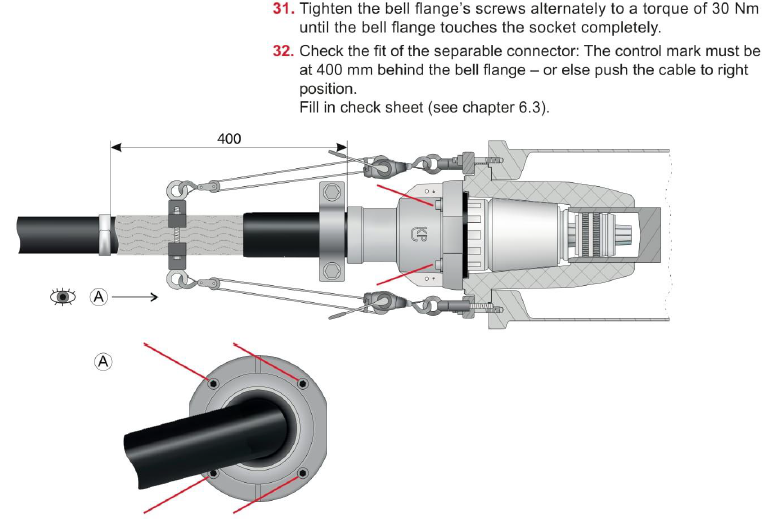
Carry Out Step 3.13 - Tighten the screws reciprocally to a torque of maximum 30Nm.
-
-
Carry Out Step 3.14 - Connect the dummy plug per earthing wire to the earthing point on the clamping ring.
-
-
Carry Out Step 3.15 - Photograph including date/time stamp shall be taken showing the Temporary Testing Connection.
-

Sub Task #4) Removing Temporary Testing Connection
-
Step 4.1 - Ensure the remote end of the cable is connected to the main circuit earth and is locked and E-Permit issued detailing all isolations.
-
Carry Out Step 4.2 - Disconnect the dummy plug per earthing wire from the earthing point on the clamping ring.
-
-
Carry Out Step 4.3 - Loosed the screws reciprocally.
-
-
Carry Out Step 4.4 - Withdraw the Dummy Plug from the socket
-
-
Carry Out Step 4.5 - Before proceeding, prove the absence of voltage, prod a discharge stick into the socket.
-
-
Carry Out Step 4.6 - Carefully withdraw the Connex Connector from the socket.
-
-
Carry Out Step 4.7 - A Pfisterer Size 4 protective cap shall be fitted to the withdrawn Connex Connector providing protection against damage and dirt.
-
-
Carry Out Step 4.8 - Photograph including date/time stamp shall be taken showing the Size 4 Protective Cap installed
-
Carry Out Step 4.9 - Continue the Permanent Installation from Step 2.18.22


Sub Task # 5) Completion
-
5.1 Collect all tools and waste and prepare them for lifting. Clean any stains caused.
-
5.2 Lift off all remaining materials, waste and tools by the crane (if no other works to be done)..
-
5.3 If OSS “Under Rules” sign out all members of the Working Party from the Working Party Register (WPR) before leaving the location.
-
5.4 Close permits to work / safety documents (LOA).
-
5.5 Leave structure
Sign Off
-
The SOC shiftsupervisor needs to sign this document as well. Do not mark this inspection as complete prior to his signature.
-
Signature Tower Foreman / Team leader
-
Signature Vattenfall Representative
-
Comment if applicable
-
Signature SOC Representative
 - duplicate")


 - duplicate")
 - duplicate")