


Title Page
-
Site conducted
-
Conducted on
-
Location
-
Cable ID
-
Prepared by
-
Tick
Sub-Task #1 Preparation
-
Status of installation: cable is pulled into the structure and stored inside the cable storage pit, and the end of the cable is secured and is accessible. This activity shall occur before cable termination.
-
Perform Toolbox talk
-
Check for a valid permit and review the required safety measures
Attached TRA M-00011431 -
For test purposes the ends of the core(s) under test are defined as follows:
Test End A - Test end (Location where the test equipment is applied).
Test End B – non-test end (Remote end of the cable under test). -
Verify your location, the cable ID, cable route and switchgear location and ID.
-
Check in over the radio with the transfer vessel and neighboring teams so that everybody is aware of ongoing works.
-
Check that all tools and test equipment required for the work is available and in good condition, and calibration is still valid.
-
Check cable ends are secured and safe and that if any personnel are present, they are authorised to be so and where applicable safety warning notices are fixed to warn that the cable is under test.
-
Establish and test reliable two-way radio communication between cable test end and if applicable personnel present at the remote non-test end.
-
Ensure that the cable is disconnected from any voltage source.
-
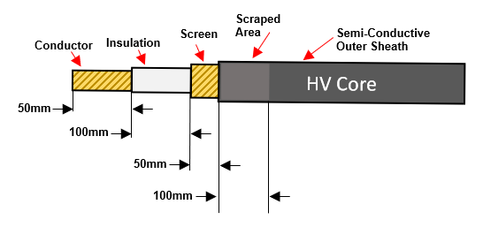
Test End A&B: Release the power cores, remove any end seals, and prepare the HV power cores for attachment to test equipment. Ensure that the prepared and exposed cable end is protected from damage.
-


Sub-Task #2 Phase Check ID
-
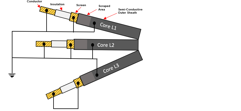
The power cores phases are individually marked as follows:
• TKF – Meter and phase marking is applied to the outer sheath
• Prysmian – Under the screen, core marking is done with a coloured identification tape. -
Test End A&B: Confirm both ends of the power cores have been prepared as per Step 1.10.
-
Test End A: Instruct personnel at the Cable Remote End that Phase Identification Testing will commence shortly.
-
Test End B: Confirm instruction received and understood.
-
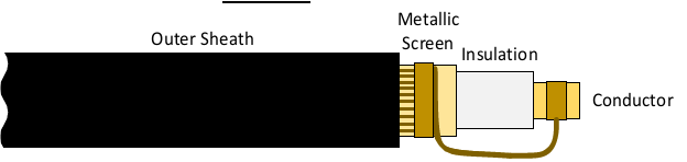
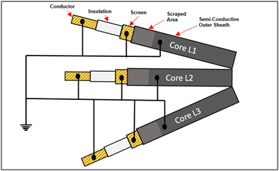
Test End A: Instruct personnel at the Cable Remote End to identify the power core marked L1 / Red coloured tape and to install a shorting link between the conductor and the screen.
-
-
Test End B: Confirm
-
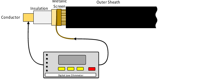
Test End A: Identify the power core marked L1 / Red coloured tape and connect a continuity tester between the conductor and the screen.
-
-
Test End A: Ensure continuity (Low Resistance – 0.01Ω).
-
Test End A: Identify the power core marked L2 / Yellow coloured tape and connect a continuity tester between the conductor and the screen.
-
Test End A: Ensure no continuity (Infinite Resistance – OL).
-
Test End A: Identify the power core marked L3 / Blue coloured tape and connect a continuity tester between the conductor and the screen.
-
Test End A: Ensure no continuity (Infinite Resistance – OL).
-
Test End A: Ensure two of the cores tested have infinite resistance and only one core has continuity, Low Resistance – 0.01Ω.
-
Test End A: Reconnect the continuity tester to the power core with continuity (low resistance) and repeat the test.
-
Test End A: Ensure continuity (Low Resistance – 0.01Ω).
-
Test End A&B: Once continuity is confirmed, attach temporary circuit identificaiton labeliing to either end of the power core.
-
Test End A&B: Verify the phase marking on the outer sheath / colour of the identification tape at both ends of the core are identical.
-
Test End A&B: If the phase marking / colour of the tape differs, report the findings immediately to the Employer’s Representative.
-
Test End A: Instruct personnel at the Cable Remote End to remove the shorting link between the conductor and the screen.
-
Test End B: Confirm.
-
Repeat Steps 2.5 through to and including Step 2.20 for each power core until all selected power cores are tested and temporary identification fitted.

Sub-Task #3 TDR Testing
-
Make a note of the Cable length recorded during Post Lay Testing.
-
Test End A&B: Confirm both ends of the power cores have been prepared as per Step 1.10.
-
Test End A: Instruct personnel at the Cable Remote End that TDR Testing will commence shortly.
-
Test End B: Confirm instruction received and understood.
-
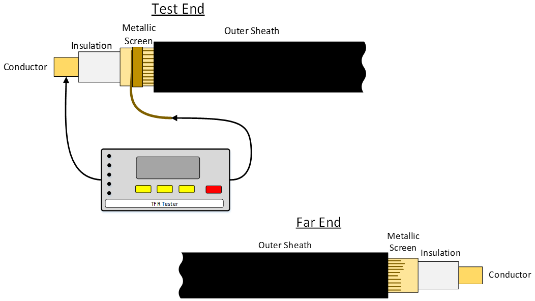
Test End A: Select and identify the HV Core to test and connect it to the TDR Test Unit via test leads.
-
-
Configure TDR Test Unit with correct parameters for cable under test including Pulse Width, Distance Range.
-
The Propagation Velocity (V/2) during SAT was:
• TKF 84.3 to 86.1 m/µs
• Prysmian 79.3 to 80 m/µs -
The acceptance criteria shall be:
• No unexplained events recorded between any conductors i.e. the trace shall be smooth and flat. -
Test End A: Request personnel at the Cable Remote End to verify the cable is supported and not touching any framework or objects.
-
Test End B: Confirm
-
Carry out TDR Testing.
-
Test End A: Verify Pass / Fail Thresholds have been achieved - No unexplained events recorded between any conductors i.e. the trace shall be smooth and flat.
-
Confirm the length displayed on the test equipment equals the value recorded at Post Lay Testing minus any cable cut since .
-
Photograph including date/time stamp shall be taken showing the trace on the TDR screen.
-
Ensure the trace is saved and appropriately stored on the TDR Test Equipment.
-
Remove the test equipment from the power core under test
-
Repeat for each power core until all selected power cores are tested and results verified.
-
Test End A: Inform personnel at the Cable Remote End that TDR Testing is now complete and to standby.
-
Test End B: Confirm


Sub-Task #4 DC Voltage Test of the Over Sheath
-
ELECTROCUTION HAZARD Insulation Resistance Testing presents an electric shock hazard to personnel and additional precautions must be taken due to the applied test voltage of 10kV.
-
Carefully prepare each cable end for test according to the test equipment manufacturers recommended guidelines.
-
Safety regulations for work with electrical equipment:
i. Disconnect completely.
ii. Secure against re-connection.
iii. Test for absence of harmful voltages.
iv. Ground and short-circuit.
v. Cover or close off nearby live parts. -
Protection of the test set-up against direct contact with live parts is required, by using e.g. appropriate:
i. insulation,
ii. covers,
iii. housings, enclosures, guards
iv. barriers,
v. safe distances,
vi. Personnel Protective Equipment (PPE),
vii. Demarcation of Work Area. -
Test End A&B: Confirm both ends of the power cores have been prepared as per Step 1.10.
-
Test End A&B: Connect all conductive elements of the power cores, namely the conductors, screens, and the semi-conductive outer sheath securely to a safety earth connection point
-
-
Test End A&B: Ensure that suitable barriers, screens, and warning signs are in place as required and that a controlled and secure means of access to both the cable end under test and the Cable Remote End is in place and effective.
-
Test End A&B: Re-check two-way radio communications between test personnel at the cable end under test and any test personnel that shall be present at the Cable Remote End. Where provided, re-test the secondary ‘back up’ communication.
-
At all stages of testing a two way ‘command and confirm’ communication procedure MUST be strictly adhered to between personnel at the cable end under test and personnel at the Cable Remote End.
If at any stage during the testing procedure radio communication is lost or an instruction, communication or transmission is not confirmed by the other party the test must be stopped immediately and the cable returned to a safe condition as quickly as possible i.e. test voltage removed, cable discharged, proved dead and earthed. -
Test End A: Instruct personnel at the Cable Remote End that Insulation Resistance Testing will commence shortly on the “Sheath”.
-
Test End B: Confirm instruction received and understood.
-
Test End A: Select and identify the HV core to test and instruct personnel at the Cable Remote End to firstly disconnect the safety earth from the screen and the conductor. And secondly to install a shorting link between the screen and the conductor.
-
Test End B: Confirm earth disconnected and a shorting link has been installed between the screen and the conductor.
-
-
Test End A: Instruct personnel at the Cable Remote End to stand clear of the cable end until further instruction and that testing will commence.
-
Test End B: confirm personnel standing clear.
-
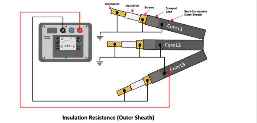
Test End A: Connect the black (HT Test Lead) to the “Screen” and the “Conductor” of the core under test.
-
Test End A: Connect Red Lead to the semi-conductive outer sheath of cable under test.
-
Test End A: Power core under test - remove the earth connection from the conductor and the screen.<br>Ensure all other earth connections remain fitted.
-
-
Test End A: Carry out the Insulation Resistance test on the “Sheath”
-
The test voltage shall be applied for 1 minute.
-
Photograph including date/time stamp shall be taken showing the digital readout on the test equipment
-
Test End A: discharge the power core under test via IR test set after completion of the test.
-
Test End A: switch the test set off and apply the discharge stick to the core under test and hold.
-
Test End A: re-apply safety earth connection to the “Screen” and “Connector” under test, remove the discharge stick.
-
Test End A: Advise personnel at the Cable Remote End that the test is complete, the cable/conductor is proved dead, the conductor safety earth connection is applied at the test end and that the cable is safe to approach.
-
4.27 Test End B: confirm.
-
Test End A: Request personnel at the Cable Remote End to remove the link between the screen and the conductor and to reconnect the screen and the conductor to the safety earth.
-
Test End B: confirm.
-
Test End A&B: repeat for each HV core until the insulation testing of the sheath has been completed on all three cores.
-
Test End A: Instruct personnel at the Cable Remote End that Insulation Resistance Testing on the “Sheath” is now complete and to standby.
-
Test End B: Confirm instruction received and understood.
-
Proceed to Insulation Resistance Tests.


Sub-Task #5 Insulation Resistance Tests
-
Test End A: Instruct personnel at the Cable Remote End that Insulation Resistance Testing will commence shortly.
-
Test End B: confirm.
-
Test End A: Select and identify HV core to test and instruct personnel at the Cable Remote End to disconnect safety earth connection from the “Conductor”.
-
Test End B: Confirm earth disconnected.
-
Test End A: Instruct personnel at the Cable Remote End to stand clear of the cable end until further instruction and that testing will commence.
-
Test End B: confirm personnel standing clear.
-
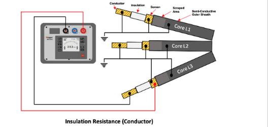
Test End A: Connect the black (HT Test Lead) to the conductor of the core under test.
-
Test End A: Connect Red Lead to the screen of the core under test.
-
Test End A: Power core under test - remove the earth connection from the conductor.<br>Ensure all other earth connections remain fitted.
-
-
Test End A: Carry out the Insulation Resistance Test
-
The test voltage shall be applied for 5 minutes.
-
Photograph including date/time stamp shall be taken showing the digital readout on the test equipment.
-
Test End A: discharge the power core under test via IR test set after completion of the test.
-
Test End A: switch the test set off and apply the discharge stick to the core under test and hold.
-
Test End A: re-apply safety earth connection to the conductor under test, remove the discharge stick.
-
Test End A: Advise personnel at the Cable Remote End that the test is complete, the cable/conductor is proved dead, the conductor safety earth connection is applied at the test end and that the cable is safe to approach.
-
Test End B: confirm.
-
Test End A: Request personnel at the Cable Remote End to reconnect the conductor to the safety earth.
-
Test End B: confirm.
-
Test End A&B: repeat Steps 5.3 to 5.19 for each HV core until the insulation testing of the sheath has been completed on all three cores.
-
Test End A: Instruct personnel at the Cable Remote End that Insulation Resistance Testing is now complete and to standby.
-
Test End B: Confirm instruction received and understood.
-
Test End A&B: Once the third and final core has been tested, the safety earths shall remain fitted for a period of no shorter than 15 minutes before proceeding.
-
-
Test End A&B: Disconnect the safety earth from the screen wires, the outer sheath and the power core conductors.
-
Test End A&B: If termination of the power cores is to be carried out immediately after completion of the prior to termination testing by the same team, the cable ends may be left exposed, proceed to Step 6.6.
-
If termination is to be carried out later by different personnel seal the power cores with end caps, proceed to Step 5.27.
-
Remove the 10cm of the power core that was prepared for the prior to termination tests.
-
Thoroughly clean, degrease and dry the outer sheath surface providing a surface suitable for good adhesion of the end cap.
-
Install suitable adhesive lined end seal caps onto the power cores with either hot or cold cure adhesive according to the manufacturer’s installation procedure.
Sub-Task #6 Completion
-
Are you performing this Sub-Task
-
6.1 Take pictures of the as left situation on MPs and on OSS cable deck
-
6.2 Collect all tools and waste. Prepare them for lifting off of the tower. Clean any stains caused
-
6.3 Close hatches/doors.
-
6.4 Lift off equipment by the crane of the ISV (if no other works to be done).
-
6.5 Leave Structure.
Sign off
-
Client present?
-
No Client present
-
Client Representative
-
Comment if applicable
-
V&SH Tower Team Lead
-
SOC HV Supervisor to review and confirm installation work carried out satisfactory meeting the specified requirements and tick complete.
-
SOC HV Supervisor
-
Comment if applicable
 - duplicate")
 - duplicate")


 - duplicate")
 - duplicate")

 - duplicate")