


Information
-
To be Read in Conjunction With Mitchells & Butlers Mechanical & Electrical Performance Specification on Last Page of This Report
-
Client / Site
-
Date
-
Prepared by
-
Location
-
Weather Conditions
- Sunny
- Raining
- Damp
- Dull / Overcast
-
General Overview of Installation
-
Exclusions from This Report
Visual & Functional Survey Of Installation
Main Supply Characteristics
-
Approx Age & Condition
-
Single Phase, Two Phase & Neutral, Three Phase & Neutral Supply
-
Incoming Supply Size
- 63A
- 80A
- 100A
- 125A
- 150A
- 160A
- 175A
- 185A
- 200A
- 225A
- 250A
- 300A
- Other
-
Main Switch Voltage Rating:
-
Main Bonding to Incoming Services
- Water 6mm sq
- Water 10mm sq
- Water 16mm sq
- Water 25mm sq
- Water 35mm sq
- Water 50mm sq
- Gas 6mm sq
- Gas 10mm sq
- Gas 16mm sq
- Gas 25mm sq
- Gas 35mm sq
- Gas 50mm sq
- Structure 16mm sq
- Structure 25mm sq
- Structure 35mm sq
- TBC
-
Supplementary Bonding Including Trade Kitchen - Earth bonding should be present to any stainless steel surfaces where electrical equipment is used, to remove the risk of electric shocks.
- Water 6mm sq
- Water 10mm sq
- Water 16mm sq
- Water 25mm sq
- Water 35mm sq
- Water 50mm sq
- Gas 6mm sq
- Gas 10mm sq
- Gas 16mm sq
- Gas 25mm sq
- Gas 35mm sq
- Gas 50mm sq
- Structure 16mm sq
- Structure 25mm sq
- Structure 35mm sq
- TBC
-
Is a Voltage Optimiser installed
-
Has the Phase Rotation been confirmed as correct
-
Ask BDM to inform Dale Fenton in the Energy Team Dale.Fenton@mbplc.com - 07547 936271
Distribution Board
-
Location of DB, Age, Condition - Number of Spare Ways - RCD/RCBO Protected Circuits - Circuit Charts,
Are DB's & MCB's now Obsolete - Will They Require Replacement - Is There 25% Spare Capacity - Will There Be 25% Spare capacity Once New Equipment Has Been Installed -
Distribution Board Description
Internal Lighting
-
Dimmer Panel - Make & Model
- Mode Mirage MP-06-08
- Mode Mirage MP-10-01
- Mode Mirage MP-10-04
- Mode Tiger TP-06-09
- Mode Tiger TP-06-18
- Mode Tiger TP-10-06
- Mode Tiger TP-10-12
- Mode Tiger SPP-06-08
- Lutron Graphik Eye GRX-***
- Grid Switches
-
Are Dimming Zones Clearly Marked on Layout Plan
-
Dimming Controls
- Slide Dimmer
- Scene Setting Plate
- Lutron on Panel
- Other
- None
-
Is Trade Area Visible from Dimmer Controls
-
Linked to Intruder Alarm
-
Linked to Fire Alarm
-
BOH Area Lighting on PIR (Store Rooms, Corridors, Cellar's)
-
Are Fire Hoods / Fire Rated Fittings Installed
-
Confirm Depth of Recess for AR111 Type Fittings
-
Is Neon Signage Installed
-
Appropriate Fireman's Switch Is Installed
External Car Park, Gardens, Patios, Shelters, Walkways & Signage Lighting
-
Controlled Via & Timeclocks Correctly Set for Trading Hours
- Timeclock
- Photocell
- Timeclock & Photocell
- Manually Switched by Staff
- None
-
Lighting Within Shelters is Switched with External Lighting or Local Touch Timer Switches
-
External Heaters To Have individual Touch Timer Switches, with Isolation Within the Pub
-
External Lighting Operational
-
GM to Log P2 Call Out with Electrical Contractor in First Instance
-
Type of External Lighting - SON - HQI - LED - Etc
-
Service Yard and Staff Exits Covered By PIR Lighting
-
Signage Lighting Operational
-
GM to Log P2 Call Out with Electrical Contractor in First Instance
Emergency Lighting
-
Is Emergency Lighting Correctly Switched - No Lighting Spurred of Emergency Circuits
-
Charging LED's Visible
-
Suitably located / Full Coverage
-
is Emergency Exit Signage of the Correct Type And Direction Arrows Correct
Lighting and Small Power (socket outlets, switches etc)
-
This policy also applies to Managers flats and shared staff accommodation.
User checks
All users of electrical equipment are expected to check it prior to use to ensure it is visually safe.
All Team Members are trained how to inspect electrical equipment using Training Shorts 1.10 and trained that defects must be reported to their Manager.
Multi-adaptors
The use of un-fused multi-adaptors is not allowed due to the potential for socket overloading and fire risks.
Any extension lead must be a 13 Amp fused gang socket that plugs into the wall with a varying length flex to the adaptor sockets.
Any PVC Sockets to Be Replaced With Metalclad Type On Cookline ? -
Age & Condition of accessories
-
Are Additional Safety Switches/Isolators for Electric Fryers Installed (See Fryer Isolation Manual Reset Schematic Drawing in Performance Spec V9.1)
Fire Alarm
-
Fire Alarm System Category
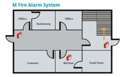
- M - Manual Fire Alarm System
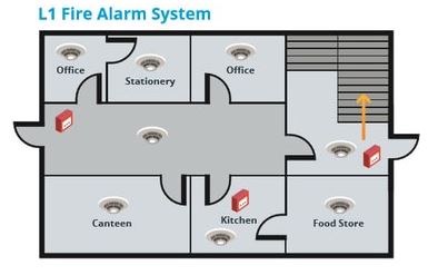
- L1 - All Areas
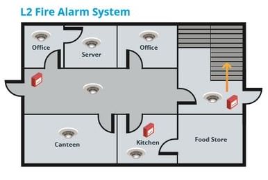
- L2 - Defined Areas in Addition to L3
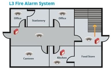
- L3 - Escape Routes & Rooms Onto Escape Routes
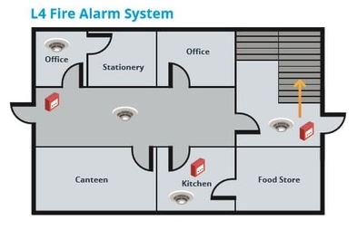
- L4 - Escape Routes
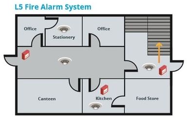
- L5 - Defined Specific Areas
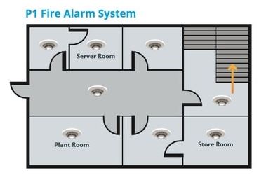
- P1 - Full Building Protection
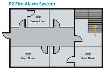
- P2 - High Risk Area Building Protection
-
Manual Fire Alarm System
These are the least sophisticated of systems, which rely on the building’s occupants to detect a fire and provide a warning to others. When a fire is discovered, employees must activate the alarm manually, in order to alert everybody else in the building to the danger.
A typical example of a manual fire alarm system is a series of break glass units, which are installed at each point of exit in a building. This allows those escaping a fire to raise the alarm as they leave the danger zone.
Manual fire alarm systems can be effective but due to reliance on individuals, it means that there can be an increased risk of employee and visitor safety, especially if the site is not highly populated with few people to raise an alarm. -
-
L1 All Areas
This is the most comprehensive fire alarm system, which features detectors in all areas of a building where a fire could feasibly start. Detectors are linked up to a centralised alarm system which alerts the whole building should a fire break out.
The objective of this setup is to ensure that inhabitants are given the earliest possible warning, should an emergency occur. -
L2 - Defined Areas in addition to L3
Fire alarm systems that fall into this category feature automatic detectors in all rooms that form part of an escape route, including corridors. Detectors also need to be installed in all high-risk rooms, such as kitchens, boiler rooms and areas with heavy plant machinery.
L2 systems are effective at providing an early warning to occupants beyond the source of the fire and those working in high risk areas. Examples of properties that typically employ this system include factories or medium sized residential premises. -
L3 - Escape Routes & Rooms Onto Escape Routes
Standard life protection systems feature detectors in all escape routes and rooms that open onto an escape route. The objective of this system is to ensure that all inhabitants of the building are given enough warning to escape a fire, before their exit is impeded by the presence of flames, smoke or toxic fumes.
This category of fire alarm system is typically adopted in regular sized office blocks and commercial buildings that have flights of stairs.
It would be the ideal standard for Hotel type accommodation as a minimum -
L4 - Escape Routes
An L4 category fire alarm system consists of detectors within escape route areas only, such as in corridors and stairways. Any circulation areas that make up part of the escape passage should also be fitted with a detector when the site is classed within this fire alarm category.
Commercial properties that generally adopt this category of system are those that have a lower level of risk. -
L5 - Defined Specific Areas
L5 fire alarm category systems are those that are installed to tackle a specific fire risk in a certain area of a building. For example, if there is a room in a building that poses an exceptional hazard because of the items stored there or business activities carried out there.
An L4 category system may be appropriate for the building in general but an L5 system will recognise the level of risk presented. -
P1 - Full Building Protection
A P1 fire alarm system involves installing detectors in all areas of the building. The objective of a system like this is to protect buildings that are critical to the operations of a business.
By implementing maximum protection across a whole site, those in charge of fire safety can ensure that any fire that breaks out is detected and neutralised as quickly as possible. This lowers the risk of damage and disruption and in turn, the financial impact that a fire could inflict on a company. -
P2 - High Risk Area Building Protection
In a category P2 fire alarm system, fire detectors are installed in high risk areas only. Whilst a system like this does not provide the same level of cover as a P1 solution, it does provide early detection for the most likely sources of a fire.
This early detection will decrease the time it takes for the fire services to arrive on the scene and will help to minimise any damage to the property and losses to the business -
Approximate Age & Condition of Panel
-
Does GM Have Fire Alarm Panel Access Codes and Suitable Call Point Test Keys
-
Fire Alarm System - Any Alarms / Faults Displayed
-
GM To Log A P1 Call With The Electrical Contractor
-
Approximate Age of Standby Batteries
-
Approximate Age of Devices
-
Detectors Installed With Remote Indicators in Inaccessible Voids or Locked Rooms
-
Call Points Numbered and test keys present - All break glass call points should be numbered so that a different point can be checked each week. All call points need to be tested a minimum of 4 times a year. If there are more than 12 call points (up to 24 call points) you must test 2 call points per week.
-
Means of Raising Alarm - All Systems To Have Suitable Sounders / Bells and Visual Alarm Devices to Notify Occupants of Alarm State - IN HOTELS COVERAGE IS REQUIRED TO WAKE SLEEPING PERSONS
- Sounders
- Bells
- Beacons
-
Are Sounders, Bells & Beacons of The Same Type Throughout The Premises
-
Zone Chart Displayed - Panel Clearly Identified
-
Linked to Intruder Alarm
Disabled Toilet Alarm
-
DDA Alarm Fully Compliant & Operational
-
GM to Log P2 Call Out with Electrical Contractor in First Instance
-
DDA Alarm Audible and Visible from Bar Servery
-
Does Pullcord reach the floor
Energy Saving & Sustainability Opportunities and Already Installed
-
Repair leaks and insulate building repair existing systems
Photo Voltaic Solar panels
Rainwater harvesting for toilet flushing
Heat recovery from kitchen extract
Fireplace for supplementary heat generation for heating & hot water
Steam recovery
Geothermal
Energy efficient appliances
Timers
Average temp sensors
Air/Ground heat source
Hydrogen Boilers
Wind power
Archimedes Screw
Insulation of pipework, walls, lofts etc
Air tightness
Close doors & windows
Tree logging & Fire Places & Furniture
Item
-
undefined
Essential Works & Costs
- Item
-
Description of Works
-
Estimated Costs
Recommendations & Repairs
-
RECOMMENDATIONS
Item
-
Details:
Performance Specification Electrical
-
ELECTRICAL SPECIFICATION REQUIREMENTS
The scope of works may include, but shall not be limited to, the following:
Production of design drawings and calculations
Liaising with electricity power network and meter operators
Liaising with MAB specialists/directs
Main and sub main distribution switchgear and cabling
Sub-metering
Surge Protection
Containment systems installation for electrical installation and for specialists/directs
Circuit cabling
Small power installation
General and emergency lighting installation including controls
Electrical Supplies to all Signage
Electrical Supplies to Specialist equipment
Mechanical Services power supplies and containment
Fire alarm system
CCTV and security systems (power supplies and containment only).
Telephone installation (power supplies and containment only)
Data Installation (power supplies and containment only)
Earthing and bonding
Labelling
Testing and commissioning
Record documentation
All switchgear, distribution boards and isolating switches shall be identified as to their function
and operating voltage, and where units are denoted by a reference code this code shall be included.
The description of a units’ function shall give a clearly understood definition. Permanent typed labels
(Dyno tape or similar approved) shall used to identify distribution boards and isolators.
The installation shall be divided into separately controlled circuits, as required to maintain
phase balance and phase distribution within the building, further sub dividing where necessary to ensure
compliance with British Standards including earthing and equipotential bonding. Dedicated ‘clean earth’
systems shall be provided to all communications/AV equipment.
Equipotential Bonding is not a requirement where an extraneous potential difference is not possible. MAB has a mix of metallic and non metallic pipework entering the building. The highest risk being where staff are likely to work off metal benching or shelves. Noted this will apply to legacy buildings where less modern distribution equipment and circuit protection exists. Where entering services are polyethelene and bonding may be unnecessary.
New distribution boards shall be manufactured from sheet steel and be fitted with miniature circuit breakers (mcbs) or residual current devices (RCD/RCBO). Each distribution board shall be fitted with a hinged lockable door and an integral isolator. Metered distribution boards or separate meters should be used to comply with Part L of the Building Regulations using TM39 as a guide. Distribution boards shall include a minimum 25% space capacity, on each phase, to be achieved at completion and the electrical installation shall be equally balanced, so far as is reasonably practicable, across all 3 phases. RCD protection shall be incorporated in accordance with BS 7671 to all appropriate circuits (new or existing re-used).
Where existing distribution equipment is deemed appropriate and compliant for reuse, it shall be fully serviced, cleaned down and retested.
From the MAIN distribution board, separate distribution boards / supplies shall be provided to serve the following where required: Kitchen general services (contactor controlled with em. stop), Kitchen 24hour services, Lighting Power, Lighting control panels / dimmers, Over-door heater, Fire alarm panel, EPOS (clean supply), Heating Plant, External Lighting, HVAC Plant, Water Heating plant, Cellar Services.
Surge protection shall be included within/at the MAIN distribution board. This shall be connected to the incoming supply in accordance with the manufacturer’s recommendations complete with appropriate protection. Surge protection shall be provided at the distribution board where any circuit feeds external equipment.
The contractor shall provide all supplies including isolators, socket outlets, switched fused
connection units and un-switched fused connection units as required by the kitchen supplier.
Exact positions of the kitchen equipment and electrical supply locations shall be obtained from the kitchen
supplier prior to installation. Refrigeration sockets should not be RCD protected due to nuisance tripping
risks. Where sockets and any connections units are to be installed in potentially damp/cold or washdown
areas they shall be a suitably IP rated.
All outlet/connection units shall be engraved/labelled to identify circuit number and item of
equipment served. Refrigeration socket outlets shall be specifically labelled for that equipment only.
Routing of cabling behind cooklines to be as low as possible and within metal containment to minimise damage to cabling.
All 13A socket outlets within offices are to be mounted within 3 compartment white, moulded plastic, dado trunking mounted at 1000mm above finished floor level. The trunking shall be complete with proprietary bends, tees, couplers, etc., to form a complete installation, and shall include a flat bend to rise to the ceiling void.
Front of House sockets to be 13A Twin type with facia to match brand style. Sockets to be complete with USB C and USB A 2.1A outlets for phone and laptop charging.
The contractor shall be responsible for the careful handling, unpacking and installation of all luminaires including final assembly in accordance with the manufacturer/suppliers’ instructions. The contractor should not alter UKCA certified luminaires on site. All front-of-house luminaire lamps shall be supplied by RYNESS and shall be delivered with the particular luminaires. Where luminaires do not incorporate integral intumescent hoods the Contractor shall supply and install
separate Intumescent fire hoods to each luminaire where fitted through a fire rated ceiling. The Contractor shall include for lighting any accessible roof spaces with surface fixed batten luminaires switched from surface mounted passive-infra-red motion sensors with a run-on time of 10 minutes (an over-ride should be provided for maintenance operations).
Luminaires within the trading spaces shall generally be dimmer controlled from a master lighting control panel located back of bar (in a position where most lighting can be seen), controlled in zones to suit the space layout and use. The contractor shall install dimming to the circuits in the Trading area only and where specified by the brand designer.
Preferred dimming system to be utilised shall be:
MODE LIGHTING “TIGER” PACKS (TP-10-06-RCBO) with “TIGER” SCENE SETTING CONTROL PLATE TP-SGP-55-BLK-BSS-MB with TP-S-PBR-55 10 button control plate with black buttons with facia (polished brass, brushed stainless steel, polished chrome or white) to suit the brand. The contractor shall assist the brand designer with programming of scenes as instructed.
The dimming scenes shall be set up to the designers levels with a minimum of four settings;
Cleaners / Day / Evening / Night.
Cleaners = all FOH lights on full.
Day = Evening and Night are to be set to suit the brand the dimmer is being installed in. An example
of settings is included within the appendix of this specification.
The schedule of confirmed settings relevant to the site being set up shall be a fixed to the wall adjacent to the dimmer to future maintenance as a record of the initial settings i.e. the Commissioning sheet as provided by the MODE commissioning engineer. A short form guide is to be positioned above the button / or slider control panel to confirm the buttons set up along with the description and envisaged time of day, i.e.
• Button 1 = Cleaner = All lights ON,
• Button 2 = Day = From Open to public till 4pm,
• Button 3 = Evening = From 4pm till 7pm,
• Button 4 = Night = From 7pm to Close.
Note the above is the minimum, the Electrical Contractor is to discuss and agree any adaptions and/or amendments to the above to suit the brand.
The main lighting control panel shall be engraved to identify areas under control.
control.
The commissioning of dimmed scenes to take place after dark to ensure the correct levels of lighting at achieved.
Guidance on dimmed lighting circuits is as follows;
• Lamps of different types are to be kept on separate circuits.
• Each Circuit requires several lamps per circuit, ideally 20-30 depending on
wattage of lamps.
• 15W Minimum
• 150W Maximum or 30 Lamps which ever comes first i.e. 10lamps at 15W each,
would be a maximum or 30 lamps at 3W each would be a maximum.
• LED tape/Strip Light is to have 4 (230v) drivers maximum.
• Lamps are to be leading edge type technology.
• Emergency Lighting is not to be wired to a dimmed circuit.
MODE Dimmers have Fire Alarm interfaces / Intruder Alarm Interlocks which are to be wired with Volt Free connections and not 12V or 24V.
MODE offer a telephone troubleshooting service, 01920 462121, option 2.
The lighting to the kitchen areas shall be switched locally and not dimmed.
The contractor shall include for an interface so that selected lighting circuits will operate on the activation of the intruder system, the selected lighting circuits shall be confirmed prior to installation. The interface shall also ensure that any dimmed lighting is returned to full brightness in the event of a fire alarm condition.
Within toilets the lighting shall be controlled via recessed ceiling mounted 360° presence detectors with adjustable time delay. Store cupboards, staff rooms, etc., shall be fitted with presence detectors to automatically switch on-off lighting. Kitchen and Plant room lighting should be manually switched.
Cabling shall be carried out using LSZH cables concealed wherever possible. Where
concealment is not possible routes shall be agreed and suitably protected.
Any emergency lighting shown on Designer drawings is for guidance only and the contractor shall design strictly to the relevant BS. Emergency lighting shall be self-contained, 3hour duration using LED sources wherever possible.
Emergency lighting test key-switches shall be provided adjacent to the general light switch for an area or at the local distribution board. Key switches shall be rated at 20A DP. The key switch shall serve as the test switch for the emergency lighting and shall be wired such that only the emergency lighting is brought into operation during testing and does not extinguish other non-emergency luminaires.
All these switches shall be labelled as to the area being tested. Allow for demonstration of the system to the Fire Officer/client at handover.
Any Fire detection and alarm provisions shown on designer drawings is for guidance only and the contractor shall design strictly to the relevant BS. Design, supply, install and commission shall be in accordance with all relevant parts of the British Standards. Smoke detection shall be provided to voids in excess of 800mm depth. The fire alarm system shall be conventional / 2 wire type or analogue addressable, EN54 compliant with appropriate fire indications and protected /tamperproof controls. The fire alarm shall be connected to the intruder alarm communicator to provide a fire alert to the central monitoring station. The fire alarm panel shall be located in accordance with the Local Fire Officer’s requirements and shall provide all facilities required by the British Standard. Sounders and visual alarm devices shall be located throughout the building to achieve the required audibility and illumination levels and to satisfy the requirements of the Local Fire Officer. See technical spec for automatic function and zone requirements. In multiple occupation buildings the system shall be connected to the landlords’ fire monitoring system in accordance with landlords’ requirements and details.
As a minimum the fire alarm is to provide L5 classification for Restaurants with L3 classification for hotels with the following minimum coverage related to the areas
described below.
• Panels ;
• 1No. at front entrance lobby.
• Alternative to above 1No. at rear entrance with repeater at front entrance where
• the business is a unit i.e. part of a landlord complex of shops/restaurants.
• 1No. at entrance to flat as a repeater for live in manager / occupant.
• ii. Smoke Detection
• FOH, number dependant on any deep beams and with coverage close to gas
• fires and open pass cooklines.
• b. Any BOH store room that’s located off an emergency exit route.
• Cleaners store (if it doesn’t contain a sink) and is bigger than 1m2
• COSHH store (if it doesn’t contain a sink) and is bigger than 1m2
• BOH cellar
• BOH escape corridor or room if its on an escape route.
• A live in flat entrance Corridor on live side of flat door.
• Mechanical & Electrical Services – MAB Performance Specification
• FOH WC, One per cubicle if cubicles are individual, One per room where open
ceiling
• Voids above ceilings when greater than 800mm
• PHT/Assisted Access WC
• Kitchen open prep areas, not covered by heat detection.
• Commercial office- dependent on the office location (directly off an escape
• route/ under accommodation).
• Commercial office within a single private dwelling flat or HiMO
• Commercial store within a single private dwelling flat or HiMO.
• Main boiler/plant room
• Extraction duct cupboards where the pass through accommodation if not
• adequately enclosed in fire resisting construction.
• In staff accommodation classed as HiMO in all habitable rooms (bedrooms,
lounge), stores > 1.0m²
. In hotel accommodation all bedrooms.
. Escape route Corridors
iii. Heat Detection
• Kitchen where the cookline is open and has dish wash areas and open prep areas.
• b. Cleaner store (if it contains a cleaners sink)
• c. COSHH store (if it contains a sink)
• d. Glasswash Area
• iv. Break Glass/Manual Call Point
• At kitchen exit
• At kitchen cookline secondary exit
• Behind Bar FOH for staff managed FOH area
• area
. At the end of hotel corridors
v. Sounders
• To achieve audible coverage of site and to wake sleeping persons.
vi. Beacons
• To FOH
• To all WC’s, team room WC being the exception if adjacent Team Room
• To Cookline
• To Team room
The contractor shall supply and install power supplies and containment for the “direct”
installations as required such as CCTV, intruder alarm, sound system, IT/BRS and telecom in accordance with the specialists’ requirements. TV signal distribution shall be designed and installed where required.
A door bell system shall be provided between the front door, delivery door and Office.
The contractor shall carry out a risk assessment of the site to ascertain if a lightning protection system is required. Full details of the risk assessment shall be submitted with the tender return.
The Contractor shall co-ordinate with all specialist trades and direct contractors e.g. Cellar Services , Security, Data etc. and provide all necessary attendances and supervision as to the use of containment provided.
The contractor shall install a “last man out” key-switch at the main entry/exit point, to control Trading area exit route lighting.
Car Park charge points are operated by BP PULSE. Systems are only be amended, altered or worked on by BP PULSE and no other contractor.
The contractor shall install manual reset function to fryer circuits see schematic within appendix.
The contractor to install the appropriate fireman's isolation switch where neon or discharge lighting is to be included within the front of house lighting layout. See schematic within appendix.


