Information
-
To be Read in Conjunction With Mitchells & Butlers Mechanical & Electrical Performance Specification on Last Page of This Report
-
Client / Site
-
Date
-
Prepared by
-
Location
-
Weather Conditions
- Sunny
- Raining
- Damp
- Dull / Overcast
-
General Overview of Installation
-
Exclusions from This Report
Visual & Functional Survey Of Installation
Mains Cold Water
-
Water Meter Location
-
Stop Cock Location
-
Incoming Water Pipe Size
-
Cold Water Main Pipe Material Type
Cold Water System
-
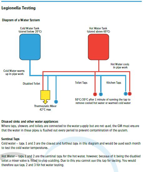
The Manager must test water temperatures each period (every 28 days) to ensure cold water is stored
below 20°C -
General Overview & Reported Issues
-
Hard Water Area Check - https://www.kinetico.co.uk/hard-and-soft-water-explained/hard-and-soft-water-uk
-
Is Water Conditioner Installed
-
Cold Water Temp
-
Incoming Water Supply Mains Pressure - Gravity Fed - Boosted
-
Is Water Pressure Sufficient
-
Visible Pipework is Suitably Lagged and labelled
-
Guest Toilets Have Minimum Water Volume of 6L

Cold Water Storage Tanks
-
CWS Tank Location
-
CWS Tanks Accessible
-
What is required to safely access CWS Tanks
- Loft Ladder
- Loft Boarded Out
- Lighting
-
CWS Storage Tank Type
- GRP
- PVC
- Pre-Insulated
- Galvanised Steel
- Other
-
CWS Tank Ball Valve unobstructed and fully operational
-
GM to Log P2 Call Out With Building Contractor
-
CWS Tanks Clean
-
GM to Log P2 Call Out With Building Contractor
-
CWS Tanks have Lids
-
CWS Tanks have Lagging
Hot Water System
-
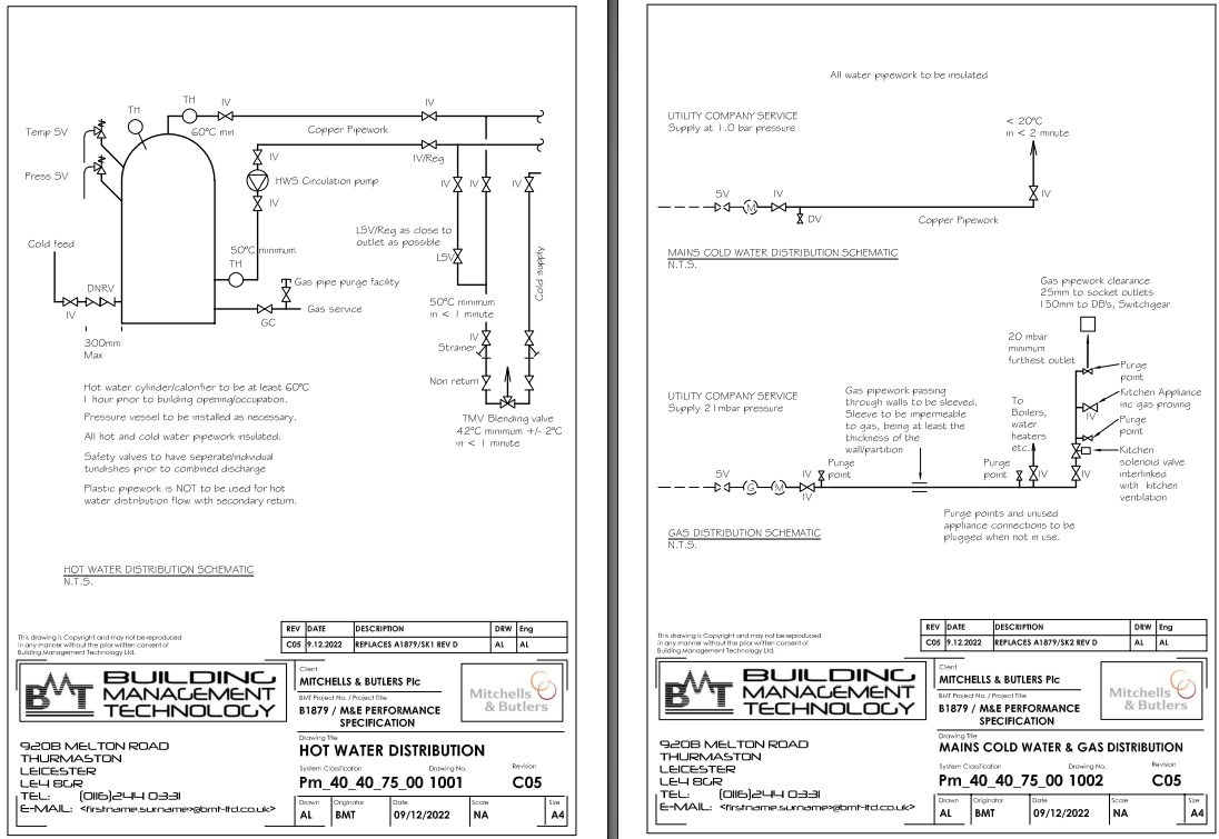
The Manager must test water temperatures each period (every 28 days) to ensure hot water is stored above 50°C to prevent Legionella growth conditions being present.
Hot Water temperatures must be 50-55°C after one minute to prevent burns and scalds.
Where temperatures are recorded above this the hot water cylinder must be adjusted. If necessary by a reactive maintenance contractor. -
General Overview & Reported Issues
-
Is Hot Water Recovery Sufficient During Busy Periods
-
Water Heaters, Number Of - Make - Model Age & Condition
-
Time Clocks Correct & Operational
-
Hot Water Temp
-
Secondary Return Pumps Fully Operational
-
GM to log P2 Call Out With Mechanical Contractor
-
Pressure Relief Valves To Discharge Externally From Plant Room Via Tun-Dish and Copper Pipework for Minimum 1.5m then to PVC Pipework
-
The contractor shall supply and install thermostatic blending valves (TMV2/3) which serve wash basins and any other areas used by the general public and to staff wash hand basins that are not within the kitchen. The Contractor shall check that the taps, supplied and installed by building or catering contractors, to basin/s do not contain an integral thermostatic blending valve.
Approval shall be obtained before the contractor “doubles up” thermostatic blenders. Particular reference to DDA basins in Assisted WC’s.
Temperature of hot water to be set to 42°C +/- 2°C Contractor to use MAB standard handover document to record the temperature at each outlet. -
TMV's on Basins
-
TMV or Blended Tap in Disabled Toilet - Either a mono block mixer tap or a thermostatic mixer valve to the hot tap to achieve 42°C MAX
Mains Gas Supply
-
Gas Meter Size
- U6
- U16
- U25
- U40
- U65
- U100
- U160
-
Gas Safety Labels Present
-
Is There capacity for Additional Equipment
LPG Gas Supply
-
Does LPG tank Enclosure meet legislation? All compounds should have a concrete base; compound with 1.5 metres clear from face of tank; chain link fence; two access gates; and no combustible materials within 3 metres of tank face. LPG tanks adjacent to vehicular access may require protection.
-
Does LPG Enclosure Comply
-
Is There Capacity for Additional Equipment
Heating - Based on M&B Performance Specification
-
Internal Conditions to be used as the basis of performance design:
BAR, RESTAURANT
• Winter – Heating - 21°C
• Summer – Cooling - 21°C +/- 2°C
BACK OF HOUSE CORRIDORS
• Winter – Heating - 18°C
TOILETS
• Winter – Heating - 18°C
STAFF AREAS
• Winter – Heating - 21°C
Acceptable Internal Conditions during open to the public hours.
BAR, LOUNGE, RESTAURANT
• WINTER – heating seasons: 21°C +/- 1°C
• SUMMER – cooling seasons: 21°C +/- 4°C -
General Overview & Reported Issues
-
Boilers, Number Of - Make - Model Age & Condition
-
Boiler Correctly Sized for Installation to Achieve Minimum Performance Specification
-
Has Endotherm Been Added to System
-
Date & Litres Added (From label on front of boiler)
-
Heating Pressure Stable
-
System is Zoned and Zone Valves Operating Correctly
-
All Circulation and Shunt Pumps fully operational
-
GM to log P2 Call Out With Mechanical Contractor
-
Pressure Relief Valves To Discharge Externally From Plant Room Via Tun-Dish and Copper Pipework for Minimum 1.5m then to PVC Pipework
-
Time Clocks Correct & Operational
-
Thermostats Operational
-
Number of Radiators on Heating System
-
LST Radiator fitted in Disabled Toilet
-
TRV's Fitted to All Radiators and Operational
Boiler Room Ventilation Interlock System (If Installed)
-
Gas Interlock Make/Model & Method of Monitoring
-
Interlock Correctly Installed and Operational
-
GM to log P1 Call Out With Mechanical Contractor
-
CO Detector Present
-
Emergency Cut Off Buttons Functional
-
GM to log P1 Call Out With Mechanical Contractor
Kitchen Ventilation Interlock System
-
(BSKVP 20) Supply & Extract Ventilation Gas Interlock
The Contractor shall install the complete catering kitchen ventilation interlock system. The system shall comply wholly with the details specified within the British Standard.
A kitchen ventilation interlock system must be installed. The interlock panel shall be installed adjacent to the supply and extract speed controllers within the kitchen.
The gas interlock should be used where gas cooking appliances beneath the catering kitchen
canopy which do not incorporate a flame-failure device have been fitted.
The panel shall include an emergency knock off button.
There shall be an emergency knock off button at the kitchen exits, where the location is likely
to be subject to nuisance activation the knock off button shall be shrouded.
The gas interlock shall prevent gas to flow to the cookline should airflow be inadequate for the
safe operation of appliances and safety of personnel.
In duct air flow switches within kitchen extract duct shall not be used.
Air flow may be measured by the available range of indirect methods such as air pressure
differential switches and/or current monitoring.
Motor current monitoring shall NOT be used for belt driven fans.
A gas interlock system shall be set-up and commissioned in accordance with the
manufacturers instructions with due consideration for both clean and dirty filters. -
Gas Interlock Make/Model & Method of Monitoring (APS, Current Monitors)
-
Interlock Correctly Installed and Operational
-
GM to log P1 Call Out With Mechanical Contractor
-
Emergency Shut Off Buttons at Dead End of Cookline and at All Exits and Functional
-
GM to log P1 Call Out With Mechanical Contractor
-
Does Gas shut off when the fans are switched off or E-Stop Buttons activated
-
GM to log P1 Call Out With Mechanical Contractor
-
Cookline Appliances Inter -Linked to Emergency Stop
Trade Area Fire Places
-
Gas or Solid Fuel Fire
- Gas Fire
- Solid Fuel
- None
-
Throat Guards fitted to Chimneys
-
Is Spark Arrester Fitted to Chimney Top on Thatched Roofs
-
Flue Fan Interlock Operational
-
GM to log P2 Call Out With Mechanical Contractor in First Instance
-
Flue Fans Operational
-
GM to log P2 Call Out With Mechanical Contractor in First Instance
-
Fan Controls Operational
-
GM to log P2 Call Out With Mechanical Contractor in First Instance
Staff Accommodation
-
General Overview & Reported Issues
-
Boilers, Number Of - Make - Model Age & Condition
-
If Separate Boiler for Accommodation, is Boiler sized correctly for installation
-
CO2 Detector Present
-
Has Endotherm been added to heating system
-
Date & Litres Added (From label on front of boiler)
-
Time Clocks Correct & Operational
-
Thermostat Operational
-
Zone Valves Operational
-
Number of Radiators on Heating System
-
TRV's on Radiators and Operational
Air Conditioning - Based on M&B Performance Specification
-
General Overview & Reported Issues
-
Type of AC Installed (AHU; Split Systems)
-
Refrigerant Type
- R22
- R407C
- R410A
- R32
- Other
-
Age & condition
-
Controls Operational
-
GM to Log P2 Call Out with Mechanical Contractor in First Instance
-
Systems Are Fully Operational
-
GM to Log P2 Call Out with Mechanical Contractor in First Instance
Above & Below Ground Drainage
-
General Overview & Reported Issues
-
Any Areas of Ponding and/or Flooding
-
Type of Below Ground Drainage
-
Is High/Low Level Alarm Activated
-
Has Call Out Been Logged With Drainage Contractor
-
Is High/Low Level Alarm Activated
-
Has Call Out Been logged With Drainage Contractor
-
Has A Full CCTV Survey and Mapping of Foul, Storm and Car Park Drainage Been Completed
-
Request CCTV Survey and Mapping By Drainage Specialist
-
Are All Installed Sump Pumps Operational, and Discharge to Suitable Drain Point
-
Suitable Grease Management In Place - Fat Strippa - Grease Guzzler - Grease Trap
- Cyclone Fat Strippa
- Fat Strippa
- Grease Guzzler
- Grease Trap
- None
-
Comments on FOG Levels In Drains
Energy Saving & Sustainability Opportunities and Already Installed
- Item
-
Item
Essential Works & Costs
- Item
-
Description of Works
-
Estimated Costs
Recommendations & Repairs
- Item
-
Details:
Performance Specification Mechanical
-
MECHANICAL SPECIFICATION REQUIREMENTS
The works may include, but shall not be limited to, the following:
• Production of design drawings and calculations
• Liaising with gas utility network and meter operators as required
• Liaising with Water utility network and meter operators as required
• Sub-metering
• Heating Systems
• Cooling Systems
• General Ventilation Supply and Extract
• Kitchen Ventilation Supply and Extract including Canopy / Preparation areas / Dishwashing areas
• Hot Water Systems
• Cold Water Systems
• Refrigerant Distribution in connection with AC systems
• Natural Gas Systems
• Propane Systems
• Controls Installation
• Labelling
• Testing and commissioning
• Record documentation
• Health and Safety risk analysis
External Conditions to be used as the basis of performance design:
• WINTER Minus 4 °C 100% RH
• SUMMER 29 ° C db, 20 ° C wb.
Summer ambient temperature for condenser sizing purposes shall be 35°C.
Internal Conditions to be used as the basis of performance design:
BAR, LOUNGE, RESTAURANT
• Winter – Heating - 21°C
• Summer – Cooling - 21°C +/- 2°C
BACK OF HOUSE CORRIDORS
• Winter – Heating - 18°C
TOILETS
• Winter – Heating - 18°C
STAFF AREAS
• Winter – Heating - 21°C
Acceptable Internal Conditions during open to the public hours.
BAR, LOUNGE, RESTAURANT
• WINTER – heating seasons: 21°C +/- 1°C
• SUMMER – cooling seasons: 21°C +/- 4°C
Design Defaults to be used:
HEATING
The building is to be heated utilising gas as the primary fuel.
It is anticipated that LTHW heating with radiators will be the default heating method.
COOLING
The default MAB standard for cooling within restaurant areas is to have no mechanical cooling and to rely on natural ventilation only.
However the following brands will require mechanical cooling to be installed in the trading area as a brand standard: Stonehouse / Toby Carvery / Miller and Carter. It is anticipated that standard shell projects will have 20kW Sensible Cooling installed.
The office accommodation shall have supply and extract suitable for 10ach. The supply and extract fans serving the office shall have independent control. Cooling is not normally required.
The amount of natural ventilation, area of openable windows/passive ventilation, shall be determined in
line with Building Regulations.
Typically, buildings being traditionally built shall be constructed to have natural ventilation.
To achieve the best from natural ventilation the use of opening windows being strategically positioned and larger openings such as bi-folding doors shall be taken into account.
The contractor shall assist the Building Designer in suggesting where openings can be best located to allow for natural ventilation.
Where natural stack ventilation can be accommodated with the building design, the contractor shall include for damper controls to the stack.
Only where no natural ventilation is possible, i.e. buildings having a fully glazed façade with no opening due to glazing construction, structural or landlord limitations, shall the use of mechanical ventilation be considered.
Mechanical Ventilation shall be sized to meet the Building Regulations requirement as a minimum. The default control of the mechanical ventilation shall be by demand control and shall be fully automatic i.e.
CO2 level monitoring.
Where the Public areas heating and cooling load can be met with the Building Regulation air flow rate the heating shall be by gas fired heater and the amount of cooling provided shall be at its maximum when the peak solar gain to the building coincides with the peak trading hours of the business.
The Heat Gain Calculation and thus cooling equipment maximum output, shall be designed to account for:
• The external conditions as listed in clause 2.2;
• The internal conditions as listed in clause 2.3;
• The restaurant occupation being at 50% of the proposed dining area covers;
• The restaurant lighting;
• Fresh air ventilation shall be turned down to 10% of the occupancy requirements.
Where refurbishment of a building is considered, the air conditioning shall be checked for operation and interlinked with openable windows to prevent the use of cooling when windows are opened. The link shall be to withhold operation and not to remove mains power to the condenser.
The Contractor shall not, without the Building Manager, Designer and/or Contract Administrator’s permission, interfere with the operation of existing water, electricity, gas, drainage and other services. In the case of services owned by statutory authorities or private owners the permission of the authority or private owner shall be obtained. The Contractor shall be responsible for notifying the Water Supply Company of the proposed date of commencement of the works on site in order that their inspector may examine the works during the installation period and ensure that the Model Water Supply
Regulations are being complied with in full.
Where required by Building Regulations, pipe-work and cables passing through walls or floors shall be fitted with a pipe sleeve of compatible material and fire stopped. The installation shall not reduce the fire compartment rating of any wall, ceiling or floor or its ability to block sound transmission or reduce its’ effectiveness as an air tight membrane. Where a mechanical service penetrates from inside to outside a building envelope the Contractor shall ensure that any opening is weather/water tight and, pest proof. Provide all cravats, membranes, seals as necessary to suit the service passing through the building envelope. Co-ordinate with the Building Contractor as necessary.
The Contractor shall be responsible for supply and detail design of secondary steelwork, supports/hangers etc and their fixing to the structure. The contractor shall be responsible for ensuring the building structure is adequate to support the intended loadings generated by the mechanical services plant, supports/hangers, etc. in conjunction with the Managing Designer. Supports on view shall be school board type screw on pattern. Support to pipe work in voids and plant rooms is to be by split ring type, drop rods and rocker nuts as appropriate to allow for insulation. Where a cold water service is installed the pipe bracket shall be installed outside the insulation allowing the vapour seal to be continuous.
The contractor shall provide isolation valves to the flow and return connections at each item of plant that has piped supplies. Additionally, isolation valves shall be provided at each major branch junction. Drain points shall be provided on the flow and return pipe work at all low points.
Commissioning Stations shall be installed with suitable length straight sections of pipework before and after each valve to ensure readings may be obtained. Each double regulating valve shall be complete with metering station, installed with tappings above the horizontal line of the pipe work.
The contractor shall supply and install thermostatic blending valves (TMV2/3) which serve wash basins and any other areas used by the general public and to staff wash hand basins that are not within the kitchen. The Contractor shall check that the taps, supplied and installed by building or catering contractors, to basin/s do not contain an integral thermostatic blending valve. Approval shall be obtained before the contractor “doubles up” thermostatic blenders. Particular reference to DDA basins in Assisted WC’s.
Temperature of hot water to be set to 42oC +/- 2oC. Contractor to use MAB standard handover document to record the temperature at each outlet.
The Contractor shall install the taps highlighted in the brand specifications. All back of house taps that serve staff areas shall be self closing non concussive type.
The contractor shall install an adjustable pressure reducing valve to any water service prior to a terminal device which requires protection from over pressurisation i.e. electric unvented water heaters that the supplying manufacturer recommends a valve should be installed. The mains water pressure will be assessed prior to installing the pressure regulating valve.
The Mechanical Contractor shall install all hot and cold pipework to within 250mm of all sinks, and wash hand basins and any tap outlets. Terminating in a suitable location to allow installation of a WRAS approved (non-nitrile rubber) flexible connection, 300mm max, to the outlet/tap, install a service valve, ball type, to provide a on/off isolation, with cap ends to avoid upturned open pipe ends prior to final connections.
The Mechanical Contractor shall install all hot and cold pipework to within 1000mm of all appliances that are not fixed place items, such as ice machines. Terminating in a service valve, ball type, to provide a on/off isolation, with cap ends to avoid upturned open pipe ends prior to final connections.
The contractor shall install safety temperature and pressure relief valves to all pressurised and sealed systems. Each valve shall be installed with a tundish on discharge with suitable waste pipe i.e. at least one size larger than the valve. The waste pipe shall be routed to drain. Where located in a basement or below the natural drainage level the waste pipe shall be routed to a catch tank, which shall contain a sump pump to remove any discharge to the natural drain.
After the final flushing through of the heating and/or cooling system, a suitable corrosion inhibitor is to be added during the filling of the system. The contractor shall supply and install a proprietary dosing pot. The contractor shall supply a certificate to record the dosing chemical, the quantity of chemical installed, the dosing percentage required and the dosing percentage installed.
The additive to be included in the heating systems shall be of the Endotherm type. The additive is to be purchased at the agreed rates that MAB have arranged with the supplier.
De-aerators/dirt separators shall be supplied and installed into LTHW and CHW circuits with flanged pipe work connections. The unit shall be installed in accordance with the manufacturer's recommendations and the AAV and drain connections are to be piped to floor level.
The contractor shall install Automatic Air Vent’s to conform to the manufacturer’s optimum venting recommendations. Air bottles are to be installed at the high points of each circuit and be equipped with an automatic air vent in the roof void, or means of manual venting elsewhere in the building.
The contractor shall be responsible for ensuring that the gas consuming plant installed within the building has means for sub-metering. The meter shall be provided with pulsed outputs, suitable for connection to a remote read out facility. Sub Metering to Building Regulations and CIBSE Guide TM39 shall be installed.
The contractor shall undertake the design of all systems to ensure that the risk of Legionella is avoided and produce certificates to prove that the water temperatures around the system indicate the system will not promote Legionella. On completion of the works, or subsequent to any alteration to the water systems, the new system shall be chlorinated to British Standards. Domestic Water systems shall be flushed, cleaned and chemically dosed in accordance with the BSRIA Application Guide 1/89 “Flushing and Cleaning of Water Systems” and 8/91 “Pre-Commissioning Cleaning of Water Systems”. The contractor shall ensure that injection points in the form of a 22mm branch connection incorporating
a stopcock and plugged end to facilitate chlorine injection are suitably located to enable full chlorination of all hot and cold water service pipe-work.
On completion of each section of the works, each new system shall be disinfected in accordance with British Standards and tested until a satisfactory sample has been obtained. The Contractor shall provide test result certificates of water temperature at each outlet for the system along with temperatures of the hot water pipe prior to the blending valve if fitted. Project completion of each section will not be accepted until satisfactory certificates are produced.
All refrigerant pipe-work shall be appropriately insulated to avoid condensation. The contractor shall size and provide all pipe work sizes and details especially with regard to refnet connections. This shall be carried out for all new systems. Longest possible lengths of copper pipe shall be utilised tominimise joints on site. The appropriate refrigerant installation tools must be utilised to avoid the use of elbows. All pipelines shall be correctly sized and installed to prevent the trapping of oil and sludging the suction line, vapour locks or flash gas formation, and shall be installed with the minimum number of joints. All insulation joints (after pressure and leak testing), shall be properly glued and vapour sealed to provide a complete seal, to prevent any condensation and shall be clearly marked for ease of identification. Where refrigerant pipework is installed the installation shall be carried out by F gas Certified engineers with the systems being commissioned and recorded to meet the F Gas Regulations.
The refrigerant charge weight must be calculated to the actual installed length of pipework (not as per drawing) and in accordance with the manufacturer’s recommendations and instructions. The contractor shall submit copies of his calculations to MAB M&E Consultant for comment prior to the start of installation. The charging shall be carried out with an appropriate charging station and under the supervision of the manufacturer or his approved agent. The Contractor shall provide condensate pipe work and pumps, as necessary, to ensure that all new units are fully serviced.
A comprehensive condensate drainage system shall be provided from each cooling coil drip tray to remove the produced condensate, discharging to waste. A glass trap shall be connected to the drain connection of the cooling battery. This trap shall have access points to allow cleaning and dosing. Wherever possible, gravity drainage shall be used. Where this is not possible a peristaltic pump pumped system shall be provided.
The contractor shall be responsible for the interconnecting control wiring between the comfort cooling equipment, indoor and outdoor units and control wiring between remote controllers, centralised controller and all other relevant components. This work shall be co-ordinated with the electrical installation for the routing and containment/separation of the cables. Control wiring shall be carried out using screened cabling with colour coding and tagged with an ID number at terminations for ease of identification and maintenance.
Ventilation ductwork (excluding kitchen extract) shall be of the spiral wound type (unless shown otherwise) to the R10 range of preferred duct sizes with suitable pre-formed fittings and brackets to comply with DW 144. Fire dampers shall not be installed in kitchen extract ductwork. The ductwork shall incorporate access doors in accordance with the requirements of TR19 and in addition at each air flow and temperature sensor.
Kitchen extract ductwork specification is detailed in the MAB Building Standards Kitchen Ventilation Policy Document, the access requirements for cleaning kitchen extract ductwork are greater than TR19 standard.
DW172 has been updated and solid fuel cookline appliances are covered in greater detail.
Volume control dampers will be installed in the locations required to provide an effective installation to allow full balancing and commissioning. Dampers shall be opposed blade type when installed in ductwork sized 200mm and be flap type when installed in ductwork sized 160mm and below.
The contractor shall be responsible for the installation of thermal insulation to all pipe-work, ductwork, plant, valves and other items of the mechanical services and where condensation may form. This includes such items as refrigeration pipe-work and equipment which is not factory insulated and shall include services running in roof / ceiling voids. Insulation materials containing man made mineral fibre shall not to be installed in kitchens, food preparation areas, food storage areas or other sterile areas (including ceiling voids and ducts and access from these areas). Phenolic foam insulation shall
not be used in return air plenums as a lining or on pipe-work greater than 100mm when located in plant rooms. Where existing insulation is removed or damaged to enable works, the contractor shall replace with new insulation and make good.
Before the application of insulation, all pipe-work conveying cold water, chilled water or containing standing water in sprinkler systems where the pipe work is externally exposed or located in unheated parts of a building, i.e. where there is the potential for freezing, shall have electric trace heating tapes fitted.
All valves shall be suitably identified and a corresponding valve chart affixed within the plant area. Valve chart shall be fitted within a wooden frame and glass front arrangement. Each valve, stopcock, stop-valve, air vent, drain cock etc shall have numerical reference, except where exposed in occupied areas. Use primary and secondary identification colours of associated system for painted or self colour discs. Securely attach metal or laminated plastic discs; minimum diameter 35mm to each item. Engrave discs with permanent characters, minimum height 6mm. Incorporate in operating instructions relating to regulating valves and flow measuring equipment, details of flow rate, pressure differential and settings as appropriate.
All key installations / Plant shall be identified with a Traffolyte label. Labels shall be provided for each item of plant to denote use/purpose. The Label shall be permanently fixed and not located onremovable access covers.
The Contractor shall co-ordinate with all specialist and MAB directly employed trades i.e. cellar services, refrigeration etc and provide all necessary attendances.
The Contractor shall assess if water softening / conditioning measures are required to protect installed equipment.
MAB preferred conditioner is from the CULLIGAN Clearscale Plus range, it is anticipated that unit CCP35 will be suitable for the majority of installations. Nominal bore size DN35. Contractor to allow for suitable reducers/enlargement fittings along with a full-bore isolation valve at inlet and outlet.
All fixtures, fittings and equipment installed inline and connected to either hot or cold water systems shall be approved by WRAS and installed in compliance with the WRAS approval installation notes or equal equivalent Water Regs UK certification approval scheme.
Where the mechanical contractor is asked to purchase any sanitaryware the Mitchells and Butlers standard schedule of sanitaryware shall be followed. The schedule is produced to follow brand lines and is available from the Design Coordinator.
The Mechanical Contractor shall use the following design standards related to water flow.
Water Fitting Flow Rate and Notes
• Shower - 10l/min ; for all types of shower head, either hand held or over head type. Hand sets and head sets to be fitted with appropriate in built flow restriction devices where flow is likely to be more than the above flow rate.
• WC Cisterns - 6 Litres Minimum where the cistern is a replacement or the building is not new build or the drainage system can not be confirmed as having been designed for a lesser storage volume.
Pipework for heating and hot and cold water services shall be copper with fittings being water tight, using joints/fittings, in order of most preferred, soldered, crimped, compression type fittings. Plastic pipework is not suitable for use with hot water service circulation and distribution systems as noted in manufacturers recommendations and is not to be used. All pipework shall be suitable for the service it performs in relation to pressure and temperature and mechanical strength. Where pipework is visible in the front of house and for public to see it is to be copper pipework.
Incoming Water mains to be MDPE / PE80 Blue service. Where Lead service supply’s a site this should be upgraded to be MDPE/PE80 Blue service pipework. Utilise Barrier pipework where external ground is contaminated or its unclear if contaminated soil exists.
Gas pipework to be steel pipework with screwed or pressfit using suitable O rings. Use welded pipework where size of pipework is greater than 50mm. pipework to be exposed to maximise ventilation. Where pipework is to be boxed in add ventilation grilles/diffusers at regular intervals. Gas pipework to a cookline to be routed as low as possible in coordination with electrical services and to minimise damage from movement of cookline appliances.