


Title Page
-
Site conducted
-
Document No.
-
Client Name
-
Site Name
-
Site Address
-
Vendor Name
-
Report prepared by
-
Report conducted on
-
Relevant Australian Standards • AS/NZS 3000 Wiring Rules • AS/NZS 5033 Installation and safety requirements for photovoltaic (PV) arrays • AS/NZS 4777.1 Grid connection of energy systems via inverters – Installation requirements • AS/NZS 3008 Electrical installations – Selection of cables • Grid-connected solar PV systems - Install and supervise guidelines for accredited installers • Verdia Specifications
Rooftop
Photos
-
Picture of Arrays
-
Picture of rooftop Isolators
-
Picture of rooftop penetration
Rooftop Isolation Points
-
Have DC isolators or Disconnection points been used at roof level
Dc Isolator #
-
Dc isolator identification
-
Cover correctly installed as per manufactures specification
- Compliant
- Non-Compliant
- Not Applicable
- Installer To Confirm/Supply Additional Information
-
Isolator terminals have been tightened correctly and to manufactures specification
- Compliant
- Non-Compliant
- Not Applicable
- Installer To Confirm/Supply Additional Information
-
The enclosure is mounted onto its mounting bracket or wall using the screw locations and screw types specified by the manufacturer. The sealing of these screws shall not be reliant on silicone or other sealant materials unless specified in manufacturer’s instructions - 5033:2021 4.4.7.1 (a)
- Compliant
- Non-Compliant
- Not Applicable
- Installer To Confirm/Supply Additional Information
-
AS/NZS 5033:2021 4.4.7.1
The following applies to the installation of enclosures containing conductor terminations:
(a) The enclosure shall be mounted onto its mounting bracket or wall using the screw locations and screw types specified by the manufacturer. The sealing of these screws shall not be reliant on silicone or other sealant materials unless specified in manufacturer’s instructions.
(b) Enclosures shall not have debris or dust from installation process left inside once mounted.
(c) A mechanical strain relief system shall be used to relieve the stress and tensions from the conductor terminations (e.g. by using a gland connector or securing the cables as they enter
the enclosure).
(d) Where any return conductor is routed through an enclosure containing terminations, the return conductor(s) shall maintain double insulation. -
Debris and dust have been removed from the enclosure AS/NZS 5033:2021 4.4.7.1 (b)
- Compliant
- Non-Compliant
- Not Applicable
- Installer To Confirm/Supply Additional Information
-
AS/NZS 5033:2021 4.4.7.1
The following applies to the installation of enclosures containing conductor terminations:
(a) The enclosure shall be mounted onto its mounting bracket or wall using the screw locations and screw types specified by the manufacturer. The sealing of these screws shall not be reliant on silicone or other sealant materials unless specified in manufacturer’s instructions.
(b) Enclosures shall not have debris or dust from installation process left inside once mounted.
(c) A mechanical strain relief system shall be used to relieve the stress and tensions from the conductor terminations (e.g. by using a gland connector or securing the cables as they enter
the enclosure).
(d) Where any return conductor is routed through an enclosure containing terminations, the return conductor(s) shall maintain double insulation. -
Have cables been correctly terminated to prevent the spreading or escape of individual strands - AS/NZS 3000:2018 3.7.2.5 'Shall'
- Compliant
- Non-Compliant
- Not Applicable
- Installer To Confirm/Supply Additional Information
-
AS/NZS 3000:2018 3.7.2.5 Retention of stranded conductors
The ends of stranded conductors shall be secured by suitable means, so as to prevent the spreading or escape of individual strands. They shall not be soft-soldered before clamping under a screw or between metal surfaces. -
The insulation has not been exposed any more than necessary to terminate the cable AS/NZS 3000:2018 3.7.2.2 'Shall'
- Compliant
- Non-Compliant
- Not Applicable
- Installer To Confirm/Supply Additional Information
-
AS/NZS 3000:2018 3.7.2.2 Preparation for connection
The insulation on a conductor shall not be removed any further than is necessary to make the connection.
For connections between insulated conductors, the connection shall be insulated to provide a degree of insulation not inferior to that of the conductors. Any damaged insulation shall be reinstated. -
Enclosures containing conductor terminations exposed to the outdoor environment shall have a degree of protection of at least IP55 - AS/NZS 5033:2021 4.4.6.1
- Compliant
- Non-Compliant
- Not Applicable
- Installer To Confirm/Supply Additional Information
-
AS/NZS 5033:2021 4.4.6.1
All enclosures containing conductor terminations shall be at least IPXXB and IP2X.
All enclosures containing conductor terminations exposed to the outdoor environment shall have a degree of protection of at least IP55 conforming to AS 60529 and shall be UV resistant.
NOTE 1 PCE are not considered enclosures containing conductor terminations for the purpose of this Clause.
NOTE 2 Higher IP ratings should be considered for tropical regions.
Cable glands exposed to outdoor environment shall be at least IP56. Where multiple cables go through one gland, a multi hole cable gland with at least the same number of holes as cables shall be selected. -
Only manufacturer provided entry/exit points of the enclosure shall be used - AS/NZS 5033:2021 4.4.7.2.1 (d)
- Compliant
- Non-Compliant
- Not Applicable
- Installer To Confirm/Supply Additional Information
-
AS/NZS 5033:2021 4.4.7.2.1
The following applies to entries/exits of enclosures containing conductor terminations:
(a) Where entry/exits into an enclosure containing a disconnection device is via a cable gland in an outdoor location, it shall be installed as specified in Clause 4.4.7.2.2.
(b) Where entry/exits into an enclosure containing a disconnection device is via a conduit system, it shall be installed as specified in Clause 4.4.7.2.3.
(c) Where entry/exits into the enclosure is via conduit, the conduit and fittings shall be installed in accordance with manufacturer’s instructions, including water ingress requirements such as being glued.
(d) Only manufacturer-provided entry/exit points of the enclosure shall be used.
(e) Cable glands, conduits and fittings shall not enter/exit the top face of the enclosure.
EXCEPTION 1 This requirement does not apply to the connection between an adjacent and physically separate load break disconnection device for the PCE and the PCE where they are both mounted indoors.
EXCEPTION 2 This requirement does not apply to the cable between multiple adjacent and physically separate load break disconnection devices for the PCE where they are all mounted indoors.
(f) Silicone or other sealant product as means of sealing entry/exit points shall not be used unless it is a type specified by disconnector manufacturer’s instructions.
NOTE 1 Side and rear entries are not exempt from needing suitable cable entries such as glands or conduit fittings.
NOTE 2 Water ingress into d.c. systems can lead to arcing and fires. Effective work practices that comprehensively prevent the ingress of water into enclosures should be used. -
Cable glands, conduits and fittings shall not enter/exit the top face of the enclosure - AS/NZS 5033:2021 4.4.7.2.1 (e)
- Compliant
- Non-Compliant
- Not Applicable
- Installer To Confirm/Supply Additional Information
-
AS/NZS 5033:2021 4.4.7.2.1
The following applies to entries/exits of enclosures containing conductor terminations:
(a) Where entry/exits into an enclosure containing a disconnection device is via a cable gland in an outdoor location, it shall be installed as specified in Clause 4.4.7.2.2.
(b) Where entry/exits into an enclosure containing a disconnection device is via a conduit system, it shall be installed as specified in Clause 4.4.7.2.3.
(c) Where entry/exits into the enclosure is via conduit, the conduit and fittings shall be installed in accordance with manufacturer’s instructions, including water ingress requirements such as being glued.
(d) Only manufacturer-provided entry/exit points of the enclosure shall be used.
(e) Cable glands, conduits and fittings shall not enter/exit the top face of the enclosure.
EXCEPTION 1 This requirement does not apply to the connection between an adjacent and physically separate load break disconnection device for the PCE and the PCE where they are both mounted indoors.
EXCEPTION 2 This requirement does not apply to the cable between multiple adjacent and physically separate load break disconnection devices for the PCE where they are all mounted indoors.
(f) Silicone or other sealant product as means of sealing entry/exit points shall not be used unless it is a type specified by disconnector manufacturer’s instructions.
NOTE 1 Side and rear entries are not exempt from needing suitable cable entries such as glands or conduit fittings.
NOTE 2 Water ingress into d.c. systems can lead to arcing and fires. Effective work practices that comprehensively prevent the ingress of water into enclosures should be used. -
Where a continuous conduit system has a section that is in an outdoor environment, and that terminates into an enclosure containing a disconnection device, it shall have a device to drain liquid from the conduit system - AS/NZS 5033:2021 4.4.7.2.3
- Compliant
- Non-Compliant
- Not Applicable
- Installer To Confirm/Supply Additional Information
-
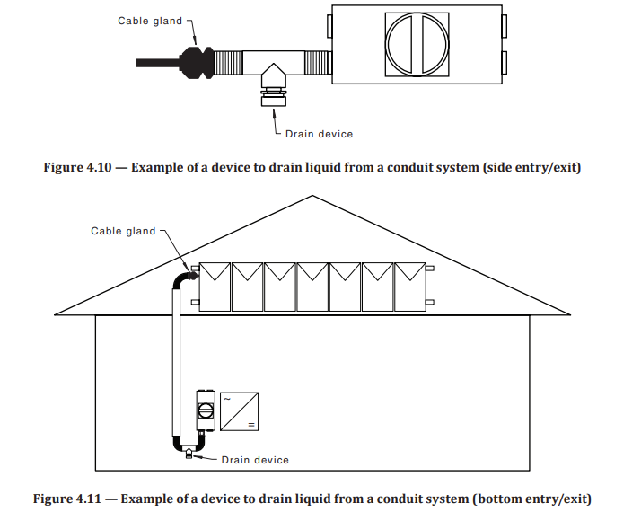
AS/NZS 5033:2021 4.4.7.2.3 Conduits terminating into enclosures containing disconnection devices
Where a continuous conduit system has a section that is in an outdoor environment, and that terminates into an enclosure containing a disconnection device, it shall have a device to drain liquid from the conduit system. This shall be installed at the lowest point of the conduit system and shall be rated to at least IP 56. See Figure 4.10 and Figure 4.11.
Where a continuous conduit system has a section that is in an outdoor environment, and that terminates into an enclosure containing conductor terminations, any open ends of the conduit system shall be sealed with a gland conforming to Clause 4.4.7.2.2.
Where conduits and fittings enter/exit the side face of an enclosure installed in an outdoor location, the entry/exit point into the enclosure containing conductor terminations shall be in accordance with item (i) or item (ii) of Clause 4.4.7.2.2.
NOTE 1 Clause 4.4.6.2 may require pressure equalization devices to be installed in disconnector enclosures. This has a different function to the device to drain liquid from the conduit system.
Where a conduit system has a section that is in an outdoor environment, but the conduit system does not terminate into an enclosure containing a disconnection device, a device to drain liquid may not be required. See Figure 4.7 and Figure 4.8 for
examples of installations where conduit systems do not terminate into enclosures containing disconnection devices. -
Enclosures containing disconnection devices installed in an outdoor environment shall have pressure equalization valves fitted in the enclosure - AS/NZS 5033:2021 4.4.6.2 EXCEPTION — An exception to this requirement is where the pressure equalization valve is integrated into other equipment such as cable glands or drainage devices provided they are installed within 300 mm of the enclosure.
- Compliant
- Non-Compliant
- Not Applicable
- Installer To Confirm/Supply Additional Information
-
AS/NZS 5033:2021 4.4.6.2 Selection of enclosures containing disconnection devices
Enclosures containing disconnection devices shall be selected as specified in Table 4.5.
Enclosures containing disconnection devices installed in an outdoor environment shall have pressure equalization valves fitted in the enclosure.
EXCEPTION — An exception to this requirement is where the pressure equalization valve is integrated into other equipment such as cable glands or drainage devices provided they are installed within 300 mm of the enclosure.
NOTE 1 Where pressure equalization valves are fitted onsite, they should be installed in accordance with manufacturer’s instructions. -
Dedicated individual enclosures containing switch disconnection devices are protected from the effects of weather and water - AS/NZS 5033:2021 4.4.7.3
- Compliant
- Non-Compliant
- Not Applicable
- Installer To Confirm/Supply Additional Information
-
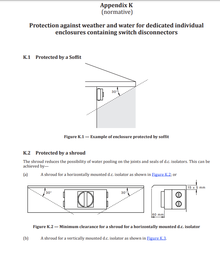
AS/NZS 5033:2021 4.4.7.3 Protection against weather and water for dedicated individual enclosures containing switch disconnectors
Dedicated individual enclosures containing switch disconnection devices shall be protected against the effects of weather and water. Dedicated individual enclosures containing switch disconnection devices are considered to be protected against the effects of weather and water when installed either—
(a) within the space contained by the soffit and a plane from the outer edge of the soffit, at an angle of 30 degrees continuing to the surface that the enclosure is mounted on, see Appendix K Figure K.1; or
(b) within a non-combustible, and mechanically stable shroud resistant to ultraviolet radiation (UV) exposure where the shroud protects the switch disconnectors and meets at least the requirements of Figures K.2 and Figure K.3.
NOTE 1 Shrouds that are resistant to ultraviolet radiation (UV) exposure include shrouds of metal, or material that meet requirements of tests in accordance with Clause 10.2.4 of AS/NZS 61439.1.
NOTE 2 The shroud is used to prevent direct exposure to sunlight over the hottest part of the day and to minimize the chance of water pooling around the isolator seals.
NOTE 3 Consideration should be given to use shrouds over devices other than switch disconnectors. -
Where cable glands, enter/exit the side face of an enclosure installed in an outdoor location they are protected from the effects of weather and water - AS/NZS 5033:2021 4.4.7.2.2
- Compliant
- Non-Compliant
- Not Applicable
- Installer To Confirm/Supply Additional Information
-
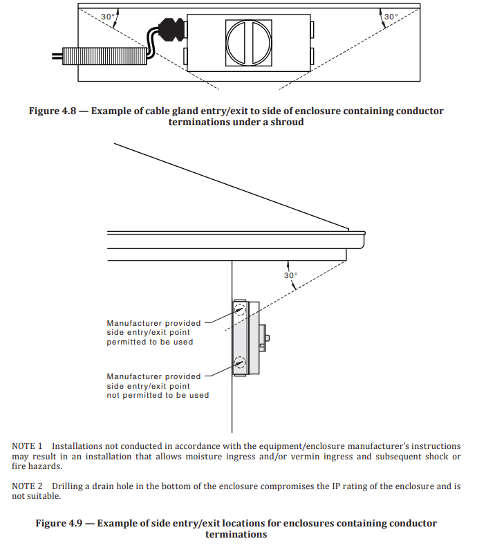
AS/NZS 5033:2021 4.4.7.2.2
Where a cable gland is used in an outdoor environment, the cable gland shall—
(a) be used to enter/exit an enclosure containing conductor terminations;
(b) be installed so that each cable enters/exits through an individual hole;
(c) be rated at least IP 56;
(d) have a hole diameter to maintain IP rating for the cables used (e.g. the diameter of the holes in the cable gland are designed to seal the outside diameter of the cable used); and
(e) have any spare holes sealed with the gland manufacturer’s approved sealing plug.
Cable glands may enter/exit the bottom face of an enclosure containing conductor terminations, see Figure 4.7.
Where cable glands, enter/exit the side face of an enclosure installed in an outdoor location, the entry/exit point into the enclosure containing conductor terminations shall be higher than the lowest point of the wiring system (i.e. to create a drip loop), see Figure 4.7, and—
(i) be within 30 degrees of the space contained by the soffit and the plane from the outer edge of the soffit; or
(ii) be within 30 degrees from the top of the shroud and a plane from the outer edge of the mounting surface, see Figure 4.8 and Figure 4.9.
NOTE 1 Figure 4.8 shows disconnector but the concept applies to all enclosures containing conductor terminations.
NOTE 2 See Clause 4.4.7.2.3 for conduit entry/exit points.
NOTE 3 See Clause 4.4.5.2.2 for requirements of PV d.c. cables at the load break disconnection device
Disconnection point #
-
Disconnection point is protected against weather and water, and no more than 150mm from the edge of the PV modules that they are installed under - AS/NZS 5033:2021 4.3.5.2.1 (c)
- Compliant
- Non-Compliant
- Not Applicable
- Installer To Confirm/Supply Additional Information
-
AS/NZS 5033:2021 4.3.5.2.1
A disconnection point shall be selected in accordance with Clause 4.3.8. It shall meet the installation requirements of Clause 4.3.9. The disconnection point shall also meet the following additional requirements:
(a) Be adjacent to the PV modules of the PV array.
(b) Be readily available.
(c) Be protected against weather and water, and no more than 150mm from the edge of the PV modules that they are installed under.
NOTE 1 Protection against weather and water could be met by installing the disconnection point under a PV module or by means equivalent to Clause 4.4.7.3.
(d) Adequately supported so that there is no undue stress on the connection, but able to be disconnected.
(e) Have both the positive and negative disconnection device located together.
(f) Labelled in accordance with Clause 5.5.2.2.
(g) Documented in accordance with Clause 5.6.
NOTE 2 See Clause 4.4.5.2 for additional requirements of the wiring system -
Disconnection point is adequately supported so that there is no undue stress on the connection, but able to be disconnected - AS/NZS 5033:2021 4.3.5.2.1 (d)
- Compliant
- Non-Compliant
- Not Applicable
- Installer To Confirm/Supply Additional Information
-
AS/NZS 5033:2021 4.3.5.2.1
A disconnection point shall be selected in accordance with Clause 4.3.8. It shall meet the installation requirements of Clause 4.3.9. The disconnection point shall also meet the following additional requirements:
(a) Be adjacent to the PV modules of the PV array.
(b) Be readily available.
(c) Be protected against weather and water, and no more than 150mm from the edge of the PV modules that they are installed under.
NOTE 1 Protection against weather and water could be met by installing the disconnection point under a PV module or by means equivalent to Clause 4.4.7.3.
(d) Adequately supported so that there is no undue stress on the connection, but able to be disconnected.
(e) Have both the positive and negative disconnection device located together.
(f) Labelled in accordance with Clause 5.5.2.2.
(g) Documented in accordance with Clause 5.6.
NOTE 2 See Clause 4.4.5.2 for additional requirements of the wiring system -
Disconnection point has both the positive and negative disconnection device located together - AS/NZS 5033:2021 4.3.5.2.1 (e)
- Compliant
- Non-Compliant
- Not Applicable
- Installer To Confirm/Supply Additional Information
-
AS/NZS 5033:2021 4.3.5.2.1
A disconnection point shall be selected in accordance with Clause 4.3.8. It shall meet the installation requirements of Clause 4.3.9. The disconnection point shall also meet the following additional requirements:
(a) Be adjacent to the PV modules of the PV array.
(b) Be readily available.
(c) Be protected against weather and water, and no more than 150mm from the edge of the PV modules that they are installed under.
NOTE 1 Protection against weather and water could be met by installing the disconnection point under a PV module or by means equivalent to Clause 4.4.7.3.
(d) Adequately supported so that there is no undue stress on the connection, but able to be disconnected.
(e) Have both the positive and negative disconnection device located together.
(f) Labelled in accordance with Clause 5.5.2.2.
(g) Documented in accordance with Clause 5.6.
NOTE 2 See Clause 4.4.5.2 for additional requirements of the wiring system -
A sign containing the following text is attached to both the positive and negative cable within 100 mm of the disconnection point of the PV string: WARNING: LOADS MUST BE ISOLATED AND CIRCUIT MUST BE TESTED FOR THE ABSENCE OF CURRENT BEFORE UNPLUGGING AS/NZS 5033:2021 5.5.2.2
- Compliant
- Non-Compliant
- Not Applicable
- Installer To Confirm/Supply Additional Information
-
AS/NZS 5033:2021 5.5.2.2
A sign containing the following text shall be attached to both the positive and negative cable within 100 mm of the disconnection point of the PV string:
WARNING: LOADS MUST BE ISOLATED AND CIRCUIT MUST BE TESTED FOR THE ABSENCE OF CURRENT BEFORE UNPLUGGING
NOTE 1 See Figure A.4(c).
A sign containing the following text shall be attached to the PV module or structure within 300 mm of the disconnection point to identify the location of the disconnection point:
WARNING: PV STRING DISCONNECTION POINT
NOTE 2 See Figure A.4(d).
The text shall be with a minimum letter size of 10 mm. -
A sign containing the following text is attached to the PV module or structure within 300 mm of the disconnection point to identify the location of the disconnection point: WARNING: PV STRING DISCONNECTION POINT AS/NZS 5033:2021 5.5.2.2
- Compliant
- Non-Compliant
- Not Applicable
- Installer To Confirm/Supply Additional Information
-
AS/NZS 5033:2021 5.5.2.2
A sign containing the following text shall be attached to both the positive and negative cable within 100 mm of the disconnection point of the PV string:
WARNING: LOADS MUST BE ISOLATED AND CIRCUIT MUST BE TESTED FOR THE ABSENCE OF CURRENT BEFORE UNPLUGGING
NOTE 1 See Figure A.4(c).
A sign containing the following text shall be attached to the PV module or structure within 300 mm of the disconnection point to identify the location of the disconnection point:
WARNING: PV STRING DISCONNECTION POINT
NOTE 2 See Figure A.4(d).
The text shall be with a minimum letter size of 10 mm.
Framing
-
Feet spacing are in accordance with manufacturer's guidelines or structual certification. In particular exclusion zones and the use of tilt array
- Compliant
- Non-Compliant
- Not Applicable
- Installer To Confirm/Supply Additional Information
-
The clamping zones of the solar panels are in accordance with the manufacturer's guidelines
- Compliant
- Non-Compliant
- Not Applicable
- Installer To Confirm/Supply Additional Information
-
The equipotential earth conductor has is correctly sized as per 4.6.5 of AS/NZS 5033:2021
- Compliant
- Non-Compliant
- Not Applicable
- Installer To Confirm/Supply Additional Information
-
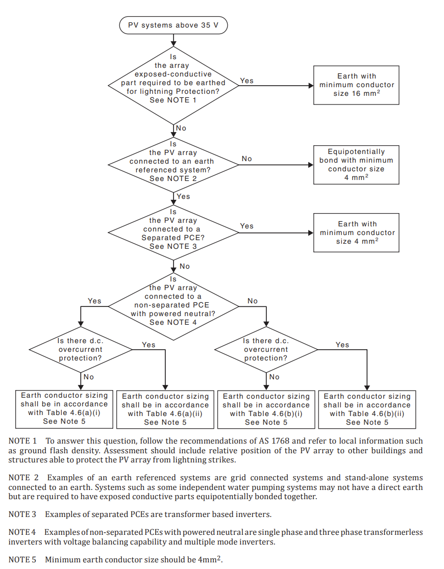
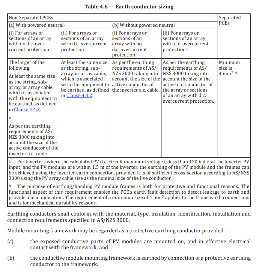
AS/NZS 5033:2021 4.6.5
The cross sectional area of the earthing conductors for the PV array shall:
(a) have a resistance no more than 0.5 Ω between exposed conductive parts and the installation earthing system; and
(b) be in accordance with the Figure 4.13.
All conductor sizes provided in Table 4.6 are based on current-carrying capacity of copper conductors. Where other conductor types are used, those conductors shall have a current-carrying capacity equal to or greater than current-carrying capacity of copper conductor size indicated in Figure 4.13.
Earthing conductors shall conform with the material, type, insulation, identification, installation and connection requirements specified in AS/NZS 3000.
Module mounting framework may be regarded as a protective earthing conductor provided —
(a) the exposed conductive parts of PV modules are mounted on, and in effective electrical contact with the framework; and
(b) the conductive module mounting framework is earthed by connection of a protective earthing conductor to the framework. -
Figure 4.13 — PV array exposed conductive parts earthing or bonding decision tree
-
Table 4.6 — Earth conductor sizing
-
Exposed earth conductors are protected from corosion AS/NZS 3000:2018 5.5.5.3
- Compliant
- Non-Compliant
- Not Applicable
- Installer To Confirm/Supply Additional Information
-
AS/NZS 30000:2018 5.5.5.3 Protection against corrosion
Earthing conductors, and any associated fixing devices, shall be protected from corrosion, including the effects of moisture or contact with dissimilar metals. Earthing conductors and associated fittings and fixing devices shall comply with the following requirements:
(a) Underground and damp situations All joints and terminations installed in an underground location or other damp situation shall be sealed to prevent the entry of moisture. All associated fittings and fixing devices in such locations shall be constructed of, or protected by, corrosionresistant material.
(b) Exposed to the weather All joints, terminations, fittings and fixtures in locations exposed to the weather shall be constructed of, or protected by, corrosion-resistant material in such a manner that will prevent the entry of moisture affecting the conductor. -
Earthing has been connected to array framing by suitable means . AS/NZS 5033:2021 4.6.3
- Compliant
- Non-Compliant
- Not Applicable
- Installer To Confirm/Supply Additional Information
-
AS/NZS 5033:2021 4.6.3
Earthing or bonding connections to PV array frames shall be by any of the following:
(a) A purpose-made fitting providing earthing or bonding connections for dissimilar metals and installed according to the manufacturer’s instructions.
NOTE 1 Some of these fittings are not designed for stranded cable so not all are suitable without the use of a small copper plate to retain cable stands.
(b) Purpose-made washers with serrations or teeth, designed to penetrate the surface for the connection of dissimilar metals between the PV module and mounting frames fitted to the manufacturer’s instructions.
(c) Tinned cable lugs of earthing and bonding cables fixed by stainless steel bolts washers and star washers to aluminium frames.
Self-tapping screws and rivets shall not be used to facilitate earth connections to a PV array framework.
Earthing or bonding connections to PV array frames shall be protected against corrosion.
Purpose-made washers with serrations or teeth, designed to penetrate the surface for the connection of dissimilar metals between the PV module and mounting frames shall be installed at every connection between the PV module and mounting frame or in accordance with manufacturer’s instructions.
The earthing or bonding connections shall be arranged so that the removal of any one PV module will not affect the continuity of the earthing or bonding connections to any other PV module.
NOTE 2 See Clause 4.7.3.2 for testing requirements. -
Care has been taken to reduce contact between dissimilar metals - AS/NZS 5033:2021 4.3.2.2.8
- Compliant
- Non-Compliant
- Not Applicable
- Installer To Confirm/Supply Additional Information
-
AS/NZS 5033:2021 4.3.2.2.8
PV module mounting frames, and the methods used for attaching PV modules to frames and frames to buildings or to the ground, shall be made from corrosion resistant materials suitable for the lifetime and duty of the system (e.g. aluminium, galvanized steel or H3 treated timber).
If the associated roofing or building structure is metallic, then aluminium, stainless steel, hot dipped galvanized steel, wood or polymer materials shall be used.
All framing systems shall be suitable for the location and duty of the system.
NOTE Care should be taken in selecting materials and protection in marine and other corrosive environments.
In coastal areas, the fitting of PV modules to a roof that is exposed to salt laden air may prevent salt deposits from being washed off the roof by rain.
Maintenance instructions as well as roof mounting structure configuration should allow for regular wash down with fresh water.
All bolts, nuts and fasteners shall have appropriate durability for the installed locality. Bolts and nuts should typically be stainless steel.
Care shall be taken to prevent electrochemical corrosion between dissimilar metals. This may occur between structures and the building and between structures, fasteners and PV modules. Stand-off materials shall be used to reduce electrochemical corrosion between galvanically dissimilar metal surfaces (e.g. nylon washers or rubber insulators). Aluminium framing components and stainless fasteners are permitted to be in direct contact (without stand-off materials) as the two metals are
sufficiently galvanically similar. -
Roof penetrations are adequatly sealed and waterproofed using a suitable dektite/flashing NOTE: Grinding a tile and passing the conduit between tile overlaps is not an acceptable method and breaches AS/NZS 3000:2018 clause 3.9.4.3.1. Conduit passing through a hole in a steel roof and then sealed with silicon is in breach of Standards Australia Handbook 39-1997 (clause 8.6).
- Compliant
- Non-Compliant
- Not Applicable
- Installer To Confirm/Supply Additional Information
-
Excess rail has been removed from end of array and ends are even
- Compliant
- Non-Compliant
- Not Applicable
- Installer To Confirm/Supply Additional Information
Wiring
-
DC optimiser have been installed in accordance with manufacturer's specifications
- Compliant
- Non-Compliant
- Not Applicable
- Installer To Confirm/Supply Additional Information
-
All DC cables conform to IEC 62930 where not installed underground - AS/NZS 5033:2021 4.4.2.1
- Compliant
- Non-Compliant
- Not Applicable
- Installer To Confirm/Supply Additional Information
-
AS/NZS 5033:2021 4.4.2.1
The requirements for the selection of cables in this Clause relates to PV d.c. cables. For the selection of earth cables and other cables, refer to AS/NZS 3000.
PV d.c. cables shall:
(a) have a voltage rating greater than or equal to the calculated PV d.c. circuit maximum voltage in accordance with Clause 4.2.1.3—
(i) for all installations, between the positive conductor and negative conductor; and
(ii) for non-separated PCE and functionally earthed installations, between any conductor and earth;
NOTE 1 Examples of cable manufacturers’ methods to specify rating are 0.6/1kVAC 0.9/1.8kVDC. This indicates:
(a) a 600V conductor to earth AC voltage rating and a 1000V conductor to conductor AC voltage
(b) a 900V conductor to earth d.c. voltage rating and a 1800V conductor to conductor d.c. voltage rating
(b) conform to IEC 62930 where not installed underground;
NOTE 2 For cable that installed underground, see Clause 4.4.2.5.
(c) be suitable for d.c. application;
(d) have each conductor double insulated for where the calculated PV d.c. circuit maximum voltage is above 35 V, see Figure 4.4;
NOTE 3 For cables directly terminated to plugs, socket and connectors, see Clause 4.3.8.
(e) have a temperature rating appropriate for the application; and
(f) if exposed to the environment, be UV-resistant, or be protected from UV light by appropriate protection.
NOTE 4 Where installed in buildings, it is recommended that halogen free cables are used i.e. cables qualified to IEC 62930 IEC 131 or IEC 62930 IEC 132.
Cables directly terminated to plugs, socket and connectors as specified in Clause 4.3.8, shall be class 5 (flexible) in accordance with IEC 60228.
NOTE 5 Examples where such cables are required are: string cables; trackers, and where cables are connected using plugs and sockets. Refer to IEC 62738 for more guidance on wire management for trackers.
NOTE 6 For other cables, the conductor of the cable can be class 2 (stranded) or class 5 (flexible) in accordance with IEC 60228. -
Plastic cable ties are not to be used as the primary means of support. AS/NZS 5033:2021 4.3.2.3.1 (g)
- Compliant
- Non-Compliant
- Not Applicable
- Installer To Confirm/Supply Additional Information
-
AS/NZS 5033:2021 4.3.2.3.1
Where wiring of strings between modules or DCUs is not protected by conduit or other enclosures, the following requirements apply:
(a) Insulated and sheathed UV resistant cables shall be used.
(b) Cables shall be selected as specified in Clause 4.4.2.
(c) Cables shall be protected from mechanical damage.
(d) Cables shall be clamped to prevent undue strain on the connections/terminations.
(e) Cables shall not lie on roofs.
(f) Cables shall not obstruct the natural water drain paths or promote accumulation of debris.
(g) The method of cable support and fixing shall have a lifetime greater than or equal to the life of the PV system. Plastic cable ties shall not be used as a primary means of support.
(h) Cables shall be protected against abrasion, tension, compression and cutting forces that may arise from thermal cycles, wind and other forces during installation and throughout the life of the installation.
(i) Cables shall be supported so they do not suffer fatigue due to wind/snow effects.
NOTE 1 Typically, plastic cable ties exposed to UV will degrade within 2 to 5 years.
NOTE 2 Plastic cable ties installed under an array are still exposed to reflected UV radiation.
Where wiring of strings between modules or DCUs is protected by conduit or other enclosures, the requirements of Clause 4.4.5 shall be followed. -
Cable enclosures and conduits on roofs or floors shall not obstruct the natural water drain paths or promote accumulation of debris - AS/NZS 5033:2021 4.4.5.1 (b)
- Compliant
- Non-Compliant
- Not Applicable
- Installer To Confirm/Supply Additional Information
-
AS/NZS 5033:2021 4.4.5.1
The following apply to wiring enclosures containing PV d.c. cables:
(a) Where conduit systems are used, all parts shall be sealed appropriately (by using methods such as glue) unless otherwise stated by the manufacturer.
(b) Cable enclosures and conduits on roofs or floors shall not obstruct the natural water drain paths or promote accumulation of debris.
(c) They shall be marked in accordance with Clause 5.3.1.
(d) Documented in accordance with Clause 5.6.
NOTE 1 Attention should be given to the protection of wiring systems against external influences. Mechanical protection of cables is especially important including penetrations in roofing and walls according to the relevant Standards and codes.
NOTE 2 Where PV d.c. cables are installed in wiring systems near building surfaces (such as those concealed within 50mm from a surface), extra protection methods beyond the requirements of this Clause may be required to meet AS/NZS 3000. -
Where conduit systems are used, all parts shall be sealed appropriately - AS/NZS 5033:2021 4.4.5.1 (a)
- Compliant
- Non-Compliant
- Not Applicable
- Installer To Confirm/Supply Additional Information
-
AS/NZS 5033:2021 4.4.5.1<br><br>The following apply to wiring enclosures containing PV d.c. cables:<br>(a) Where conduit systems are used, all parts shall be sealed appropriately (by using methods such as glue) unless otherwise stated by the manufacturer.<br>(b) Cable enclosures and conduits on roofs or floors shall not obstruct the natural water drain paths or promote accumulation of debris.<br>(c) They shall be marked in accordance with Clause 5.3.1.<br>(d) Documented in accordance with Clause 5.6.<br><br>NOTE 1 Attention should be given to the protection of wiring systems against external influences. Mechanical protection of cables is especially important including penetrations in roofing and walls according to the relevant Standards and codes.<br><br>NOTE 2 Where PV d.c. cables are installed in wiring systems near building surfaces (such as those concealed within 50mm from a surface), extra protection methods beyond the requirements of this Clause may be required to meet AS/NZS 3000.
-
PV DC cables shall not lay on roofs or floors without an enclosure or conduit - AS/NZS 5033:2021 4.4.3.1
- Compliant
- Non-Compliant
- Not Applicable
- Installer To Confirm/Supply Additional Information
-
AS/NZS 5033:2021 4.4.3.1
The requirements for the installation of cables in this Clause relate to PV d.c. cables. For the installation of earth cables, see Clause 4.6.6. For the installation of other cables, refer to AS/NZS 3000.
Cables shall be installed so that they—
(a) meet the requirements of Clause 4.3.2.3 where installed at the PV array;
(b) meet the additional requirements of Clause 4.4.5;
(c) do not lie on roofs or floors without an enclosure or conduit as specified in Clause 4.4.5;
(d) are protected against abrasion, tension, compression and cutting forces that may arise from thermal cycles, wind and other forces during installation and throughout the life of the installation; and
(e) are supported so they do not suffer fatigue due to wind/snow affects.
NOTE Attention should be given to eddy currents when running conductors in metal conduit or trunking. -
Connectors of the same type/model from the same manufacturer mated with those from the same manufacturer and designed to be mated together - AS/NZS 5033:2021 4.3.8 (d)
- Compliant
- Non-Compliant
- Not Applicable
- Installer To Confirm/Supply Additional Information
-
AS/NZS 5033:2021 4.3.8
Plugs, sockets and connectors shall —
(a) be installed to minimize strain on the connectors (e.g. supporting the cable on either side of the connector);
(b) be installed to maintain the IP rating;
(c) be installed on PV d.c. cables conforming to plug, sockets and connector manufacturers’ requirements;
NOTE Plug, sockets and connector manufacturers installation instructions can include requirements relating to torque settings of glands, the outside diameter of the PV cable (including the cable insulation) and the bend radius of the associated cable.
(d) only be mated with those from the same manufacturer and designed to be mated together; and
(e) be terminated using a tool (where required) designed for the purpose and technique specified by the plugs, socket or connector manufacturer’s instructions -
No PVC conduit exposed to direct sunlight - Verdia Spec 5.4.8 (a)
- Compliant
- Non-Compliant
- Not Applicable
- Installer To Confirm/Supply Additional Information
-
Verdia Spec 5.4.8
a) PVC Conduit shall not be exposed to direct sunlight -
All cut edges of galvanised material shall be treated to protect against corrosion e.g. cold gal spray - Verdia Spec 5.4.9 (b)
- Compliant
- Non-Compliant
- Not Applicable
- Installer To Confirm/Supply Additional Information
-
Verdia Spec 5.4.9
b) All cut edges of galvanised material shall be treated to protect against corrosion e.g. cold gal spray. -
Cable trays and ladders shall be fixed and supported with brackets and clamps spaced 50mm minimum from the roof panels. Cable trays and ladders shall not be directly screwed or fixed to roofing under any circumstances. - Verdia Spec 5.4.9 (e)
- Compliant
- Non-Compliant
- Not Applicable
- Installer To Confirm/Supply Additional Information
-
Verdia Spec 5.4.9 e) Cable trays and ladders shall be fixed and supported with brackets and clamps spaced 50mm minimum from the roof panels. Cable trays and ladders shall not be directly screwed or fixed to roofing under any circumstances.
- Compliant
- Non-Compliant
- Not Applicable
- Installer To Confirm/Supply Additional Information
-
Cable trays or cable support systems and their associated fittings are suitable for the enviroment they are installed in eg. Hot dipped gal for external tray
- Compliant
- Non-Compliant
- Not Applicable
- Installer To Confirm/Supply Additional Information
-
Are cable trays adequately bonded and earthed?
- Compliant
- Non-Compliant
- Not Applicable
- Installer To Confirm/Supply Additional Information
-
Pitched cable tray lid has been used on external cable trays if pitch of cable tray is less than 10 degrees - Verdia Spec 5.3.8 (d)
- Compliant
- Non-Compliant
- Not Applicable
- Installer To Confirm/Supply Additional Information
-
Verdia Spec 5.3.8 d) Flat cable tray covers are not permitted for external installation where the slope of the flat cover will be within 10 degrees of horizontal.
- Compliant
- Non-Compliant
- Not Applicable
- Installer To Confirm/Supply Additional Information
-
All cables shall be a continuous run with no joints or extensions acceptable Verdia Spec 5.4.7 (b)
- Compliant
- Non-Compliant
- Not Applicable
- Installer To Confirm/Supply Additional Information
-
Verdia Spec 5.4.7 b) All cables shall be a continuous run with no joints or extensions acceptable.
- Compliant
- Non-Compliant
- Not Applicable
- Installer To Confirm/Supply Additional Information
-
Are conduits fixed with saddles at maximum 1m intervals, with two fixings per saddle - Verdia Spec 5.4.8 (d)(e)
- Compliant
- Non-Compliant
- Not Applicable
- Installer To Confirm/Supply Additional Information
-
Verdia Spec 5.4.8 Conduits and Cable Supports
d) All conduits shall be fixed by two fixings per conduit saddle.
e) Conduit saddles shall be fixed at a maximum of 1 m intervals. -
Cables shall not be supported by catenary wires - Verdia Spec 5.4.8 (c)
- Compliant
- Non-Compliant
- Not Applicable
- Installer To Confirm/Supply Additional Information
-
Verdia Spec - 5.4.8 Conduits and Cable Supports
c) Cables shall not be supported by catenary, regardless of the use of conduit, without the approval of Verdia.
Labels
-
Wiring enclosure has been labelled 'SOLAR' every 2 meters - AS/NZS 5033:2021 5.3.1.1
- Compliant
- Non-Compliant
- Not Applicable
- Installer To Confirm/Supply Additional Information
-
AS/NZS 5033:2021 5.3.1.1
5.3.1.1 General
Where the wiring system containing PV d.c. cables is not installed directly behind and adjacent to the PV modules, it shall be—
(a) identified by distinctive labels marked with the word “SOLAR” on the exterior surface of the wiring system over the length of the enclosure at intervals not exceeding 2 m; and
(b) visible after mounting.
NOTE 1 Where labels are attached directly to PV d.c cables, tags with the words “SOLAR” may be required to meet the sizing guide.
NOTE 2 The background colour and lettering colour on the exterior surface of wiring systems should have appropriate contrast so that it is clearly visible and readable. Any colours that meet the requirement of this clause may be used. -
WARNING: HAZARDOUS d.c. VOLTAGE affixed to junction boxes housing the terminations of PV d.c. cable - AS/NZS 5033:2021 5.3.2
- Compliant
- Non-Compliant
- Not Applicable
- Installer To Confirm/Supply Additional Information
-
AS/NZS 5033:2021 5.3.2 Signs for junction boxes containing PV d.c. cable terminations
A warning label containing the warning symbol and stating the following shall be attached to junction boxes housing the terminations of PV d.c. cable:
WARNING: HAZARDOUS d.c. VOLTAGE
NOTE 1 See Figure A.2.
NOTE 2 This does not apply to PV array disconnecting devices as they have their own labelling requirements (see Clause 5.5.2). -
PV ARRAY d.c. ISOLATOR affixed to load break disconnection devices - AS/NZS 5033:2021 5.5.2.1
- Compliant
- Non-Compliant
- Not Applicable
- Installer To Confirm/Supply Additional Information
-
AS/NZS 5033:2021 5.5.2.1 Load break disconnection device
Load break disconnectors shall be provided with a sign affixed in a prominent location with the following text:
PV ARRAY d.c. ISOLATOR
NOTE See Figure A.4(a).
Where multiple isolation/disconnection devices are used that are not ganged (see Clause 4.5.4.2) the following sign shall be fixed adjacent to the PCE and have a warning label containing a warning symbol and stating:
WARNING: MULTIPLE d.c. SOURCES
TURN OFF ALL d.c. ISOLATORS TO ISOLATE EQUIPMENT
NOTE See Figure A.4(b). -
Load break disconnection devices marked with an identification name or number consistent with terminology used in the shutdown procedure - AS/NZS 5033:2021 5.5.1
- Compliant
- Non-Compliant
- Not Applicable
- Installer To Confirm/Supply Additional Information
-
AS/NZS 5033:2021 5.5.1 General
Load break disconnection devices shall be marked with an identification name or number consistent with terminology used in the shutdown procedure.
All switches shall clearly and reliably indicate the isolating position of the device.
NOTE The symbols “O” (off) and “I” (on) are deemed to satisfy this requirement. -
Fuse holders shall have a warning label to not withdraw fuse under load - AS/NZS 5033:2021 5.8
- Compliant
- Non-Compliant
- Not Applicable
- Installer To Confirm/Supply Additional Information
-
AS/NZS 5033:2021 5.8
Fuse holders shall have a warning label to not withdraw fuse under load. -
All labels installed are indelible and sufficiently durable for the intended purpose (UV resistant and indelible) - AS/NZS 5033:2021 5.2.1 (f)
- Compliant
- Non-Compliant
- Not Applicable
- Installer To Confirm/Supply Additional Information
-
5.2 REQUIREMENTS FOR LABELS AND SIGNS
5.2.1 General
All labels and signs required shall be —
(a) durable and designed to have a lifetime greater than or equal to the service life of the PV system;
(b) constructed of appropriate materials suitable for the location;
(c) fixed in a manner appropriate for the location;
(d) in English;
(e) legible and the letter size to be appropriate for the location (see Note 1);
(f) indelible;
(g) visible where applicable (e.g. some signs may be enclosed in a switchboard cabinet, but visible when an operator opens the switchboard to perform maintenance or emergency services); and
(h) where installed exposed to direct sunlight conform to Clause 5.2.2.
NOTE 1 Sign lettering should be sized with uppercase lettering of 5 mm high and lowercase of 4 mm high per metre of viewing distance, unless otherwise specified.
NOTE 2 As a guide, the background colour and lettering colour should follow the principles listed below:
(a) Signs for general information should be white with black lettering.
(b) Signs for the essential safety of service personnel should be yellow with black lettering with a warning symbol.
(c) Signs for attention of emergency personnel should be red with white lettering.
(d) Special signs may use other colours.
5.2.2 UV resistance
Labels/signs exposed to direct sunlight shall be UV resistant. -
Where cable trays cross over a walkway or access route the words “NO STEP”, and edges shall be paint so they are visible - Verdia Spec 5.4.9 (g)
- Compliant
- Non-Compliant
- Not Applicable
- Installer To Confirm/Supply Additional Information
-
Verdia Spec - 5.4.9 Cable Ladders and Trays<br><br>g) Where cable trays cross over a walkway or access route (e.g. between rows of PV modules), mark the cover with the words “NO STEP”, and paint/mark the edges of the cover to make them highly visible.
Additional defects or issues
-
Are there any other issues or defects present
Additional defects or issues
-
undefined
-
Add media
Additional Information
-
Additional Photos
-
Additional Information
Roof Space
-
Have 'Disconnection points' been used?
-
-
-
Is there wiring system located outside of the restricted zone AS/NZS 5033:2021 4.4.5.2.3
- Compliant
- Non-Compliant
- Not Applicable
- Installer To Confirm/Supply Additional Information
-
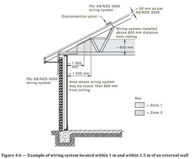
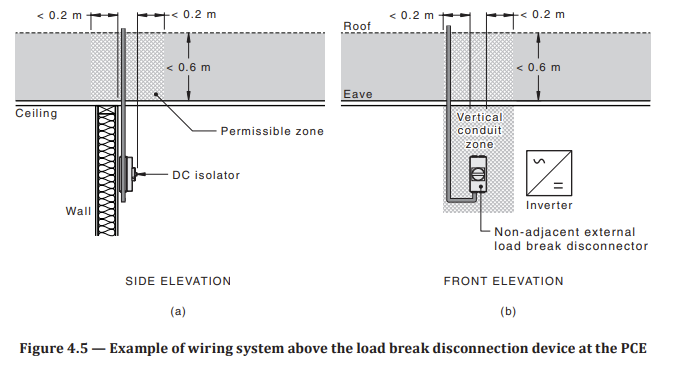
AS/NZS 5033:2021 4.4.5.2.3
4.4.5.2.3 Wiring systems between disconnection point and load break disconnection device or an application circuit
Wiring systems installed within a ceiling space shall not be located within 0.6 m above the surface of the ceiling unless—
(a) the wiring system is located within 1 m from the internal surface of the external wall, see Zone 1 in Figure 4.6;
(b) the wiring system is located within 1 m to 1.5 m from the internal surface of an external wall, and it is attached to roof structure, see Zone 2 in Figure 4.6; or
(c) the wiring system is located within a vertical plane that extends 0.2 m from the external edge of the load break disconnection device at the PCE or the application circuit, see vertical conduit zone in Figure 4.5.
Where the ceiling space is not greater than 0.6 m in height wiring systems shall not be in the ceiling space unless the wiring system is located within 1 m from the internal surface of the external wall, see Figure 4.6.
NOTE 1 To install a wiring system within a ceiling space that is not greater than 0.6 m in height, a PV isolation method that uses a load break disconnection device may be used.
NOTE 2 These requirements are to prevent the cables from collapsing below the ceiling in the event of a ceiling collapse.
Where wiring systems are installed within buildings, additional mechanical protection is required, see Clause 4.4.5.2.2. Wiring systems installed within a ceiling space shall be secured to prevent inadvertent dislodgement from conduit support. Wiring systems installed within a ceiling space shall not be fixed in a position within 50 mm from the underside of the roofing material. -
A warning label is installed adjacent to the access point containing the warning symbol and stating the following: "WARNING: HAZARDOUS d.c. VOLTAGE Solar d.c. cables in conduit have been installed in this ceiling space. The conduit is labelled ‘SOLAR’ and care must be taken while working nearby. The internal solar d.c. cables may be live and must not be disturbed or damaged" AS/NZS 5033:2021 5.3.1.2
- Compliant
- Non-Compliant
- Not Applicable
- Installer To Confirm/Supply Additional Information
-
AS/NZS 5033:2021 5.3.1.2 - In a ceiling space or accessible floor space
Where PV d.c. wiring systems between the disconnection point and a load break disconnection device are installed in an accessible ceiling space or within an accessible floor space, a warning label shall be installed adjacent to the access point containing the warning symbol and stating the following:
WARNING: HAZARDOUS d.c. VOLTAGE
Solar d.c. cables in conduit have been installed in this ceiling space. The conduit is labelled ‘SOLAR’ and care must be taken while working nearby. The internal solar d.c. cables may be live and must not be disturbed or damaged.
NOTE 1 The yellow warning can be separate but added above the information sign so as to simplify sign manufacturing.
The text shall be with a minimum letter size of 10 mm.
NOTE 2 See Figure A.1. -
Cables shall be supported at suitable intervals to prevent the undue sagging of cables - AS/NZS 3000:2018 3.9.3.3
- Compliant
- Non-Compliant
- Not Applicable
- Installer To Confirm/Supply Additional Information
-
AS/NZS 3000:2018 3.9.3.3
Wiring systems likely to be disturbed
Wiring systems installed in the following locations are deemed likely to be disturbed and shall be supported at suitable intervals to prevent the undue sagging of cables:
(a) On the surface of a wall or on the underside of a ceiling or roof.
(b) In a space between a floor and the ground to which a person may gain entry.
(c) In a ceiling space having an access space exceeding 0.6 m high.
(d) Within two metres of any access to any space to which a person may gain entry.
(e) Below raised floors -
Are conduits fixed with saddles at maximum 1m intervals, with two fixings per saddle - Verdia Spec 5.4.8 (d)(e)
- Compliant
- Non-Compliant
- Not Applicable
- Installer To Confirm/Supply Additional Information
-
Verdia Spec 5.4.8 Conduits and Cable Supports
d) All conduits shall be fixed by two fixings per conduit saddle.
e) Conduit saddles shall be fixed at a maximum of 1 m intervals. -
Cables shall not be supported by catenary wires - Verdia Spec 5.4.8 (c)
- Compliant
- Non-Compliant
- Not Applicable
- Installer To Confirm/Supply Additional Information
-
Verdia Spec - 5.4.8 Conduits and Cable Supports
c) Cables shall not be supported by catenary, regardless of the use of conduit, without the approval of Verdia.
Labels
-
Wiring enclosure has been labelled 'SOLAR' every 2 meters - AS/NZS 5033:2021 5.3.1.1
- Compliant
- Non-Compliant
- Not Applicable
- Installer To Confirm/Supply Additional Information
Additional defects or issues
-
Are there any other issues or defects present
Additional defects or issues
-
undefined
-
Add media
Additional Information
-
Additional Photos
-
Additional Information
PVDB
Photos
-
Photos of PVDB
PVDB
-
Is the correct rated circuit breaker been installed as per the SLD
- Compliant
- Non-Compliant
- Not Applicable
- Installer To Confirm/Supply Additional Information
-
Are cables installed of the correct size in accordance with AS/NZS 3008 and the SLD
- Compliant
- Non-Compliant
- Not Applicable
- Installer To Confirm/Supply Additional Information
-
Terminals correctly tightened as per manufactures specifications
- Compliant
- Non-Compliant
- Not Applicable
- Installer To Confirm/Supply Additional Information
-
All items installed correctly and securely
- Compliant
- Non-Compliant
- Not Applicable
- Installer To Confirm/Supply Additional Information
-
PVDB is correctly rated for the location it is installed in and IP rating has been maintained
- Compliant
- Non-Compliant
- Not Applicable
- Installer To Confirm/Supply Additional Information
-
PVDB has not been installed in a restricted location - AS/NZS 3000:2018 2.10.2.5
- Compliant
- Non-Compliant
- Not Applicable
- Installer To Confirm/Supply Additional Information
-
AS/NZS 3000:2018 2.10.2.5
2.10.2.5 Restricted locations
Restricted locations for switchboards are as follows:
(a) Height above ground, floor or a platform A switchboard shall not be located within 1.2 m of the ground, floor or platform.
Exception: A switchboard may be located within 1.2 m of the ground, floor or a platform if access to live parts is arranged, in accordance with the requirements of Clause 2.10.3.1.
(b) Water containers and fixed or stationary cooking appliances A switchboard shall not be installed above open water containers or fixed or stationary cooking appliances.
NOTE: Refer to Item (d) below for baths and showers.
Exception: A switchboard may be located in an area that may be affected by water splashing or by steam, provided that the switchboard is provided with a suitable enclosure or is installed in a cupboard with close-fitting doors.
(c) In cupboards A switchboard installed in a cupboard or similar enclosure shall only be installed in an area set aside for the purpose. The provisions of Clause 2.10.2.2 require that the switchboard be
designed and located to provide readily available access for the purposes of operation and maintenance of equipment mounted on the switchboard. The following restrictions apply to all switchboards.
The switchboard shall be—
(i) installed in a section of the cupboard separated from other sections;
(ii) installed at the front of the switchboard section of the cupboard;
(iii) facing the cupboard access door with insufficient unused space between the switchboard and the cupboard door, when closed, to store extraneous objects in front of the switchboard; and
(iv) arranged so that below the area of the switchboard panel or enclosure, there are no projections that obstruct access for the operation and maintenance of the switchboard.
(d) Near baths and showers A switchboard shall not be installed within any zone classified in accordance with Clause 6.2.2 for a bath or shower.
NOTE: Areas in the proximity of a shower are deemed unsuitable for switchboards because of the prevalence of high humidity and condensation.
(e) Near swimming pools, spas or saunas A switchboard shall not be installed within or above any zone classified in accordance with Clause 6.3.2 for a swimming pool or spa pool.
A switchboard shall not be installed within a sauna.
(f) Refrigeration rooms A switchboard shall not be installed within a refrigeration room.
(g) Sanitization or general hosing-down operations Switchboards installed in classified zones in locations subject to sanitization or hosing-down operations shall be provided with a minimum degree of protection of IPX6.
(h) Fire exits and egress paths Switchboards shall be located or arranged to minimize the impact of any smoke generated from a fault in the switchboard affecting egress from the building.
A switchboard shall not be installed within a fire-isolated stairway, passage way or ramp.
A switchboard may be installed within a cupboard, or similar compartment, in other forms of required exit, or in any corridor, hallway, lobby or the like leading to such an exit, provided that the cupboard or compartment doors are sealed against the spread of smoke from the switchboard.
NOTES:
1 The compartment may be the switchboard enclosure, provided that the enclosure provides a seal to the ingress of dust to at least IP5X and is provided with a facility to be kept locked in normal service.
2 These restrictions are based on the provisions of national building codes to which reference should be made for definition of the terms and for exceptions that may apply.
(i) Near fire-hose reels A switchboard shall not be installed within a cupboard containing a fire-hose reel.
NOTE: Information on the installation of fire hydrants and fire-hose reels in buildings is given in national building codes and the AS 2419 series, or NZS 4510 and AS 2441.
(j) Near automatic fire-sprinklers The following types of switchboards shall not be installed in the vicinity of an automatic fire-sprinkler system:
(i) Main switchboards.
(ii) Switchboards from which safety services originate in accordance with Clause 7.2.
Exception: A switchboard may be installed in the vicinity of an automatic fire sprinkler system if at least one of the following conditions is satisfied:
(i) The switchboard is provided with degree of protection IPX4, in accordance with AS 60529.
(ii) The switchboard is provided with a shield to prevent water spraying on it.
(iii) Sprinkler heads that could project water on the switchboard are provided with suitable deflectors.
(iv) Sprinkler heads are of the dry type.
(k) Hazardous areas Switchboards shall not be installed in hazardous areas as defined in AS/NZS 60079.10.1 or AS/NZS 60079.10.2.
Exception: Switchboards constructed in accordance with AS/NZS 60079.14 may be installed within a hazardous area for which they are specifically designed.
NOTES:
1 The following situations may give rise to a hazardous area:
(a) Heavier-than-air bottled flammable gas cylinders with an aggregate gas capacity exceeding 30 m3 [e.g. liquid petroleum gas (LPG)].
(b) Gas-tank filling or discharge connections.
(c) Pressure relief device discharge points fitted to gas installations.
2 Refer to AS/NZS 60079.10.1 for information regarding hazardous areas.
3 An example of the hazardous area/exclusion zone surrounding heavier than-air gas cylinder is shown in Figure 4.18.
4 In New Zealand only, an example of the hazardous area/exclusion zone surrounding a reticulated (natural) gas system regulator is shown in
Figure 4.20. -
All unused conductors have been terminated correctly AS/NZS 3000:2018 1.5.11.4
- Compliant
- Non-Compliant
- Not Applicable
- Installer To Confirm/Supply Additional Information
-
1.5.11.4 Voltage in unused conductors Protection shall be provided against injury or property damage because of any harmful effects of voltage that may be induced or otherwise occur in unused conductors. Disconnected, redundant or unused conductors associated with conductors that remain connected shall be terminated and protected at both ends in the same manner as is required for live conductors. NOTE: Such conductors are capable of attaining induced, unwanted voltages that may be dangerous, particularly where in close proximity to high voltage conductors.
- Compliant
- Non-Compliant
- Not Applicable
- Installer To Confirm/Supply Additional Information
-
Have cables been correctly terminated to prevent the spreading or escape of individual strands - AS/NZS 3000:2018 3.7.2.5 'Shall'
- Compliant
- Non-Compliant
- Not Applicable
- Installer To Confirm/Supply Additional Information
-
AS/NZS 3000:2018 3.7.2.5 Retention of stranded conductors
The ends of stranded conductors shall be secured by suitable means, so as to prevent the spreading or escape of individual strands. They shall not be soft-soldered before clamping under a screw or between metal surfaces. -
The insulation has not been exposed any more than necessary to terminate the cable AS/NZS 3000:2018 3.7.2.2 'Shall'
- Compliant
- Non-Compliant
- Not Applicable
- Installer To Confirm/Supply Additional Information
-
AS/NZS 3000:2018 3.7.2.2 Preparation for connection
The insulation on a conductor shall not be removed any further than is necessary to make the connection.
For connections between insulated conductors, the connection shall be insulated to provide a degree of insulation not inferior to that of the conductors. Any damaged insulation shall be reinstated. -
Precations have been made to limit circulations and eddy currents on the cable entering the switchboard AS/NZS 3000:2018 3.9.10.2
- Compliant
- Non-Compliant
- Not Applicable
- Installer To Confirm/Supply Additional Information
-
3.9.10.2 Cables for a.c. circuits—Electromagnetic effects
Single-core cables armoured with steel wire or tape shall not be used for a.c. circuits.
Conductors of a.c. circuits installed in ferromagnetic enclosures shall be arranged so that the conductors of all phases and the neutral conductor (if any) and the appropriate protective earthing conductor of each circuit are contained in the same enclosure.
Where such conductors enter a ferrous enclosure they shall be—
(a) arranged so that the conductors are not individually surrounded by a ferrous material; or
(b) provided with other means of limiting any excessive heating effects of eddy (induced) currents.
NOTES:
1 Particular care needs to be taken where single-core cables carrying current in excess of 300 A pass through ferrous metal wall lining, switchboard surrounds, or similar ferrous enclosures.
2 The use of non-ferrous enclosures or gland plates or, where suitable, providing an air gap by slotting between individual core entries to break the magnetic circuit may be applied to eliminate this effect. A slot between individual core entries with a width of 20% of the individual core entries diameter is considered satisfactory. -
Penetrations into switchboard are suitably sealed against the spread of fire . AS/NZS 3000:2018 2.10.7
- Compliant
- Non-Compliant
- Not Applicable
- Installer To Confirm/Supply Additional Information
-
2.10.7 Fire-protective measures
Wiring associated with switchboards shall be installed in such a manner that, in the event of fire originating at the switchboard, the spread of fire will be kept to a minimum.
Where a switchboard is enclosed in a case or surround, any wiring systems entering the switchboard enclosure shall pass through openings that provide a close fit.
NOTES:
1 See also Clause 2.10.2.5(h) regarding restricted location of switchboards in or near egress paths or fire exits and Clause 3.9.9 regarding requirements to prevent the spread of fire.
2 There is a very high risk that wiring enclosures, especially those that enter at the top or sides of a switchboard, will contribute to the spread of fire and for this reason care needs to be taken to ensure that these wiring systems are provided with close-fitting entries. In some cases internal sealing should be provided.
3 An opening with less than 5 mm diameter of free space is considered to be a close fit. Therefore, any opening of 5 mm diameter or greater requires sealing with a fire-retardant sealant.
4 Wiring enclosures, such as conduits, having an internal free space of greater than 5 mm diameter also require sealing to stop any draft effect that could allow the spread of fire -
Low voltage and extra low voltage conductors have been suitable segregated - AS/NZS 3000:2018 3.9.8.3 Segregation of different voltage levels
- Compliant
- Non-Compliant
- Not Applicable
- Installer To Confirm/Supply Additional Information
-
AS/NZS 3000:2018 3.9.8.3 Segregation of different voltage levels
Cables of high voltage circuits and cables of low or extra-low voltage circuits shall not be enclosed in the same wiring system. Cables of low voltage circuits and cables of extra-low voltage circuits shall only be enclosed in the same wiring system where one of the following arrangements is employed:
(a) The low voltage cables are of a type providing the equivalent of double insulation.
(b) All cables or each conductor of a multi-core cable are insulated for the highest voltage present.
(c) The low voltage cables are installed in a separate compartment of a common cable trunking system having fixed and ontinuous barriers between compartments. -
Does the MAIN SWITCH (INVERTER SUPPLY) isolate the correct inverter? (operate it to check)
- Compliant
- Non-Compliant
- Not Applicable
- Installer To Confirm/Supply Additional Information
Labels
-
All main switches have been labelled – AS4777.1:2016 6.2(b)(c)(d), AS/NZS 3000:2018 2.3.3.5 (a)(b)
- Compliant
- Non-Compliant
- Not Applicable
- Installer To Confirm/Supply Additional Information
-
AS4777.1:2016 6.2 SIGNS FOR THE SWITCHBOARD TO WHICH THE IES IS DIRECTLY CONNECTED
The following signs shall be installed on the switchboard to which the IES is directly connected:
(b) A sign containing the text ‘MAIN SWITCH (INVERTER SUPPLY)’. This sign shall be installed adjacent to the main switch for the IES.
(c) Where the inverter is connected to the main switchboard, a sign containing the text ‘MAIN SWITCH (GRID SUPPLY)’. This sign shall be installed adjacent to the main switch(es) for the grid supply.
(d) Where the inverter is connected to a distribution switchboard, a sign containing the text ‘MAIN ISOLATOR (NORMAL SUPPLY)’. This sign shall be installed adjacent to the isolator(s) for the normal supply to the distribution switchboard.
NOTE: In some areas, alternate words may be used for ‘grid supply’ to indicate the mains supply or the supply from the electricity distributor; acceptable alternatives that can be used for ‘grid supply’ include ‘mains supply’ and ‘normal supply’.
AS/NZS 3000:2018 2.3.3.5
2.3.3.5 Identification
Main switches shall be identified as follows:
(a) Each main switch shall be marked ‘MAIN SWITCH’ and shall be readily distinguishable from other switchgear by means of grouping, contrasting colouring or other suitable means to provide for prompt operation in an emergency.
(b) Where there is more than one main switch, each main switch shall be marked to indicate the electrical installation or portion of the electrical installation it controls. -
Warning Multiple Supplies label installed at PVDB - AS 4777.1:2016 6.2 (a), 6.3
- Compliant
- Non-Compliant
- Not Applicable
- Installer To Confirm/Supply Additional Information
-
AS 4777.1:2016 6.2 SIGNS FOR THE SWITCHBOARD TO WHICH THE IES IS DIRECTLY CONNECTED
The following signs shall be installed on the switchboard to which the IES is directly connected:
(a) A sign containing the text ‘WARNING’, ‘MULTIPLE SUPPLIES’ and ‘ISOLATE ALL SUPPLIES BEFORE WORKING ON THIS SWITCHBOARD’. This sign shall be installed in a prominent position on the switchboard.
6.3 SIGNS FOR OTHER SWITCHBOARDS
Where the IES is directly connected to a distribution switchboard, signs shall be installed in prominent positions on the main switchboard and all intermediate distribution switchboards. These signs shall contain the text ‘WARNING’, ‘MULTIPLE SUPPLIES’ and ‘ISOLATE INVERTER SUPPLY AT DISTRIBUTION SWITCHBOARD’ and ‘LOCATION’ where ‘LOCATION’ refers to the physical location of the switchboard that the IES is directly connected to. -
All labels installed are indelible and sufficiently durable for the intended purpose (UV resistant and indelible) - AS/NZS 5033:2021 5.2.1 (f)
- Compliant
- Non-Compliant
- Not Applicable
- Installer To Confirm/Supply Additional Information
-
5.2 REQUIREMENTS FOR LABELS AND SIGNS
5.2.1 General
All labels and signs required shall be —
(a) durable and designed to have a lifetime greater than or equal to the service life of the PV system;
(b) constructed of appropriate materials suitable for the location;
(c) fixed in a manner appropriate for the location;
(d) in English;
(e) legible and the letter size to be appropriate for the location (see Note 1);
(f) indelible;
(g) visible where applicable (e.g. some signs may be enclosed in a switchboard cabinet, but visible when an operator opens the switchboard to perform maintenance or emergency services); and
(h) where installed exposed to direct sunlight conform to Clause 5.2.2.
NOTE 1 Sign lettering should be sized with uppercase lettering of 5 mm high and lowercase of 4 mm high per metre of viewing distance, unless otherwise specified.
NOTE 2 As a guide, the background colour and lettering colour should follow the principles listed below:
(a) Signs for general information should be white with black lettering.
(b) Signs for the essential safety of service personnel should be yellow with black lettering with a warning symbol.
(c) Signs for attention of emergency personnel should be red with white lettering.
(d) Special signs may use other colours.
5.2.2 UV resistance
Labels/signs exposed to direct sunlight shall be UV resistant. -
Have laminated drawings been left inside the PVDB - Verdia Spec 5.6.6 (e)
- Compliant
- Non-Compliant
- Not Applicable
- Installer To Confirm/Supply Additional Information
-
Verdia Spec 5.6.6
e) A laminated copy of the single line diagram and start-up and shut-down instructions shall be installed in all PV Distribution Boards, at the customer’s main switch board, and at all intermediate distribution boards.
Additional defects or issues
-
Are there any other issues or defects present
Additional defects or issues
-
undefined
-
Add media
Additional Information
-
Additional Photos
-
Additional Information
Inverters
Photos
-
Inverter
-
Serial Number of inverters
Inverter
-
Are all the inverters the same make/model and rating as specified in the most recent approved drawings?
- Compliant
- Non-Compliant
- Not Applicable
- Installer To Confirm/Supply Additional Information
-
For non-domestic installations where the maximum d.c. voltages exceed 600 V, the entire d.c. installation and associated wiring and protection shall have restricted access AS/NZS 4777.1:2016 2.3
- Compliant
- Non-Compliant
- Not Applicable
- Installer To Confirm/Supply Additional Information
-
AS/NZS 4777.1:2016 2.3 GENERAL REQUIREMENTS FOR INVERTER ENERGY SYSTEMS (IES)
An IES installation is made up of an inverter(s), an energy source(s), wiring, and control, monitoring and protection devices connected at a single point in an electrical installation. Multiple IES installations can exist within a single electrical installation.
Unless specifically stated by the electricity distributor, the rating limit for a single-phase IES in an individual installation shall be equal to 5 kVA, and a multi-phase IES shall have a balanced output with respect to its rating with a tolerance of no greater than 5 kVA unbalance between any phases.
Installations in domestic dwellings shall not have maximum d.c. voltages that span greater than 600 V. For non-domestic installations where the maximum d.c. voltages exceed 600 V, the entire d.c. installation and associated wiring and protection shall have restricted access. For non-domestic installations, at the inverter where the d.c. voltage exceeds 600 V d.c., restricted access is satisfied where the cabling is in heavy duty conduit or is fully enclosed in an equivalent electrical enclosure that is not accessible without the use of a tool up to and including the inverter d.c. port. If in accessible areas, the associated protection and isolation devices shall also be fully enclosed and only accessible with the use of a tool.
The size, balancing of current output (for multi-phase installations) and voltage rise should be considered in the design of IES.
NOTE: See Appendix C for design considerations.
The inverter(s) shall comply with the requirements of AS/NZS 4777.2 to ensure safe operation when connected to any consumer installation supplied from a grid. Additional protective functions, earth fault and overcurrent protection shall be in accordance with the requirements of this Standard.
The IES shall be installed in accordance with the requirements of this Standard, and those of the IES component manufacturers. Where there is a conflict, this Standard shall prevail.
NOTE: The attention of system designers and installers is drawn to the requirements detailed in the manual provided with the inverter relating to the installation of external RCDs and other devices externally mounted as required by AS/NZS 4777.2 or IEC 62109-1 and IEC 62109-2. Externally mounted RCDs, earth leakage detection devices and/or interruption devices may be required. Demand response enabling devices for inverter control may be available for connection. Inverter manufacturers may also have specific connection requirements related to inverter topology, such as non-separated supplies.
Where the IES does not provide a metered output and the revenue metering of the electricity distributor does not provide direct IES output metering, an energy (kilowatt hour) meter or other logging device to record the output of the IES should be installed. -
Inverter/s installed as per manufactures specification. 'Shall' AS/NZS 3000:2018 1.7.1 (c)
- Compliant
- Non-Compliant
- Not Applicable
- Installer To Confirm/Supply Additional Information
-
AS/NZS 3000:2018 1.7.1 (c)
(c) electrical equipment shall be installed in accordance with the requirements of this Standard and the additional requirements as specified in the manufacturer’s instructions. -
Glands and seals installed where required to maintain Ip Rating
- Compliant
- Non-Compliant
- Not Applicable
- Installer To Confirm/Supply Additional Information
-
Cover Screws tightened
- Compliant
- Non-Compliant
- Not Applicable
- Installer To Confirm/Supply Additional Information
-
Earth fault alarm present or monitoring for system has been configured - AS/NZS 5033:2021 3.5.3
- Compliant
- Non-Compliant
- Not Applicable
- Installer To Confirm/Supply Additional Information
-
AS/NZS 5033:2021 3.5.3 Earth fault alarm
Where the calculated PV d.c. circuit maximum voltage is above 120 V or the PV array is connected to a non-separated inverter conforming to IEC 62109-2, an earth fault alarm system shall be installed.
The alarm system shall continue repeating its operation at least at hourly intervals until the earth fault is corrected or until the fault is acknowledged.
The earth fault alarm shall be at least one of the following types:
(a) Remote communication (such as email, SMS or similar).
(b) Local indication.
Where local indication is used for the earth fault alarm, it shall be either an audible or visual signal placed in an area that will be noticed.
A set of operational instructions shall be provided that includes the actions to take when the alarm operates.
NOTE Many inverters have earth fault detection and indication, in the form of indicator lights. This indication is generally not in an area that will be noticed. IEC 62109-2 requires that inverters have a local indication and a means of signalling an earth fault externally. The external alarm function should be used to cause an action to be initiated to correct the earth fault (i.e. by placing a light or audible signal where it will be noticed). -
The inverter has not been installed in a restricted location as per AS/NZS 3000:2018 and AS/NZS4777.1:2016
- Compliant
- Non-Compliant
- Not Applicable
- Installer To Confirm/Supply Additional Information
-
AS/NZS 4777.1:2016 5.3.1
The inverter shall not be located in a restricted location as defined for switchboards in AS/NZS 3000.
AS/NZS 3000:2018 2.10.2.5
2.10.2.5 Restricted locations
Restricted locations for switchboards are as follows:
(a) Height above ground, floor or a platform A switchboard shall not be located within 1.2 m of the ground, floor or platform.
Exception: A switchboard may be located within 1.2 m of the ground, floor or a platform if access to live parts is arranged, in accordance with the requirements of Clause 2.10.3.1.
(b) Water containers and fixed or stationary cooking appliances A switchboard shall not be installed above open water containers or fixed or stationary cooking appliances.
NOTE: Refer to Item (d) below for baths and showers.
Exception: A switchboard may be located in an area that may be affected by water splashing or by steam, provided that the switchboard is provided with a suitable enclosure or is installed in a cupboard with close-fitting doors.
(c) In cupboards A switchboard installed in a cupboard or similar enclosure shall only be installed in an area set aside for the purpose. The provisions of Clause 2.10.2.2 require that the switchboard be
designed and located to provide readily available access for the purposes of operation and maintenance of equipment mounted on the switchboard. The following restrictions apply to all switchboards.
The switchboard shall be—
(i) installed in a section of the cupboard separated from other sections;
(ii) installed at the front of the switchboard section of the cupboard;
(iii) facing the cupboard access door with insufficient unused space between the switchboard and the cupboard door, when closed, to store extraneous objects in front of the switchboard; and
(iv) arranged so that below the area of the switchboard panel or enclosure, there are no projections that obstruct access for the operation and maintenance of the switchboard.
(d) Near baths and showers A switchboard shall not be installed within any zone classified in accordance with Clause 6.2.2 for a bath or shower.
NOTE: Areas in the proximity of a shower are deemed unsuitable for switchboards because of the prevalence of high humidity and condensation.
(e) Near swimming pools, spas or saunas A switchboard shall not be installed within or above any zone classified in accordance with Clause 6.3.2 for a swimming pool or spa pool.
A switchboard shall not be installed within a sauna.
(f) Refrigeration rooms A switchboard shall not be installed within a refrigeration room.
(g) Sanitization or general hosing-down operations Switchboards installed in classified zones in locations subject to sanitization or hosing-down operations shall be provided with a minimum degree of protection of IPX6.
(h) Fire exits and egress paths Switchboards shall be located or arranged to minimize the impact of any smoke generated from a fault in the switchboard affecting egress from the building.
A switchboard shall not be installed within a fire-isolated stairway, passage way or ramp.
A switchboard may be installed within a cupboard, or similar compartment, in other forms of required exit, or in any corridor, hallway, lobby or the like leading to such an exit, provided that the cupboard or compartment doors are sealed against the spread of smoke from the switchboard.
NOTES:
1 The compartment may be the switchboard enclosure, provided that the enclosure provides a seal to the ingress of dust to at least IP5X and is provided with a facility to be kept locked in normal service.
2 These restrictions are based on the provisions of national building codes to which reference should be made for definition of the terms and for exceptions that may apply.
(i) Near fire-hose reels A switchboard shall not be installed within a cupboard containing a fire-hose reel.
NOTE: Information on the installation of fire hydrants and fire-hose reels in buildings is given in national building codes and the AS 2419 series, or NZS 4510 and AS 2441.
(j) Near automatic fire-sprinklers The following types of switchboards shall not be installed in the vicinity of an automatic fire-sprinkler system:
(i) Main switchboards.
(ii) Switchboards from which safety services originate in accordance with Clause 7.2.
Exception: A switchboard may be installed in the vicinity of an automatic fire sprinkler system if at least one of the following conditions is satisfied:
(i) The switchboard is provided with degree of protection IPX4, in accordance with AS 60529.
(ii) The switchboard is provided with a shield to prevent water spraying on it.
(iii) Sprinkler heads that could project water on the switchboard are provided with suitable deflectors.
(iv) Sprinkler heads are of the dry type.
(k) Hazardous areas Switchboards shall not be installed in hazardous areas as defined in AS/NZS 60079.10.1 or AS/NZS 60079.10.2.
Exception: Switchboards constructed in accordance with AS/NZS 60079.14 may be installed within a hazardous area for which they are specifically designed.
NOTES:
1 The following situations may give rise to a hazardous area:
(a) Heavier-than-air bottled flammable gas cylinders with an aggregate gas capacity exceeding 30 m3 [e.g. liquid petroleum gas (LPG)].
(b) Gas-tank filling or discharge connections.
(c) Pressure relief device discharge points fitted to gas installations.
2 Refer to AS/NZS 60079.10.1 for information regarding hazardous areas.
3 An example of the hazardous area/exclusion zone surrounding heavier than-air gas cylinder is shown in Figure 4.18.
4 In New Zealand only, an example of the hazardous area/exclusion zone surrounding a reticulated (natural) gas system regulator is shown in
Figure 4.20. -
The inverter is not exposed to direct sunlight - Verdia Spec 5.4.3 (b)
- Compliant
- Non-Compliant
- Not Applicable
- Installer To Confirm/Supply Additional Information
-
Verdia Spec 5.4.3 Inverters
b) Inverters shall not be installed in direct sunlight. Provide a shade structure if required.
Inverter Connections #
-
The insulation has not been exposed any more than necessary to terminate the cable AS/NZS 3000:2018 3.7.2.2 'Shall'
- Compliant
- Non-Compliant
- Not Applicable
- Installer To Confirm/Supply Additional Information
-
AS/NZS 3000:2018 3.7.2.2 Preparation for connection
The insulation on a conductor shall not be removed any further than is necessary to make the connection.
For connections between insulated conductors, the connection shall be insulated to provide a degree of insulation not inferior to that of the conductors. Any damaged insulation shall be reinstated. -
Have cables been correctly terminated to prevent the spreading or escape of individual strands - AS/NZS 3000:2018 3.7.2.5 'Shall'
- Compliant
- Non-Compliant
- Not Applicable
- Installer To Confirm/Supply Additional Information
-
AS/NZS 3000:2018 3.7.2.5 Retention of stranded conductors
The ends of stranded conductors shall be secured by suitable means, so as to prevent the spreading or escape of individual strands. They shall not be soft-soldered before clamping under a screw or between metal surfaces. -
Has a ferite ring been installed if specified by the manufacturer
- Compliant
- Non-Compliant
- Not Applicable
- Installer To Confirm/Supply Additional Information
-
Terminals correctly tightened to manufactures specification
- Compliant
- Non-Compliant
- Not Applicable
- Installer To Confirm/Supply Additional Information
-
Dc Wiring to the inverter is suitably protected
- Compliant
- Non-Compliant
- Not Applicable
- Installer To Confirm/Supply Additional Information
-
AC and DC Surge protection installed - Verdia Spec 5.3.2 H
- Compliant
- Non-Compliant
- Not Applicable
- Installer To Confirm/Supply Additional Information
-
Verdia Spec 5.3.2
h) Shall be supplied with replaceable surge diverters on all inputs, including but not limited to DC, AC
and communications wiring.
Cabling
-
Are conduits fixed with saddles at maximum 1m intervals, with two fixings per saddle - Verdia Spec 5.4.8 (d)(e)
- Compliant
- Non-Compliant
- Not Applicable
- Installer To Confirm/Supply Additional Information
-
Verdia Spec 5.4.8 Conduits and Cable Supports
d) All conduits shall be fixed by two fixings per conduit saddle.
e) Conduit saddles shall be fixed at a maximum of 1 m intervals. -
All AC and DC cables segregated from Communications and signal cables - Verdia Spec 5.4.7 (h)
- Compliant
- Non-Compliant
- Not Applicable
- Installer To Confirm/Supply Additional Information
-
Verdia Spec 5.4.7
h) All AC, DC and communications/signal cables shall be segregated from all other cables to ensure signal integrity and reliable operation. If physical separation is impracticable segregation barriers on cable trays/ladders can be provided. -
All DC and AC cables shall be routed in separate wiring enclosures - Verdia Spec 5.4.8 (b)
- Compliant
- Non-Compliant
- Not Applicable
- Installer To Confirm/Supply Additional Information
-
Verdia Spec 5.4.8
b) All DC and AC cables shall be routed in separate wiring enclosures. -
Where PV d.c. circuits are installed near other non PV d.c. cables, they shall be effectively segregated from each other. AS/NZS 5033:2021 4.4.3.2
- Compliant
- Non-Compliant
- Not Applicable
- Installer To Confirm/Supply Additional Information
-
AS/NZS 5033:2021 4.4.3.2
Where PV d.c. circuits are installed near other non PV d.c. cables, they shall be effectively segregated from each other. Effective segregation can be achieved by separation of 50 mm or greater.
Where PV d.c. circuits are installed within 50 mm of other non PV d.c. cables, at least one cable shall be segregated by a medium duty insulating wiring enclosure.
AC Isolator
-
Is inverter adjacent to the Switchboard?<br><br>If inverter is adjacent the switchboard and within 3m with each item fully visable from each location an isolator is not required AS/NZS 4777.1:2016 3.4.3<br><br>Adjacent is defined as - Within three meters, with each item fully visible from the both locations.<br>
-
Has an AC Isolator has been installed
AC Isolator #
-
Is the AC isolator rated to break the load if the inverter output
- Compliant
- Non-Compliant
- Not Applicable
- Installer To Confirm/Supply Additional Information
-
Cover correctly installed as per manufactures specification
- Compliant
- Non-Compliant
- Not Applicable
- Installer To Confirm/Supply Additional Information
-
Terminals correctly tightened to manufactures specification
- Compliant
- Non-Compliant
- Not Applicable
- Installer To Confirm/Supply Additional Information
-
The insulation has not been exposed any more than necessary to terminate the cable AS/NZS 3000:2018 3.7.2.2 'Shall'
- Compliant
- Non-Compliant
- Not Applicable
- Installer To Confirm/Supply Additional Information
-
AS/NZS 3000:2018 3.7.2.2 Preparation for connection
The insulation on a conductor shall not be removed any further than is necessary to make the connection.
For connections between insulated conductors, the connection shall be insulated to provide a degree of insulation not inferior to that of the conductors. Any damaged insulation shall be reinstated. -
Have cables been correctly terminated to prevent the spreading or escape of individual strands - AS/NZS 3000:2018 3.7.2.5 'Shall'
- Compliant
- Non-Compliant
- Not Applicable
- Installer To Confirm/Supply Additional Information
-
AS/NZS 3000:2018 3.7.2.5 Retention of stranded conductors
The ends of stranded conductors shall be secured by suitable means, so as to prevent the spreading or escape of individual strands. They shall not be soft-soldered before clamping under a screw or between metal surfaces. -
Isolator is installed to manufacturers instructions to maintiain Ip rating - AS/NZS 3000:2018 1.7.2 (j)
- Compliant
- Non-Compliant
- Not Applicable
- Installer To Confirm/Supply Additional Information
-
AS/NZS 3000:2018 1.7.2
(j) Electrical equipment shall be installed to manufacturer’s instructions to ensure that the marked IP rating is maintained. -
AS/NZS 4777.1:2016
3.4.3 Isolation switches
An isolation switch or circuit-breaker shall—
(a) be provided on the switchboard to which the IES is directly connected (see Note 1);
(b) be able to be secured in the open position;
(c) operate in all active conductors;
(d) be capable of breaking the rated current of the IES;
(e) isolate the IES from that switchboard;
(f) be installed in accordance with the requirements for main switches, as specified in
AS/NZS 3000 (see Note 2); and
(g) be labelled as specified in Section 6.
NOTES:
1 The purpose of this switch is to provide isolation of the IES for persons working on other parts of the electrical installation.
2 The electrical requirements for isolation devices specified in AS/NZS 3000 include the prohibition on the use of solid state devices for isolation purposes.
Where both an isolator and circuit overcurrent protection are required, this may be two separate devices or a single circuit breaker capable of being secured in the open position.
Where the inverter is not adjacent to the switchboard to which it is connected, there shall be a labelled isolating switch adjacent to the inverter in addition to the main switch (inverter supply) installed in the switchboard. This isolating switch adjacent to the inverter shall be readily available. Isolation switches shall be capable of being secured in the open position. For an IES comprised of a single inverter or group of inverters with capacity of no more than 5 kVA per phase, see Clause 5.5.2.
The isolating device shall not be located within the operational portion of the inverter, so that if the inverter needs to be removed from service, the isolation device remains in place.
This requirement does not apply where—
(i) the serviceable section is interlocked with the isolating device;
(ii) all live parts are inside enclosures or behind barriers that provide a degree of protection of at least IPXXB or IP2X (i.e. all live parts are screened from touch); or
(iii) all live parts are isolated automatically.
External Inverter DC Isolator
-
Has an external isolator been installed
DC Isolator #
-
Cover correctly installed as per manufactures specification
- Compliant
- Non-Compliant
- Not Applicable
- Installer To Confirm/Supply Additional Information
-
Terminals correctly tightened
- Compliant
- Non-Compliant
- Not Applicable
- Installer To Confirm/Supply Additional Information
-
The insulation has not been exposed any more than necessary to terminate the cable AS/NZS 3000:2018 3.7.2.2 'Shall'
- Compliant
- Non-Compliant
- Not Applicable
- Installer To Confirm/Supply Additional Information
-
AS/NZS 3000:2018 3.7.2.2 Preparation for connection
The insulation on a conductor shall not be removed any further than is necessary to make the connection.
For connections between insulated conductors, the connection shall be insulated to provide a degree of insulation not inferior to that of the conductors. Any damaged insulation shall be reinstated. -
Have cables been correctly terminated to prevent the spreading or escape of individual strands - AS/NZS 3000:2018 3.7.2.5 'Shall'
- Compliant
- Non-Compliant
- Not Applicable
- Installer To Confirm/Supply Additional Information
-
AS/NZS 3000:2018 3.7.2.5 Retention of stranded conductors
The ends of stranded conductors shall be secured by suitable means, so as to prevent the spreading or escape of individual strands. They shall not be soft-soldered before clamping under a screw or between metal surfaces. -
Isolator is installed to manufacturers instructions to maintiain Ip rating - AS/NZS 3000:2018 1.7.2 (j)
- Compliant
- Non-Compliant
- Not Applicable
- Installer To Confirm/Supply Additional Information
-
AS/NZS 3000:2018 1.7.2
(j) Electrical equipment shall be installed to manufacturer’s instructions to ensure that the marked IP rating is maintained. -
Enclosures containing conductor terminations exposed to the outdoor environment shall have a degree of protection of at least IP55 - AS/NZS 5033:2021 4.4.6.1
- Compliant
- Non-Compliant
- Not Applicable
- Installer To Confirm/Supply Additional Information
-
AS/NZS 5033:2021 4.4.6.1
All enclosures containing conductor terminations shall be at least IPXXB and IP2X.
All enclosures containing conductor terminations exposed to the outdoor environment shall have a degree of protection of at least IP55 conforming to AS 60529 and shall be UV resistant.
NOTE 1 PCE are not considered enclosures containing conductor terminations for the purpose of this Clause.
NOTE 2 Higher IP ratings should be considered for tropical regions.
Cable glands exposed to outdoor environment shall be at least IP56. Where multiple cables go through one gland, a multi hole cable gland with at least the same number of holes as cables shall be selected. -
Only manufacturer provided entry/exit points of the enclosure shall be used - AS/NZS 5033:2021 4.4.7.2.1 (d)
- Compliant
- Non-Compliant
- Not Applicable
- Installer To Confirm/Supply Additional Information
-
AS/NZS 5033:2021 4.4.7.2.1
The following applies to entries/exits of enclosures containing conductor terminations:
(a) Where entry/exits into an enclosure containing a disconnection device is via a cable gland in an outdoor location, it shall be installed as specified in Clause 4.4.7.2.2.
(b) Where entry/exits into an enclosure containing a disconnection device is via a conduit system, it shall be installed as specified in Clause 4.4.7.2.3.
(c) Where entry/exits into the enclosure is via conduit, the conduit and fittings shall be installed in accordance with manufacturer’s instructions, including water ingress requirements such as being glued.
(d) Only manufacturer-provided entry/exit points of the enclosure shall be used.
(e) Cable glands, conduits and fittings shall not enter/exit the top face of the enclosure.
EXCEPTION 1 This requirement does not apply to the connection between an adjacent and physically separate load break disconnection device for the PCE and the PCE where they are both mounted indoors.
EXCEPTION 2 This requirement does not apply to the cable between multiple adjacent and physically separate load break disconnection devices for the PCE where they are all mounted indoors.
(f) Silicone or other sealant product as means of sealing entry/exit points shall not be used unless it is a type specified by disconnector manufacturer’s instructions.
NOTE 1 Side and rear entries are not exempt from needing suitable cable entries such as glands or conduit fittings.
NOTE 2 Water ingress into d.c. systems can lead to arcing and fires. Effective work practices that comprehensively prevent the ingress of water into enclosures should be used. -
Cable glands, conduits and fittings shall not enter/exit the top face of the enclosure - AS/NZS 5033:2021 4.4.7.2.1 (e)
- Compliant
- Non-Compliant
- Not Applicable
- Installer To Confirm/Supply Additional Information
-
AS/NZS 5033:2021 4.4.7.2.1
The following applies to entries/exits of enclosures containing conductor terminations:
(a) Where entry/exits into an enclosure containing a disconnection device is via a cable gland in an outdoor location, it shall be installed as specified in Clause 4.4.7.2.2.
(b) Where entry/exits into an enclosure containing a disconnection device is via a conduit system, it shall be installed as specified in Clause 4.4.7.2.3.
(c) Where entry/exits into the enclosure is via conduit, the conduit and fittings shall be installed in accordance with manufacturer’s instructions, including water ingress requirements such as being glued.
(d) Only manufacturer-provided entry/exit points of the enclosure shall be used.
(e) Cable glands, conduits and fittings shall not enter/exit the top face of the enclosure.
EXCEPTION 1 This requirement does not apply to the connection between an adjacent and physically separate load break disconnection device for the PCE and the PCE where they are both mounted indoors.
EXCEPTION 2 This requirement does not apply to the cable between multiple adjacent and physically separate load break disconnection devices for the PCE where they are all mounted indoors.
(f) Silicone or other sealant product as means of sealing entry/exit points shall not be used unless it is a type specified by disconnector manufacturer’s instructions.
NOTE 1 Side and rear entries are not exempt from needing suitable cable entries such as glands or conduit fittings.
NOTE 2 Water ingress into d.c. systems can lead to arcing and fires. Effective work practices that comprehensively prevent the ingress of water into enclosures should be used. -
The enclosure is mounted onto its mounting bracket or wall using the screw locations and screw types specified by the manufacturer. The sealing of these screws shall not be reliant on silicone or other sealant materials unless specified in manufacturer’s instructions - 5033:2021 4.4.7.1 (a)
- Compliant
- Non-Compliant
- Not Applicable
- Installer To Confirm/Supply Additional Information
-
AS/NZS 5033:2021 4.4.7.1
The following applies to the installation of enclosures containing conductor terminations:
(a) The enclosure shall be mounted onto its mounting bracket or wall using the screw locations and screw types specified by the manufacturer. The sealing of these screws shall not be reliant on silicone or other sealant materials unless specified in manufacturer’s instructions.
(b) Enclosures shall not have debris or dust from installation process left inside once mounted.
(c) A mechanical strain relief system shall be used to relieve the stress and tensions from the conductor terminations (e.g. by using a gland connector or securing the cables as they enter
the enclosure).
(d) Where any return conductor is routed through an enclosure containing terminations, the return conductor(s) shall maintain double insulation. -
Debris and dust have been removed from the enclosure AS/NZS 5033:2021 4.4.7.1 (b)
- Compliant
- Non-Compliant
- Not Applicable
- Installer To Confirm/Supply Additional Information
-
AS/NZS 5033:2021 4.4.7.1
The following applies to the installation of enclosures containing conductor terminations:
(a) The enclosure shall be mounted onto its mounting bracket or wall using the screw locations and screw types specified by the manufacturer. The sealing of these screws shall not be reliant on silicone or other sealant materials unless specified in manufacturer’s instructions.
(b) Enclosures shall not have debris or dust from installation process left inside once mounted.
(c) A mechanical strain relief system shall be used to relieve the stress and tensions from the conductor terminations (e.g. by using a gland connector or securing the cables as they enter
the enclosure).
(d) Where any return conductor is routed through an enclosure containing terminations, the return conductor(s) shall maintain double insulation. -
Where a continuous conduit system has a section that is in an outdoor environment, and that terminates into an enclosure containing a disconnection device, it shall have a device to drain liquid from the conduit system - AS/NZS 5033:2021 4.4.7.2.3
- Compliant
- Non-Compliant
- Not Applicable
- Installer To Confirm/Supply Additional Information
-
AS/NZS 5033:2021 4.4.7.2.3 Conduits terminating into enclosures containing disconnection devices
Where a continuous conduit system has a section that is in an outdoor environment, and that terminates into an enclosure containing a disconnection device, it shall have a device to drain liquid from the conduit system. This shall be installed at the lowest point of the conduit system and shall be rated to at least IP 56. See Figure 4.10 and Figure 4.11.
Where a continuous conduit system has a section that is in an outdoor environment, and that terminates into an enclosure containing conductor terminations, any open ends of the conduit system shall be sealed with a gland conforming to Clause 4.4.7.2.2.
Where conduits and fittings enter/exit the side face of an enclosure installed in an outdoor location, the entry/exit point into the enclosure containing conductor terminations shall be in accordance with item (i) or item (ii) of Clause 4.4.7.2.2.
NOTE 1 Clause 4.4.6.2 may require pressure equalization devices to be installed in disconnector enclosures. This has a different function to the device to drain liquid from the conduit system.
Where a conduit system has a section that is in an outdoor environment, but the conduit system does not terminate into an enclosure containing a disconnection device, a device to drain liquid may not be required. See Figure 4.7 and Figure 4.8 for
examples of installations where conduit systems do not terminate into enclosures containing disconnection devices. -
Enclosures containing disconnection devices installed in an outdoor environment shall have pressure equalization valves fitted in the enclosure - AS/NZS 5033:2021 4.4.6.2 EXCEPTION — An exception to this requirement is where the pressure equalization valve is integrated into other equipment such as cable glands or drainage devices provided they are installed within 300 mm of the enclosure.
- Compliant
- Non-Compliant
- Not Applicable
- Installer To Confirm/Supply Additional Information
-
AS/NZS 5033:2021 4.4.6.2 Selection of enclosures containing disconnection devices
Enclosures containing disconnection devices shall be selected as specified in Table 4.5.
Enclosures containing disconnection devices installed in an outdoor environment shall have pressure equalization valves fitted in the enclosure.
EXCEPTION — An exception to this requirement is where the pressure equalization valve is integrated into other equipment such as cable glands or drainage devices provided they are installed within 300 mm of the enclosure.
NOTE 1 Where pressure equalization valves are fitted onsite, they should be installed in accordance with manufacturer’s instructions. -
Dedicated individual enclosures containing switch disconnection devices are protected from the effects of weather and water - AS/NZS 5033:2021 4.4.7.3
- Compliant
- Non-Compliant
- Not Applicable
- Installer To Confirm/Supply Additional Information
-
AS/NZS 5033:2021 4.4.7.3 Protection against weather and water for dedicated individual enclosures containing switch disconnectors
Dedicated individual enclosures containing switch disconnection devices shall be protected against the effects of weather and water. Dedicated individual enclosures containing switch disconnection devices are considered to be protected against the effects of weather and water when installed either—
(a) within the space contained by the soffit and a plane from the outer edge of the soffit, at an angle of 30 degrees continuing to the surface that the enclosure is mounted on, see Appendix K Figure K.1; or
(b) within a non-combustible, and mechanically stable shroud resistant to ultraviolet radiation (UV) exposure where the shroud protects the switch disconnectors and meets at least the requirements of Figures K.2 and Figure K.3.
NOTE 1 Shrouds that are resistant to ultraviolet radiation (UV) exposure include shrouds of metal, or material that meet requirements of tests in accordance with Clause 10.2.4 of AS/NZS 61439.1.
NOTE 2 The shroud is used to prevent direct exposure to sunlight over the hottest part of the day and to minimize the chance of water pooling around the isolator seals.
NOTE 3 Consideration should be given to use shrouds over devices other than switch disconnectors. -
Where cable glands, enter/exit the side face of an enclosure installed in an outdoor location they are protected from the effects of weather and water - AS/NZS 5033:2021 4.4.7.2.2
- Compliant
- Non-Compliant
- Not Applicable
- Installer To Confirm/Supply Additional Information
-
AS/NZS 5033:2021 4.4.7.2.2
Where a cable gland is used in an outdoor environment, the cable gland shall—
(a) be used to enter/exit an enclosure containing conductor terminations;
(b) be installed so that each cable enters/exits through an individual hole;
(c) be rated at least IP 56;
(d) have a hole diameter to maintain IP rating for the cables used (e.g. the diameter of the holes in the cable gland are designed to seal the outside diameter of the cable used); and
(e) have any spare holes sealed with the gland manufacturer’s approved sealing plug.
Cable glands may enter/exit the bottom face of an enclosure containing conductor terminations, see Figure 4.7.
Where cable glands, enter/exit the side face of an enclosure installed in an outdoor location, the entry/exit point into the enclosure containing conductor terminations shall be higher than the lowest point of the wiring system (i.e. to create a drip loop), see Figure 4.7, and—
(i) be within 30 degrees of the space contained by the soffit and the plane from the outer edge of the soffit; or
(ii) be within 30 degrees from the top of the shroud and a plane from the outer edge of the mounting surface, see Figure 4.8 and Figure 4.9.
NOTE 1 Figure 4.8 shows disconnector but the concept applies to all enclosures containing conductor terminations.
NOTE 2 See Clause 4.4.7.2.3 for conduit entry/exit points.
NOTE 3 See Clause 4.4.5.2.2 for requirements of PV d.c. cables at the load break disconnection device
Labels
-
Shutdown procedure has been installed on or adjacent to the inverter - AS/NZS 5033:2021 5.7
- Compliant
- Non-Compliant
- Not Applicable
- Installer To Confirm/Supply Additional Information
-
AS/NZS 5033:2021 5.7 Shutdown procedure
All systems shall include a shutdown procedure that clearly sets out the steps to safely shut down the system. The procedure shall be placed adjacent to and visible from the equipment to be operated in the event of a shutdown. Where the inverter is adjacent to the switchboard it is directly connected to, the shutdown procedure may be placed within that switchboard.
All labelling of devices shall be consistent with terminology used in the shutdown procedure.
For PV array disconnectors, a warning shall be included in the shutdown procedure stating the following:
WARNING: PV ARRAY d.c. ISOLATORS DO NOT DE-ENERGIZE THE PV ARRAY AND PV CABLES.
NOTE 1 The yellow warning can be separate but added below the shutdown sign so as to simplify sign manufacturing.
NOTE 2 See Figure A.6. -
Where multiple isolation/disconnection devices are used that are not ganged – WARNING MULTIPLE DC SOURCES label installed - AS/NZS 5033:2021 5.5.2.1
- Compliant
- Non-Compliant
- Not Applicable
- Installer To Confirm/Supply Additional Information
-
AS/NZS 5033:2021 5.5.2.1 Load break disconnection device
Load break disconnectors shall be provided with a sign affixed in a prominent location with the following text:
PV ARRAY d.c. ISOLATOR
NOTE See Figure A.4(a).
Where multiple isolation/disconnection devices are used that are not ganged (see Clause 4.5.4.2) the following sign shall be fixed adjacent to the PCE and have a warning label containing a warning symbol and stating:
WARNING: MULTIPLE d.c. SOURCES
TURN OFF ALL d.c. ISOLATORS TO ISOLATE EQUIPMENT
NOTE See Figure A.4(b). -
PV array isolator has been labelled - AZ/NZS 5033:2021 5.5.2.1
- Compliant
- Non-Compliant
- Not Applicable
- Installer To Confirm/Supply Additional Information
-
AS/NZS 5033:2021 5.5.2.1 Load break disconnection device
Load break disconnectors shall be provided with a sign affixed in a prominent location with the following text:
PV ARRAY d.c. ISOLATOR
NOTE See Figure A.4(a).
Where multiple isolation/disconnection devices are used that are not ganged (see Clause 4.5.4.2) the following sign shall be fixed adjacent to the PCE and have a warning label containing a warning symbol and stating:
WARNING: MULTIPLE d.c. SOURCES
TURN OFF ALL d.c. ISOLATORS TO ISOLATE EQUIPMENT
NOTE See Figure A.4(b). -
Wiring enclosure has been labelled 'SOLAR' every 2 meters - AS/NZS 5033:2021 5.3.1.1
- Compliant
- Non-Compliant
- Not Applicable
- Installer To Confirm/Supply Additional Information
-
AS/NZS 5033:2021 5.3.1.1
5.3.1.1 General
Where the wiring system containing PV d.c. cables is not installed directly behind and adjacent to the PV modules, it shall be—
(a) identified by distinctive labels marked with the word “SOLAR” on the exterior surface of the wiring system over the length of the enclosure at intervals not exceeding 2 m; and
(b) visible after mounting.
NOTE 1 Where labels are attached directly to PV d.c cables, tags with the words “SOLAR” may be required to meet the sizing guide.
NOTE 2 The background colour and lettering colour on the exterior surface of wiring systems should have appropriate contrast so that it is clearly visible and readable. Any colours that meet the requirement of this clause may be used. -
All labels installed are indelible and sufficiently durable for the intended purpose (UV resistant and indelible) - AS/NZS 5033:2021 5.2.1 (f)
- Compliant
- Non-Compliant
- Not Applicable
- Installer To Confirm/Supply Additional Information
-
5.2 REQUIREMENTS FOR LABELS AND SIGNS
5.2.1 General
All labels and signs required shall be —
(a) durable and designed to have a lifetime greater than or equal to the service life of the PV system;
(b) constructed of appropriate materials suitable for the location;
(c) fixed in a manner appropriate for the location;
(d) in English;
(e) legible and the letter size to be appropriate for the location (see Note 1);
(f) indelible;
(g) visible where applicable (e.g. some signs may be enclosed in a switchboard cabinet, but visible when an operator opens the switchboard to perform maintenance or emergency services); and
(h) where installed exposed to direct sunlight conform to Clause 5.2.2.
NOTE 1 Sign lettering should be sized with uppercase lettering of 5 mm high and lowercase of 4 mm high per metre of viewing distance, unless otherwise specified.
NOTE 2 As a guide, the background colour and lettering colour should follow the principles listed below:
(a) Signs for general information should be white with black lettering.
(b) Signs for the essential safety of service personnel should be yellow with black lettering with a warning symbol.
(c) Signs for attention of emergency personnel should be red with white lettering.
(d) Special signs may use other colours.
5.2.2 UV resistance
Labels/signs exposed to direct sunlight shall be UV resistant.
Additional defects or issues
-
Are there any other issues or defects present
Additional defects or issues
-
undefined
-
Add media
Additional Information
-
Additional Photos
-
Additional Information
Switchboards
Photos
-
Switchboard - Showing Labels
-
Meter - Showing Labels
-
Switchboard - open
Switchboard
-
Has a correctly rated circuit breaker been installed as per the SLD
- Compliant
- Non-Compliant
- Not Applicable
- Installer To Confirm/Supply Additional Information
-
Are cables installed of the correct size in accordance with AS/NZS 3008 and the SLD
- Compliant
- Non-Compliant
- Not Applicable
- Installer To Confirm/Supply Additional Information
-
Terminals correctly tightened as per manufactures specification
- Compliant
- Non-Compliant
- Not Applicable
- Installer To Confirm/Supply Additional Information
-
All items installed correctly and securely
- Compliant
- Non-Compliant
- Not Applicable
- Installer To Confirm/Supply Additional Information
-
IP rating of the switchboard has been maintained
- Compliant
- Non-Compliant
- Not Applicable
- Installer To Confirm/Supply Additional Information
-
All unused conductors have been terminated correctly AS/NZS 3000:2018 1.5.11.4
- Compliant
- Non-Compliant
- Not Applicable
- Installer To Confirm/Supply Additional Information
-
1.5.11.4 Voltage in unused conductors Protection shall be provided against injury or property damage because of any harmful effects of voltage that may be induced or otherwise occur in unused conductors. Disconnected, redundant or unused conductors associated with conductors that remain connected shall be terminated and protected at both ends in the same manner as is required for live conductors. NOTE: Such conductors are capable of attaining induced, unwanted voltages that may be dangerous, particularly where in close proximity to high voltage conductors.
- Compliant
- Non-Compliant
- Not Applicable
- Installer To Confirm/Supply Additional Information
-
Have cables been correctly terminated to prevent the spreading or escape of individual strands - AS/NZS 3000:2018 3.7.2.5 'Shall'
- Compliant
- Non-Compliant
- Not Applicable
- Installer To Confirm/Supply Additional Information
-
AS/NZS 3000:2018 3.7.2.5 Retention of stranded conductors
The ends of stranded conductors shall be secured by suitable means, so as to prevent the spreading or escape of individual strands. They shall not be soft-soldered before clamping under a screw or between metal surfaces. -
The insulation has not been exposed any more than necessary to terminate the cable AS/NZS 3000:2018 3.7.2.2 'Shall'
- Compliant
- Non-Compliant
- Not Applicable
- Installer To Confirm/Supply Additional Information
-
AS/NZS 3000:2018 3.7.2.2 Preparation for connection
The insulation on a conductor shall not be removed any further than is necessary to make the connection.
For connections between insulated conductors, the connection shall be insulated to provide a degree of insulation not inferior to that of the conductors. Any damaged insulation shall be reinstated. -
Precations have been made to limit circulations and eddy currents on the cable entering the switchboard AS/NZS 3000:2018 3.9.10.2
- Compliant
- Non-Compliant
- Not Applicable
- Installer To Confirm/Supply Additional Information
-
3.9.10.2 Cables for a.c. circuits—Electromagnetic effects Single-core cables armoured with steel wire or tape shall not be used for a.c. circuits. Conductors of a.c. circuits installed in ferromagnetic enclosures shall be arranged so that the conductors of all phases and the neutral conductor (if any) and the appropriate protective earthing conductor of each circuit are contained in the same enclosure. Where such conductors enter a ferrous enclosure they shall be— (a) arranged so that the conductors are not individually surrounded by a ferrous material; or (b) provided with other means of limiting any excessive heating effects of eddy (induced) currents. NOTES: 1 Particular care needs to be taken where single-core cables carrying current in excess of 300 A pass through ferrous metal wall lining, switchboard surrounds, or similar ferrous enclosures. 2 The use of non-ferrous enclosures or gland plates or, where suitable, providing an air gap by slotting between individual core entries to break the magnetic circuit may be applied to eliminate this effect. A slot between individual core entries with a width of 20% of the individual core entries diameter is considered satisfactory.
- Compliant
- Non-Compliant
- Not Applicable
- Installer To Confirm/Supply Additional Information
-
Penetrations into switchboard are suitably sealed to prevent the spread of fire. AS/NZS 3000:2018 2.10.7
- Compliant
- Non-Compliant
- Not Applicable
- Installer To Confirm/Supply Additional Information
-
2.10.7 Fire-protective measures
Wiring associated with switchboards shall be installed in such a manner that, in the event of fire originating at the switchboard, the spread of fire will be kept to a minimum.
Where a switchboard is enclosed in a case or surround, any wiring systems entering the switchboard enclosure shall pass through openings that provide a close fit.
NOTES:
1 See also Clause 2.10.2.5(h) regarding restricted location of switchboards in or near egress paths or fire exits and Clause 3.9.9 regarding requirements to prevent the spread of fire.
2 There is a very high risk that wiring enclosures, especially those that enter at the top or sides of a switchboard, will contribute to the spread of fire and for this reason care needs to be taken to ensure that these wiring systems are provided with close-fitting entries. In some cases internal sealing should be provided.
3 An opening with less than 5 mm diameter of free space is considered to be a close fit. Therefore, any opening of 5 mm diameter or greater requires sealing with a fire-retardant sealant.
4 Wiring enclosures, such as conduits, having an internal free space of greater than 5 mm diameter also require sealing to stop any draft effect that could allow the spread of fire -
Low voltage and extra low voltage conductors have been suitable segregated - AS/NZS 3000:2018 3.9.8.3 Segregation of different voltage levels
- Compliant
- Non-Compliant
- Not Applicable
- Installer To Confirm/Supply Additional Information
-
AS/NZS 3000:2018 3.9.8.3 Segregation of different voltage levels
Cables of high voltage circuits and cables of low or extra-low voltage circuits shall not be enclosed in the same wiring system. Cables of low voltage circuits and cables of extra-low voltage circuits shall only be enclosed in the same wiring system where one of the following arrangements is employed:
(a) The low voltage cables are of a type providing the equivalent of double insulation.
(b) All cables or each conductor of a multi-core cable are insulated for the highest voltage present.
(c) The low voltage cables are installed in a separate compartment of a common cable trunking system having fixed and ontinuous barriers between compartments.
Labels
-
Permanent indelible identification provided for PV array cabling installed in or on buildings every 2 meters - AS/NZS 5033:2021 5.3.1.1
- Compliant
- Non-Compliant
- Not Applicable
- Installer To Confirm/Supply Additional Information
-
AS/NZS 5033:2021 5.3.1.1
5.3.1.1 General
Where the wiring system containing PV d.c. cables is not installed directly behind and adjacent to the PV modules, it shall be—
(a) identified by distinctive labels marked with the word “SOLAR” on the exterior surface of the wiring system over the length of the enclosure at intervals not exceeding 2 m; and
(b) visible after mounting.
NOTE 1 Where labels are attached directly to PV d.c cables, tags with the words “SOLAR” may be required to meet the sizing guide.
NOTE 2 The background colour and lettering colour on the exterior surface of wiring systems should have appropriate contrast so that it is clearly visible and readable. Any colours that meet the requirement of this clause may be used. -
Meter panel has been labeled with a circular green reflector at least 100mm in diameter with the letters PV - AS/NZS 5033:2021 5.4.1
- Compliant
- Non-Compliant
- Not Applicable
- Installer To Confirm/Supply Additional Information
-
AS/NZS 5033:2021 5.4 Fire and emergency information
PV systems shall have a circular green reflector sign at least 100 mm in diameter with the letters “PV” on or immediately adjacent to the main metering panel and main switchboard, to be readily visible to approaching emergency workers. Below the “PV” lettering shall include the following:
(a) “AC ” - For inverters where the calculated PV d.c. circuit maximum voltage is less than 120 V d.c. at the inverter PV input, and the PV modules are within 1.5m of the inverter are installed.
(b) “DP” – Where a disconnection point is used as the isolation method.
(c) “SW” – Where a load break disconnection device is used as the isolation method. -
Main Switchboard has been labeled with a circular green reflector at least 100mm in diameter with the letters PV - AS/NZS 5033:2021 5.4.1
- Compliant
- Non-Compliant
- Not Applicable
- Installer To Confirm/Supply Additional Information
-
AS/NZS 5033:2021 5.4 Fire and emergency information
PV systems shall have a circular green reflector sign at least 100 mm in diameter with the letters “PV” on or immediately adjacent to the main metering panel and main switchboard, to be readily visible to approaching emergency workers. Below the “PV” lettering shall include the following:
(a) “AC ” - For inverters where the calculated PV d.c. circuit maximum voltage is less than 120 V d.c. at the inverter PV input, and the PV modules are within 1.5m of the inverter are installed.
(b) “DP” – Where a disconnection point is used as the isolation method.
(c) “SW” – Where a load break disconnection device is used as the isolation method. -
All main switches have been labelled – AS4777.1:2016 6.2(b)(c)(d), AS/NZS 3000:2018 2.3.3.5 (a)(b)
- Compliant
- Non-Compliant
- Not Applicable
- Installer To Confirm/Supply Additional Information
-
AS4777.1:2016 6.2 SIGNS FOR THE SWITCHBOARD TO WHICH THE IES IS DIRECTLY CONNECTED
The following signs shall be installed on the switchboard to which the IES is directly connected:
(b) A sign containing the text ‘MAIN SWITCH (INVERTER SUPPLY)’. This sign shall be installed adjacent to the main switch for the IES.
(c) Where the inverter is connected to the main switchboard, a sign containing the text ‘MAIN SWITCH (GRID SUPPLY)’. This sign shall be installed adjacent to the main switch(es) for the grid supply.
(d) Where the inverter is connected to a distribution switchboard, a sign containing the text ‘MAIN ISOLATOR (NORMAL SUPPLY)’. This sign shall be installed adjacent to the isolator(s) for the normal supply to the distribution switchboard.
NOTE: In some areas, alternate words may be used for ‘grid supply’ to indicate the mains supply or the supply from the electricity distributor; acceptable alternatives that can be used for ‘grid supply’ include ‘mains supply’ and ‘normal supply’.
AS/NZS 3000:2018 2.3.3.5 Identification
Main switches shall be identified as follows:
(a) Each main switch shall be marked ‘MAIN SWITCH’ and shall be readily distinguishable from other switchgear by means of grouping, contrasting colouring or other suitable means to provide for prompt operation in an emergency.
(b) Where there is more than one main switch, each main switch shall be marked to indicate the electrical installation or portion of the electrical installation it controls.
(c) Where the opening of a main switch brings into operation or isolates an alternative supply, a notice shall be provided to indicate the position of the main switch controlling the alternative supply.
(d) Where supply is provided at more than one point in any building, a prominent notice shall be provided at each main switchboard,
indicating the presence of other supplies and the location of other main switchboards.
(e) Main switches for supplementary or alternative supplies shall be labelled to indicate the energy source. -
Warning Multiple Supplies label installed at Main Switchboard and all distribution switchboards inverter passes through - AS 4777.1:2016 6.2 (a), 6.3
- Compliant
- Non-Compliant
- Not Applicable
- Installer To Confirm/Supply Additional Information
-
AS 4777.1:2016 6.2 SIGNS FOR THE SWITCHBOARD TO WHICH THE IES IS DIRECTLY CONNECTED
The following signs shall be installed on the switchboard to which the IES is directly connected:
(a) A sign containing the text ‘WARNING’, ‘MULTIPLE SUPPLIES’ and ‘ISOLATE ALL SUPPLIES BEFORE WORKING ON THIS SWITCHBOARD’. This sign shall be installed in a prominent position on the switchboard.
6.3 SIGNS FOR OTHER SWITCHBOARDS
Where the IES is directly connected to a distribution switchboard, signs shall be installed in prominent positions on the main switchboard and all intermediate distribution switchboards. These signs shall contain the text ‘WARNING’, ‘MULTIPLE SUPPLIES’ and ‘ISOLATE INVERTER SUPPLY AT DISTRIBUTION SWITCHBOARD’ and ‘LOCATION’ where ‘LOCATION’ refers to the physical location of the switchboard that the IES is directly connected to. -
Inverter location is marked at the MSB when the inverters are difficult to find or in large buildings - AS 4777.1:2016 6.4
- Compliant
- Non-Compliant
- Not Applicable
- Installer To Confirm/Supply Additional Information
-
AS 4777.1:2016 6.4 SIGNS FOR INVERTER LOCATIONS Inverter locations that are difficult to find or in large buildings should be shown on a plan (map or drawing) located at the main switchboard and/or fire panel.
- Compliant
- Non-Compliant
- Not Applicable
- Installer To Confirm/Supply Additional Information
-
Solar system layout shown on a plan (map or drawing) located at the main switchboard and/or meter box showing required information - AS/NZS 5033:2021 5.6.1 and 5.6.1.1
- Compliant
- Non-Compliant
- Not Applicable
- Installer To Confirm/Supply Additional Information
-
AS/NZS 5033:2021 5.6.1
Solar system layout shall be shown on a plan (map or drawing) located at the main switchboard and/or meter box, fire panel.
The site information sign shall—
(a) be legible and be sufficiently durable for the location, i.e. be laminated or protected by a solid clear sheet (Perspex, etc);
(b) be fixed permanently in a manner appropriate for the location;
(c) be in English;
(d) be labelled “PV (Solar) site information” in white letters with a red background;
(e) show the location address as recorded for the installation;
(f) contain a plan view of the building showing the location of the PCE, the PV array(s);
NOTE 1 An elevation plan view of the building may also be included for more complex installations.
(g) contain a legend for the map or clearly label to identify key components and building reference points;
(h) identify the location of the site information sign with the words “you are here”;
(i) be as accurate as practicable ensuring the various components on the drawing are indicative of the actual installation; and
(j) installation date
NOTE 2 See Figure A.5 for example.
NOTE 3 In addition to the requirements of this Clause, electronic links such as QR codes may be added to provide additional information.
5.6.1.1 Additional information for PV d.c. systems
Additional site information for PV d.c. systems shall include:
(a) the path of the d.c. cabling;
(b) the location of d.c. disconnection point(s) indicated by “DP”;
(c) the location of additional load break disconnector(s);
(d) PV array size;
(e) d.c. Voltage; and
(f) contain a warning where d.c. disconnection type(s) can only be operated by suitable qualified personnel.
EXCEPTION — These requirements do not apply for systems with a calculated PV d.c. circuit maximum voltage is less than 120 V d.c. and where the inverter is located within 1.5 m of the connected PV module using d.c. disconnection consistent with Clause 4.5.3.1. -
All labels installed at the switchboard are indelible and sufficiently durable for the intended purpose (UV resistant and indelible) - AS/NZS 5033:2021 5.2.1 (f)
- Compliant
- Non-Compliant
- Not Applicable
- Installer To Confirm/Supply Additional Information
-
5.2 REQUIREMENTS FOR LABELS AND SIGNS
5.2.1 General
All labels and signs required shall be —
(a) durable and designed to have a lifetime greater than or equal to the service life of the PV system;
(b) constructed of appropriate materials suitable for the location;
(c) fixed in a manner appropriate for the location;
(d) in English;
(e) legible and the letter size to be appropriate for the location (see Note 1);
(f) indelible;
(g) visible where applicable (e.g. some signs may be enclosed in a switchboard cabinet, but visible when an operator opens the switchboard to perform maintenance or emergency services); and
(h) where installed exposed to direct sunlight conform to Clause 5.2.2.
NOTE 1 Sign lettering should be sized with uppercase lettering of 5 mm high and lowercase of 4 mm high per metre of viewing distance, unless otherwise specified.
NOTE 2 As a guide, the background colour and lettering colour should follow the principles listed below:
(a) Signs for general information should be white with black lettering.
(b) Signs for the essential safety of service personnel should be yellow with black lettering with a warning symbol.
(c) Signs for attention of emergency personnel should be red with white lettering.
(d) Special signs may use other colours.
5.2.2 UV resistance
Labels/signs exposed to direct sunlight shall be UV resistant. -
Have laminated drawings been left inside the MSB - Verdia Spec 5.6.6 (e)
- Compliant
- Non-Compliant
- Not Applicable
- Installer To Confirm/Supply Additional Information
-
Verdia Spec 5.6.6
e) A laminated copy of the single line diagram and start-up and shut-down instructions shall be installed in all PV Distribution Boards, at the customer’s main switch board, and at all intermediate distribution boards.
Fire Panel
-
Fire Panel labeled to show location of IES shutdown procedures - AS/NZS 4777.1:2016 6.7
- Compliant
- Non-Compliant
- Not Applicable
- Installer To Confirm/Supply Additional Information
-
6.7 SIGNS FOR SHUTDOWN PROCEDURE
A permanent sign detailing the shutdown procedure for the IES in the event of an emergency situation shall be installed adjacent to and visible from the equipment or the switch to be operated in the event of a shutdown.
Where a building has a fire panel, a sign shall be installed at the fire panel stating ‘MULTIPLE SUPPLIES’ with instructions as to the location of the IES shutdown procedures.
The sign detailing the shutdown procedure may also include the start-up procedure.
A warning shall be included in the shutdown procedure indicating that isolation of the energy source by shutting down the inverter and isolating the IES may not de-energize the energy source and further actions may be required. -
Solar system layout shown on a plan (map or drawing) located at the fire panel showing required information - AS/NZS 5033:2021 5.6.1 and 5.6.1.1
- Compliant
- Non-Compliant
- Not Applicable
- Installer To Confirm/Supply Additional Information
-
AS/NZS 5033:2021 5.6.1
Solar system layout shall be shown on a plan (map or drawing) located at the main switchboard and/or meter box, fire panel.
The site information sign shall—
(a) be legible and be sufficiently durable for the location, i.e. be laminated or protected by a solid clear sheet (Perspex, etc);
(b) be fixed permanently in a manner appropriate for the location;
(c) be in English;
(d) be labelled “PV (Solar) site information” in white letters with a red background;
(e) show the location address as recorded for the installation;
(f) contain a plan view of the building showing the location of the PCE, the PV array(s);
NOTE 1 An elevation plan view of the building may also be included for more complex installations.
(g) contain a legend for the map or clearly label to identify key components and building reference points;
(h) identify the location of the site information sign with the words “you are here”;
(i) be as accurate as practicable ensuring the various components on the drawing are indicative of the actual installation; and
(j) installation date
NOTE 2 See Figure A.5 for example.
NOTE 3 In addition to the requirements of this Clause, electronic links such as QR codes may be added to provide additional information.
5.6.1.1 Additional information for PV d.c. systems
Additional site information for PV d.c. systems shall include:
(a) the path of the d.c. cabling;
(b) the location of d.c. disconnection point(s) indicated by “DP”;
(c) the location of additional load break disconnector(s);
(d) PV array size;
(e) d.c. Voltage; and
(f) contain a warning where d.c. disconnection type(s) can only be operated by suitable qualified personnel.
EXCEPTION — These requirements do not apply for systems with a calculated PV d.c. circuit maximum voltage is less than 120 V d.c. and where the inverter is located within 1.5 m of the connected PV module using d.c. disconnection consistent with Clause 4.5.3.1.
Intermediate Switchboards
-
Are there additional switchboards that the solar passes through?
Distribution board
-
Distribution identification
-
Have the intermediate switchboard been labeled with WARNING, ‘MULTIPLE SUPPLIES’ and ‘ISOLATE INVERTER SUPPLY AT DISTRIBUTION SWITCHBOARD’ and ‘LOCATION’ - AS 4777.1:2016 6.3
- Compliant
- Non-Compliant
- Not Applicable
- Installer To Confirm/Supply Additional Information
-
AS 4777.1:2016 6.3
6.3 SIGNS FOR OTHER SWITCHBOARDS
Where the IES is directly connected to a distribution switchboard, signs shall be installed in prominent positions on the main switchboard and all intermediate distribution switchboards. These signs shall contain the text ‘WARNING’, ‘MULTIPLE SUPPLIES’ and ‘ISOLATE INVERTER SUPPLY AT DISTRIBUTION SWITCHBOARD’ and ‘LOCATION’ where ‘LOCATION’ refers to the physical location of the switchboard that the IES is directly connected to.
Generators
-
Is a generator present onsite?
-
Is there a control system in place to prevent backfeed to the generator AS/NZS 3000:2018 7.3.4.1
- Compliant
- Non-Compliant
- Not Applicable
- Installer To Confirm/Supply Additional Information
-
7.3.4.1 General
An inverter or regenerative supply source shall not be connected downstream of the generating set changeover device.
Exception: This requirement need not apply where control systems prevent backfeed to the generator.
Additional defects or issues
-
Are there any other issues or defects present
Additional defects or issues
-
undefined
-
Add media
Additional Information
-
Additional Photos
-
Additional Information
Monitoring
Modem
-
Photo of Modem
-
Is the modem powered by dedicated sub-circuit such that a fault on the PV system or on equipment unrelated to the monitoring system will not affect the monitoring system - Verdia Spec 5.4.4 (a)
- Compliant
- Non-Compliant
- Not Applicable
- Installer To Confirm/Supply Additional Information
-
Verdia Spec 5.4.4 a) All devices comprising the monitoring system (e.g. dataloggers, 4G modems etc) shall be powered from a dedicated sub-circuit such that a fault on the PV system or on equipment unrelated to the monitoring system will not affect the monitoring system. In the event that the PV system is disconnected from the grid, the monitoring system must remain connected to the grid.
- Compliant
- Non-Compliant
- Not Applicable
- Installer To Confirm/Supply Additional Information
-
Socket outlet RCD protected or labeled 'NOT RCD PROTECTED' and installed in a secure enclosure - Verdia Spec 5.4.4 (f)
- Compliant
- Non-Compliant
- Not Applicable
- Installer To Confirm/Supply Additional Information
-
Verdia Spec 5.4.4
(f) Socket-outlets that power monitoring devices shall be either:
i. RCD protected; or
ii. Labelled “NOT RCD PROTECTED” and installed in a secure enclosure that can only be accessed through the use of a tool.
Consumption Monitoring
-
Photo of CTs
-
Photo of meter
-
Are the Cts used the correct amperage for the installation
- Compliant
- Non-Compliant
- Not Applicable
- Installer To Confirm/Supply Additional Information
-
Have CTs been installed in the correct location and measuring full site load? (i.e. on main incomer, not on a submain)
- Compliant
- Non-Compliant
- Not Applicable
- Installer To Confirm/Supply Additional Information
-
is the CT polarity correct
- Compliant
- Non-Compliant
- Not Applicable
- Installer To Confirm/Supply Additional Information
-
Are the voltage inputs protected by either fuses or a dedicated MCB
- Compliant
- Non-Compliant
- Not Applicable
- Installer To Confirm/Supply Additional Information
-
Is the CT ratio set correctly in the meter?
- Compliant
- Non-Compliant
- Not Applicable
- Installer To Confirm/Supply Additional Information
-
Does the meter have comms to the internet? (for solaredge devices, look for
on the LCD; for all devices check the portal) - Compliant
- Non-Compliant
- Not Applicable
- Installer To Confirm/Supply Additional Information
LGC Metering
-
Is there LGC metering on this job
-
Photo of meter clearly showing serial number
-
Has isolation and test blocks been installed - Verdia Spec 5.4.13 (c)
- Compliant
- Non-Compliant
- Not Applicable
- Installer To Confirm/Supply Additional Information
-
Verdia Spec 5.4.13
c) Isolation and test blocks shall be installed for LGC metering equipment
Additional defects or issues
-
Are there any other issues or defects present
Additional defects or issues
-
undefined
-
Add media
Additional Information
-
Additional Photos
-
Additional Information

")

