


Title Page
-
COMPLETED ON
-
COMPANY NAME
-
ELECTRICIANS NAME
-
TOW NUMBER
-
NODE SITE ID
-
Add location
-
WHO IS THE POWER UTILITY COMPANY?
-
WHAT STATE IS THE AUDIT CONDUCTED IN?
-
IS THE SWITCHBOARD, PIT OR POLE MOUNTED? ( RCD ) LOCATION
- POLE
- PIT
-
IS THE METER METERED OR UNMETERED?
- METERED
- UNMETERED
-
WHAT IS THE METER NMI NUMBER?
-
CONFIRM SIZE OF MAINS - MM2
-
CONFIRM SIZE OF MAIN EARTH - MM2
-
Method of Procedure
- Method of Procedure A– CommScope Cabinet - National
- Method of Procedure B– Nokia 384 cabinet - National
- Method of Procedure C– Nokia 192/CSD cabinet - National
• WMC Method of Procedure A– CommScope Cabinet - National
-
-
BILL OF MATERIALS
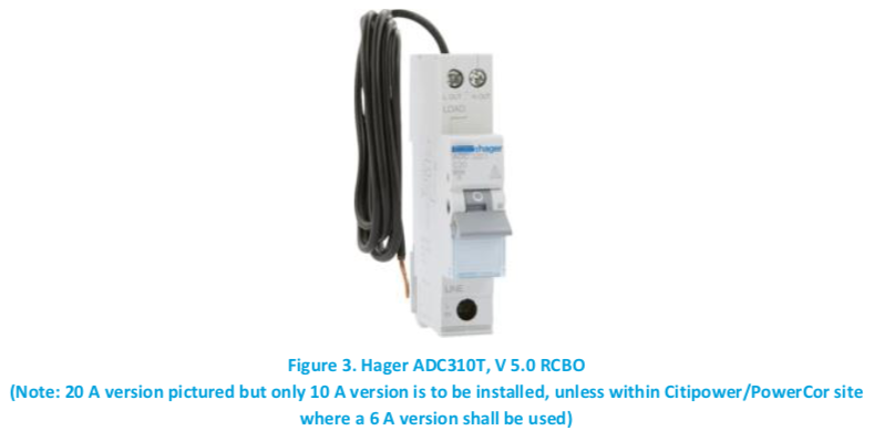
• Hager 10A RCBO, product code ADC310T, V5.0, dated March 2018 or later (excluding Victoria region)
• Hager 10A RCBO, product code ADC310T, V4.0, dated March 2018 or later (Only in Victoria, excluding
CitiPower/Powercor region)
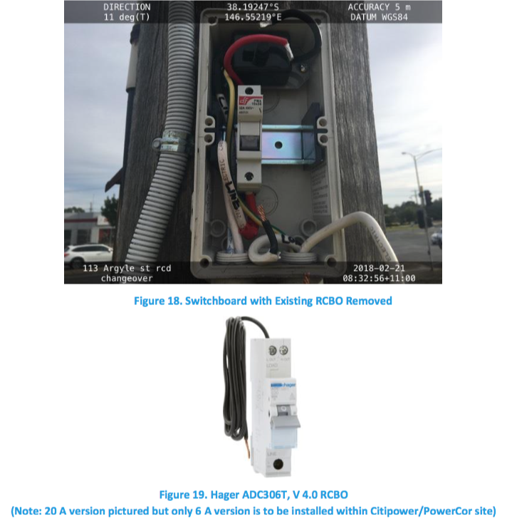
• Hager 6A RCBO, product code ADC306T V4.0, dated March 2018 or later (only within CitiPower/Powercor region)
• Active/neutral/earth cable (if required, refer to step A14 where new neutral cable may be required. Cable selection to match existing cable size and specification)
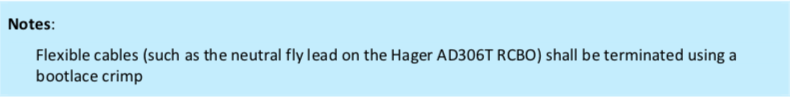
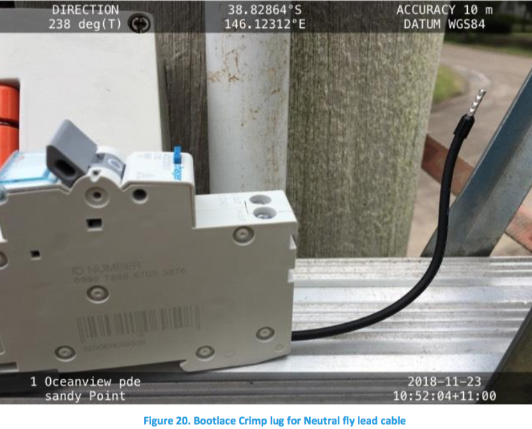
• Bootlace crimp lug -
-
PART 1 | PREPARE SITE
-
A1 - Contact FTTN NOC to “on site” as per BAU process.
-
A2 -Ensure Delivery Partner HSE requirements are applied, which shall include the use of relevant SWMS for the<br>activity undertaken.
-
A3 -Ensure safety prestart is conducted and appropriate safety controls are implemented in accordance with
relevant SWMS, such as: -
•Traffic and Pedestrian Management SWMS
-
• Electrical Work Activity SWMS
-
• Working at Heights (Working on poles)
-
• Working in Pits and Manholes
-
• Working on Ladders
-
• Working in EPR Zones
-
-
PART 2 | CONFIRM BACKUP SUPPLY & ISOLATE NORMAL SUPPLY
-
A4 - Check with FTTN NOC for remaining battery capacity. If capacity is sufficient to complete work without loss of service, proceed. If not, do not proceed.
-
A5 - .Does the Switchboard have water ingress?
-
a . Does the Switchboard require rehabilitation?
-
b . Does the Switchboard hold air pressure?
-
A6 - Isolate at the main switchboard fuse, or only if you are authorised to isolate at utility fuse and apply lockout tag as required.
-
-
A7 - Test and confirm that the outgoing circuit at main switchboard is isolated.
-
A8 - At the cabinet, test and confirm that the incoming supply is isolated.
-
A9 - Perform RCA (Root cause analysis) for RCBO tripping.
- WEAR & TEAR
- BAD CONNECTION-TERMINATION-LOOSE CONNECTION
- CABLE BREAK-AC MAINS
- WATER INGRESS
- EARTHING ISSUE
- DAMAGED CAUSE BY THIRD PARTY
- FAULT IN THIRD PARTY NETWORK I.E. UTILITY
- PLANNED OUTAGE IN THIRD PARTY NETWORK I.E. UTILITY
- PLANNED OUTAGE IN NBN NETWORK
- HARDWARE DEVICE FAILURE
- SOFTWARE-CONFIGURATION ISSUE
- THEFT-VANDALISM-SABOTAGE
- DESIGN ISSUE
- BUILD DEFECT
- CABINET KNOCKED OVER
- POLE KNOCKED OVER
- LOW HANGING CABLE
- COLLAPSED PIT
- HUMAN ERROR
- DAMAGE DUE TO PEST-VERMIN I.E. ANTS
- DAMAGE DUE TO ENVIRONMENTAL CONDITIONS I.E. STORM
- NATURAL DISASTER
- OVER CURRENT
-
PART 3 | INSTALL SI RCBO IN SWITCHBOARD
-
A10 - Disconnect active/neutral cable from existing RCBO.
-
A11 - Remove existing RCBO.
-
-
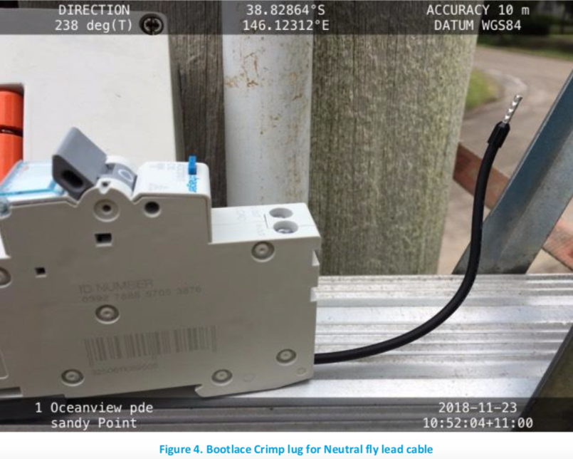
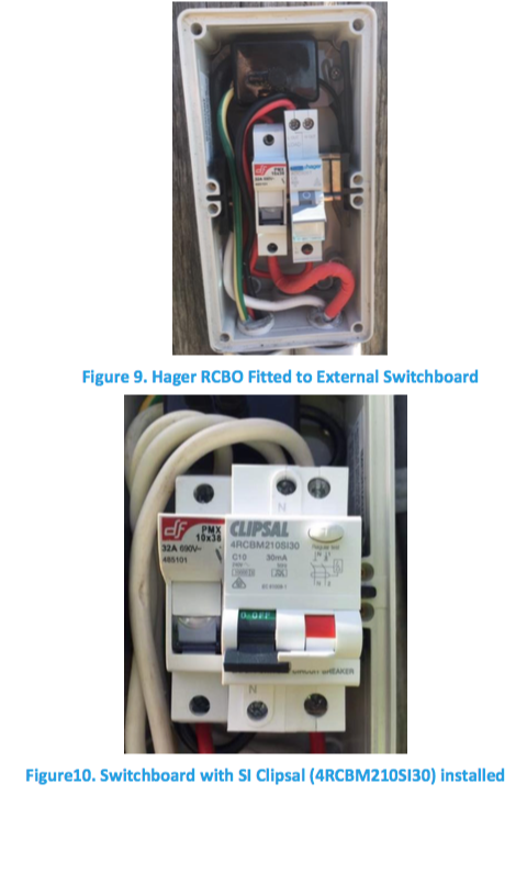
A12 - Install Hager RCBO. If working in Victoria, check to confirm the individual unit is approved (for details,<br>refer to Appendix A). If working in the CitiPower or Powercor distribution network area, use the 6A version.
-
-
A13 - Connect RCBO Line Neutral fly lead cable to switchboard neutral bar with bootlace crimp lug.
-
-
A14 - Ensure that RCBO is installed in the correct upright orientation on the DIN Rail and checks are made to ensure that gaining extra length does not disturb sealant or the overall integrity of the cabling in any way. Otherwise replace the cable.
-
A15 - If any work is conducted on an underground switchboard, to prevent water ingress the switchboard must be pressure tested by a competent and trained person, and necessary repairs completed to pass the testing, prior to the switchboard being reinstalled in the pit. (For details refer to NBN-CON-GDE-3479 nbn Underground Switchboard – Repair and Replacement Guide).
-
Photo of pressure gauge reading 2.5 PSI
-
A16 - Perform tests as required in AS/NZS 3000 and AS/NZS 3017
-
PART 4 | Energise, Test and Submit
-
A17 - Complete Certificate of Electrical Safety (or State-specific equivalent). [Refer sections 7 and 9]
-
A18 - Remove lock-out tag.
-
A19 - Re-connect supply (at fuse in main switchboard)
-
A20 - Complete any remaining tests, i.e. those that require supply to be available.
-
A21 - Ensure supply is working, cabinet is powered on and battery charging.
-
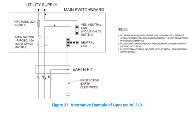
A22 - Mark up the existing AC Single Line Diagram (SLD) or replace with an updated laminated diagram, if<br>required (e.g. 2P RCBO to 1P RCBO).
-
A23 - Submit Certificate of Electrical Safety (or State-specific equivalent) to the relevant legislative body.
-
A24 - Prior to leaving the site, contact the FTTN NOC to advise job is completed.
-
A25 - Ensure supply is working and cabinet is powered on
-
A26 - Record peak start up current, less than 5.1 amps
-
27 - Record steady state current, between 2.1 & 2.5 amps
-
ARTEFACTS TO SUPPLY
-
-
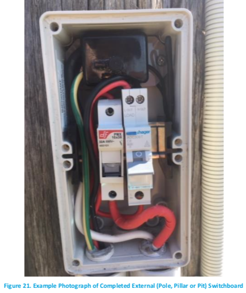
Photograph of completed external (pole, pillar or pit) switchboard.
-
-
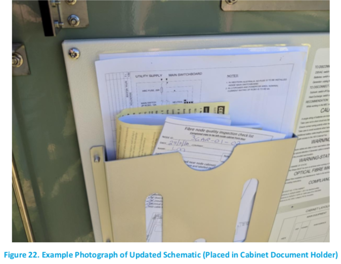
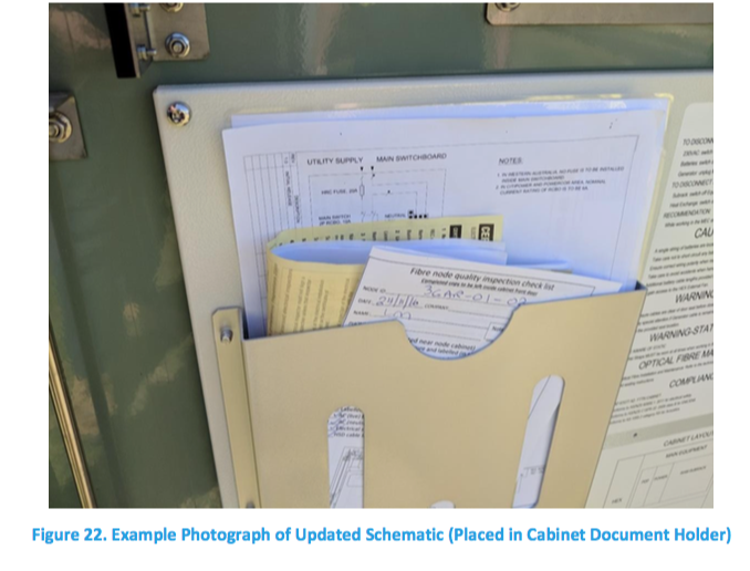
Photograph of updated schematic, which is to be placed in cabinet document holder
-
-
Photograph of AC SLD which is to be placed in cabinet document holder
-
-
Photograph or scan of Certificate of Electrical Safety (or State-specific equivalent)
-
-
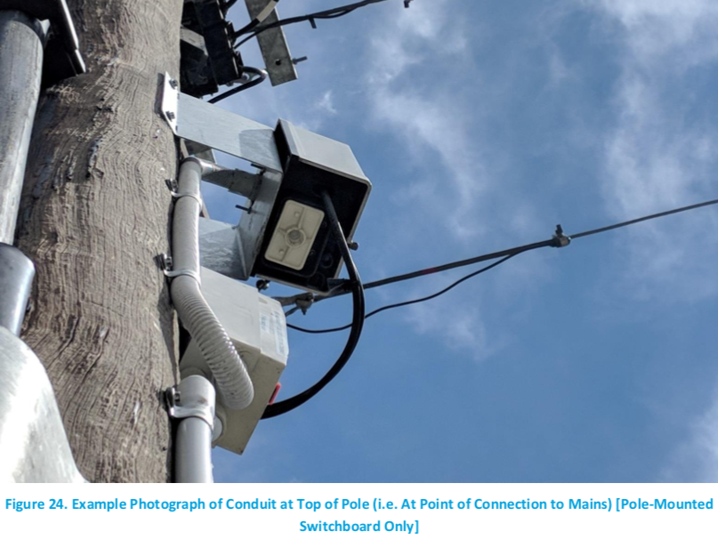
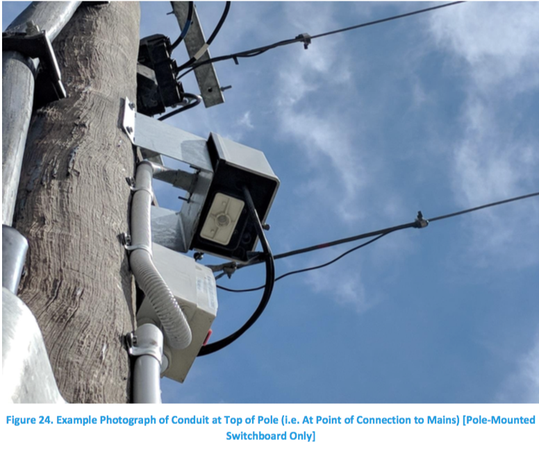
For pole-mounted switchboards: Photograph of conduit at top of pole (i.e. at point of connection to mains)
-
-
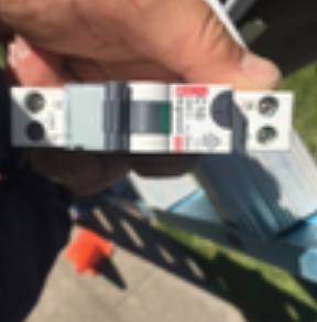
Photograph of removed RCBO clearly showing the model number (i.e. RCBO that was on site prior to works)
-
Provide noteworthy summary of site observations (such as cable damage, loose cable connections to switchboard and evidence of water ingress and vermin ingress)
-
Additional Site Observation Photo's.


ELECTRICAL LINES WORKER DOCUMENT
-
TOW -
-
INC -
-
Date of attendance
-
Site ID
-
Site Address
-
Start time leave base.
-
Supply photo to confirm location and date/time
-
Arrival Time at site Supply photo to confirm location and date/time
-
Call NOC to onsite job.
-
Time on site (hours) - Photo evidence required
-
Time leave site Supply photo to confirm location and date/time
-
Travelling to next job? Record time on next job.
-
Travelling home? Finish Address
-
Time arrive at base Supply photo to confirm location and date/time
-
Please advise in detail what actions were performed onsite (i.e.: what fault-finding results were registered / what actions were taken to rectify the issue) address:
-
SOR to be claimed Normal hours are between 6am – 6pm (Mon – Sat) - 09-01-01-09-AR
-
SOR to be claimed Any time outside normal hours including Public Holidays and if the call out is made on a Sunday - 09-01-01-09-OH
COMPLETION & SIGN-OFF
-
Add signature
• WMC Method of Procedure B– Nokia 384 cabinet - National
-
-
BILL OF MATERIALS
• Clipsal 4RCBM210SI30, 10A RCBO, supplied by nbn; ILM number 10026432 (excluding CitiPower/Powercor region) or Hager 6A RCBO, product code ADC306T V4.0, dated March 2018 or later (only within CitiPower/Powercor region)
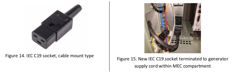
• IEC C19 socket, cable mount type.
• supply cord ‘test & tag’ inspection label for a testing regime of 5 yearly (burgundy colour code)
• Self-laminating vinyl label tape.
• Active/neutral/earth cable (if required, refer to step B13 where new neutral cable may be required. Cable selection to match existing cable size and specification)
• Bootlace crimp lug (Only for Hager ADC306T in Citipower/Powercor region) -
-
PART 1 | PREPARE SITE
-
B1 - Contact FTTN NOC to advise work is being undertaken at site.
-
B2 - Ensure Delivery Partner HSE requirements are applied, which shall include the use of relevant SWMS for the<br>activity undertaken.
-
B3 - Ensure safety prestart is conducted and appropriate safety controls are implemented in accordance with
Notes:
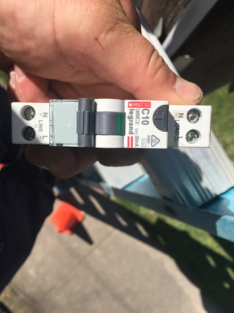
• This MoP is only relevant for the use of Clipsal SI 4RCBM210SI30 and Hager ADC306T.
• For Western Australia sites, no fuse is to be installed inside the main switchboard.
Notes:
Flexible cables (such as the neutral fly lead on the Hager AD306T RCBO) shall be terminated using a bootlace crimp
relevant SWMS, such as: -
• Traffic and Pedestrian Management SWMS
-
• Electrical Work Activity SWMS
-
• Barriers
-
• Low voltage rescue kit is available
-
-
Working in EPR Zones
-
-
PART 2 | CONFIRM BACKUP SUPPLY & ISOLATE NORMAL SUPPLY
-
B4 - Check with FTTN NOC for remaining battery capacity. If capacity is sufficient to complete work without loss of service, proceed. If not, do not proceed.
-
B5 - .Does the Switchboard have water ingress?
-
a . Does the Switchboard require rehabilitation?
-
b . Does the Switchboard hold air pressure?
-
B6 - Test and confirm outgoing subcircuit at main switchboard is isolated.
-
-
B7 - Test and confirm that the outgoing circuit at main switchboard is isolated.
-
B8 - At the cabinet, test and confirm that the incoming supply is isolated.
-
B9 - Disconnect active cable between SPD and the busbar at the MCB's
-
PART 3 | Replace RCBO
-
B10 - Install SI RCBO on DIN-rail between SPD(s) and 2x rectifier MCB's
-
B11 - Install 6 mm2 active cable between SPD and SI RCBO
-
a. If in CitiPower or Powercor distribution area, use Hager ADC306T (6 A).
b. If in other distribution areas, use Clipsal 4RCBM210SI30 (10 A). -
-
-
B12 - Connect RCBO Line Neutral fly lead cable to switchboard neutral bar with bootlace crimp lug (for Hager<br>only).
-
-
B13 - Ensure that RCBO is installed in the correct upright orientation on the DIN Rail and checks are made to ensure that gaining extra length does not disturb sealant or the overall integrity of the cabling in any way. Otherwise replacement of the neutral cable may be required following assessment.
-
B14 - Remove 3rd rectifier subcircuit neutral conductor (unused socket)
-
B15 - Perform tests as required in AS/NZS 3000 and AS/NZS 3017, with particular attention to the verification of the location of the main protective earth electrode and sub-main earth conductor are suitable to meet fault- loop impedance.
-
-
PART 4 | Internal Cabinet Work -Plug & Cord Conversion”
-
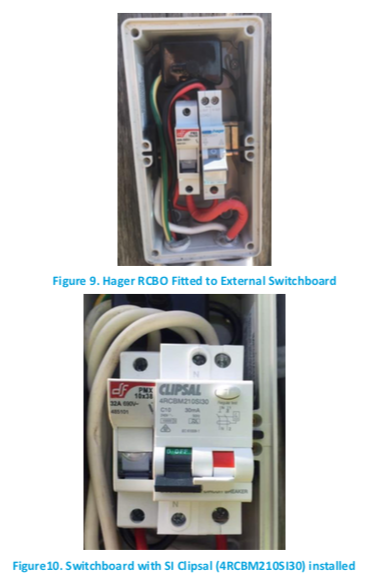
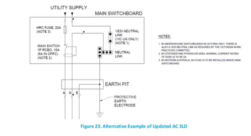
B16 - [Victoria only] Section 5 of each Victorian nbn Power Manual directs an unswitched normal supply neutral at the changeover switch in Nokia 384-line FTTN cabinets. However, the normal supply neutral conductor shall remain switched at the changeover switch as shown in Figure 16. Approporiate investigation and changes should be performed to achieve this configuration.
-
B17 -The N-E link (earth wire) between changeover switch and cabinet PE bar shall be removed.
-
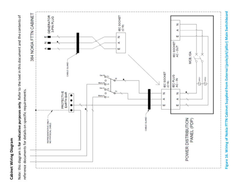
B18 - Disconnect generator supply cord (the cord with a 3 pin plug stored in the yellow holder) active &<br>neutral from changeover switch and earth from PE bar, and feed cord through gland into MEC compartment.
-
-
B19 - To the end of the cord, terminate an IEC C19 cable mount socket. Note: ensure the newly terminated cord is tested & tagged based on the 5 yearly testing regime.
-
B20 - Reconnect outgoing neutral cable directly to the neutral bar. If cable length is too short, utilize a cable connector (Clipsal part number 563L2)
-
B21 - Update labelling to cover of changeover switch to state “NORMAL SUPPLY ISOLATION SWITCH”.
-
-
-
PART 5 | ENERGIZE, TEST AND SUBMIT
-
B22 - Complete Certificate of Electrical Safety
-
B23 - Remove lock-out tag.
-
B24 - Re-connect supply (at fuse in main switchboard)
-
B25 - Complete any remaining tests, i.e. those that require supply to be available.
-
B26 - Ensure supply is working, cabinet is powered on and battery charging.
-
B27 - Mark up the existing AC Single Line Diagram (SLD) or replace with an updated laminated diagram, if<br>required (e.g. 2P RCBO to 1P RCBO, 1P RCBO to 2P RCBO).
-
B28 - Print out schematic diagram for Internal wiring fig [16] and stored within the cabinet, and a copy needs to<br>be submitted to nbn along with other Artefacts refer [11]
-
B29 - Submit Certificate of Electrical Safety (or State-specific equivalent) to the relevant legislative body.
-
B30 - Prior to leaving the site, contact the FTTN NOC to advise job is completed.
-
B31 - Submit the below listed artefacts (certificate, photographs and data collection checklist) to nbn FTTN<br>NOC. Refer to Section 11 Artefacts to be Supplied to nbn
-
ARTEFACTS TO SUPPLY
-
-
Photograph of completed external (pole, pillar or pit) switchboard.
-
-
Photograph of updated schematic, which is to be placed in cabinet document holder
-
-
Photograph of AC SLD which is to be placed in cabinet document holder
-
-
Photograph or scan of Certificate of Electrical Safety (or State-specific equivalent)
-
-
For pole-mounted switchboards: Photograph of conduit at top of pole (i.e. at point of connection to mains)
-
-
Photograph of removed RCBO clearly showing the model number (i.e. RCBO that was on site prior to works)
-
Provide noteworthy summary of site observations (such as cable damage, loose cable connections to switchboard and evidence of water ingress and vermin ingress)
-
Additional Site Observation Photo's.


ELECTRICAL LINES WORKERS DOCUMENT
-
TOW -
-
INC -
-
Date of attendance
-
Site ID
-
Site Address
-
Start time leave base.
-
Supply photo to confirm location and date/time
-
Arrival Time at site Supply photo to confirm location and date/time
-
Call NOC to onsite job.
-
Time on site (hours) - Photo evidence required
-
Time leave site Supply photo to confirm location and date/time
-
Travelling to next job? Record time on next job.
-
Travelling home? Finish Address
-
Time arrive at base Supply photo to confirm location and date/time
-
Please advise in detail what actions were performed onsite (i.e.: what fault-finding results were registered / what actions were taken to rectify the issue) address:
-
SOR to be claimed Normal hours are between 6am – 6pm (Mon – Sat) - 09-01-01-09-AR
-
SOR to be claimed Any time outside normal hours including Public Holidays and if the call out is made on a Sunday - 09-01-01-09-OH
COMPLETION & SIGN-OFF
-
Add signature
• WMC Method of Procedure C– Nokia 192/CSD cabinet - National
-
-
Bill of Materials
• Clipsal 4RCBM210SI30, 10A RCBO, supplied by nbn; ILM number 10026432 (excluding CitiPower/Powercor region) or Hager 6A RCBO, product code ADC306T V4.0, dated March 2018 or later (only within CitiPower/Powercor region)
• Active/neutral/earth cable (if required, refer to step C13 where new neutral cable may be required. Cable selection to match existing cable size and specification)
• Bootlace crimp lug (Only for Hager ADC306T in Citipower/Powercor region)
• Note: flexible cables (such as the neutral fly lead on the Hager ADC306T RCBO) shall be terminated using a
bootlace crimp. -
PART 1 | PREPARE SITE
-
C1 - Contact FTTN NOC to “on site” as per BAU process.
-
C2 - Ensure Delivery Partner HSE requirements are applied, which shall include the use of relevant SWMS for the<br>activity undertaken.
-
C3. Ensure safety prestart is conducted and appropriate safety controls are implemented in accordance with<br>relevant SWMS, such as:
-
C3 - Ensure safety prestart is conducted and appropriate controls are implemented, such as:
-
• Traffic and Pedestrian Management SWMS
-
• Electrical Work Activity SWMS
-
• Working at Heights (Working on poles)
-
• Working in Pits and Manholes
-
• Working on Ladders
-
• Working in EPR Zones
-
-
PART 2 | CONFIRM BACKUP SUPPLY & ISOLATE NORMAL SUPPLY
-
C4 - Check with FTTN NOC for remaining battery capacity. If capacity is sufficient to complete work without loss of service, proceed. If not, do not proceed.
-
C5 - .Does the Switchboard have water ingress?
-
a . Does the Switchboard require rehabilitation?
-
b . Does the Switchboard hold air pressure?
-
C6 - Isolate at the main switchboard fuse, or only if you are authorised isolate at utility fuse and apply lockout tag as required.
-
-
C7 - Test and confirm that the outgoing circuit at main switchboard is isolated.
-
C8 - At the cabinet, test and confirm that the incoming supply is isolated.
-
C9 - Perform RCA (Root Cause Analysis) for RCBO tripping.
-
PART 3 | Replace RCBO.
-
C10 - Disconnect active/neutral cable from existing RCBO.
-
C11 - Remove and discard the pre-installed RCBO in external switchboard and replace as follows:
-
a. If in CitiPower or Powercor distribution area, use Hager ADC306T (6 A).
-
b. If in other distribution areas, use Clipsal 4RCBM210SI30 (10 A).
-
-
C12 - Connect RCBO Line Neutral fly lead cable to switchboard neutral bar with bootlace crimp lug (Hager only).
-
-
C13 - Ensure that RCBO is installed in the correct upright orientation on the DIN Rail and checks are made to ensure that gaining extra length does not disturb sealant or the overall integrity of the cabling in any way. Otherwise replace the cable. If any work is conducted on an underground switchboard, to prevent water ingress the switchboard must be pressure tested by a competent and trained person, and necessary repairs completed to pass the testing, prior to the switchboard being reinstalled in the pit. (For details refer to NBN- CON-GDE-3479 nbn Underground Switchboard – Repair and Replacement Guide).
-
C14 - Perform tests as required in AS/NZS 3000 and AS/NZS 3017
-
Part 4 Energise, Test and Submit
-
C15 - Complete Certificate of Electrical Safety (or State-specific equivalent). Refer sections 7and 9.
-
C16 - Remove lock-out tag.
-
C17 - Re-connect supply (at fuse in main switchboard)
-
C18 - Complete any remaining tests, i.e. those that require supply to be available.
-
<br>C19 - Ensure supply is working, cabinet is powered on and battery charging.
-
C20 - Mark up the existing AC Single Line Diagram (SLD) or replace with an updated laminated diagram, if<br>required (e.g. 2P RCBO to 1P RCBO, 1P RCBO to 2P RCBO).
-
C21 - Submit Certificate of Electrical Safety (or State-specific equivalent) to the relevant legislative body.
-
C22 - Prior to leaving the site, contact the FTTN NOC to advise job is completed.
-
C23 - Submit the below listed artefacts (certificate photographs and, data collection checklist) to nbn FTTN NOC. Refer to Section 11 Artefacts to be Supplied to nbn
-
ARTEFACTS TO SUPPLY
-
-
Photograph of completed external (pole, pillar or pit) switchboard.
-
-
Photograph of updated schematic (to be placed in cabinet document holder).
-
-
Photograph of AC SLD which is to be placed in cabinet document holder
-
-
Photograph or scan of Certificate of Electrical Safety (or State-specific equivalent)
-
-
For pole-mounted switchboards: Photograph of conduit at top of pole (i.e. at point of connection to mains)
-
-
Photograph of removed RCBO clearly showing the model number (i.e. RCBO that was on site prior to works)
-
Provide noteworthy summary of site observations (such as cable damage, loose cable connections to switchboard and evidence of water ingress and vermin ingress)
-
Additional Site Observation Photo's.

ELECTRICAL LINES WORKERS DOCUMENT
-
TOW -
-
INC -
-
Date of attendance
-
Site ID
-
Site Address
-
Start time leave base.
-
Supply photo to confirm location and date/time
-
Arrival Time at site Supply photo to confirm location and date/time
-
Call NOC to onsite job.
-
Time on site (hours) - Photo evidence required
-
Time leave site Supply photo to confirm location and date/time
-
Travelling to next job? Record time on next job.
-
Travelling home? Finish Address
-
Time arrive at base Supply photo to confirm location and date/time
-
Please advise in detail what actions were performed onsite (i.e.: what fault-finding results were registered / what actions were taken to rectify the issue) address:
-
SOR to be claimed Normal hours are between 6am – 6pm (Mon – Sat) - 09-01-01-09-AR
-
SOR to be claimed Any time outside normal hours including Public Holidays and if the call out is made on a Sunday - 09-01-01-09-OH
COMPLETION & SIGN-OFF
-
Add signature

