")


TASK EXECUTION │ PROCEDURE / PROCESS
-
The purpose of this SWI is to provide sufficient procedure and information for performing planned online electrical inspections on the Underground drill bays. This procedure applies to the Underground drill bays. Approximately 1 Hour. File Document name: 10000413774
Please see attached SWI for Underground Drill Bay Electrical Inspection -
Please read above attached the SWI for Underground, Drill Bay Electrical Inspection
Conducted
-
Conducted on
-
Inspected by
-
Work Order number
-
Location
-
Qualification: Electricians - Trained, competent and authorized for the task.
HEALTH, SAFETY & ENVIRONMENTAL CONSIDERATIONS
Contact with Electricity
-
Contact with Electricity
Please follow below CRM controls
• Electrical Isolation and Lockout
• Verification of Zero Energy

Slip, trip, and falls
-
• A high standard of housekeeping shall be always maintained to prevent trip hazards.
• Be wary while walking around the pumps, motors, and other live equipment as the area might be slippery. -
Use appropriate PPE
Visibility and lightings
-
Use a headlamp or flashlight when working at the pump station
Force
-
• Regular rest
• Use appropriate tools.
• Avoid using brute force.
• Work in a team and ask for help from others -
Maintain good communication

Work instructions
1. PRE-START PREPARATIONS & ISOLATION (MUST FOLLOW C1 ISOLATION PROCESS)
-
1.1 Identify and control the hazards using the TRACK
-
1.2 Prepare material and tools:<br>Ensure that you have the necessary equipment/tools available at the site:<br>- Required Materials<br>- Required PPE<br>- Maintain good housekeeping<br>Proper Inspection of all tools and equipment
-
1.3 Inform the maintenance supervisor or team lead of the scope of work and that work about to start.
2. BAY VENTILATION AND LIGHTS CHECK
-
2.1 Begin your search on the right side of the drill bay, as indicated to locate the Light/Fan switch
-
2.2 Step Instruction
-
2.2 Functional Test: <br>Activate the switch to turn on the ventilation fan.<br>Observe the airflow produced by the fan. <br><br>It should be strong and consistent. Light/Fan Label: Verify that the label on the switch or control panel is clear, easy to read.
-
2.3 Step Instruction
-
2.3 Ensure that the "Establish Ventilation Before Entry" sign is clearly visible, legible, and in good condition.
-
2.4 Step Instruction
-
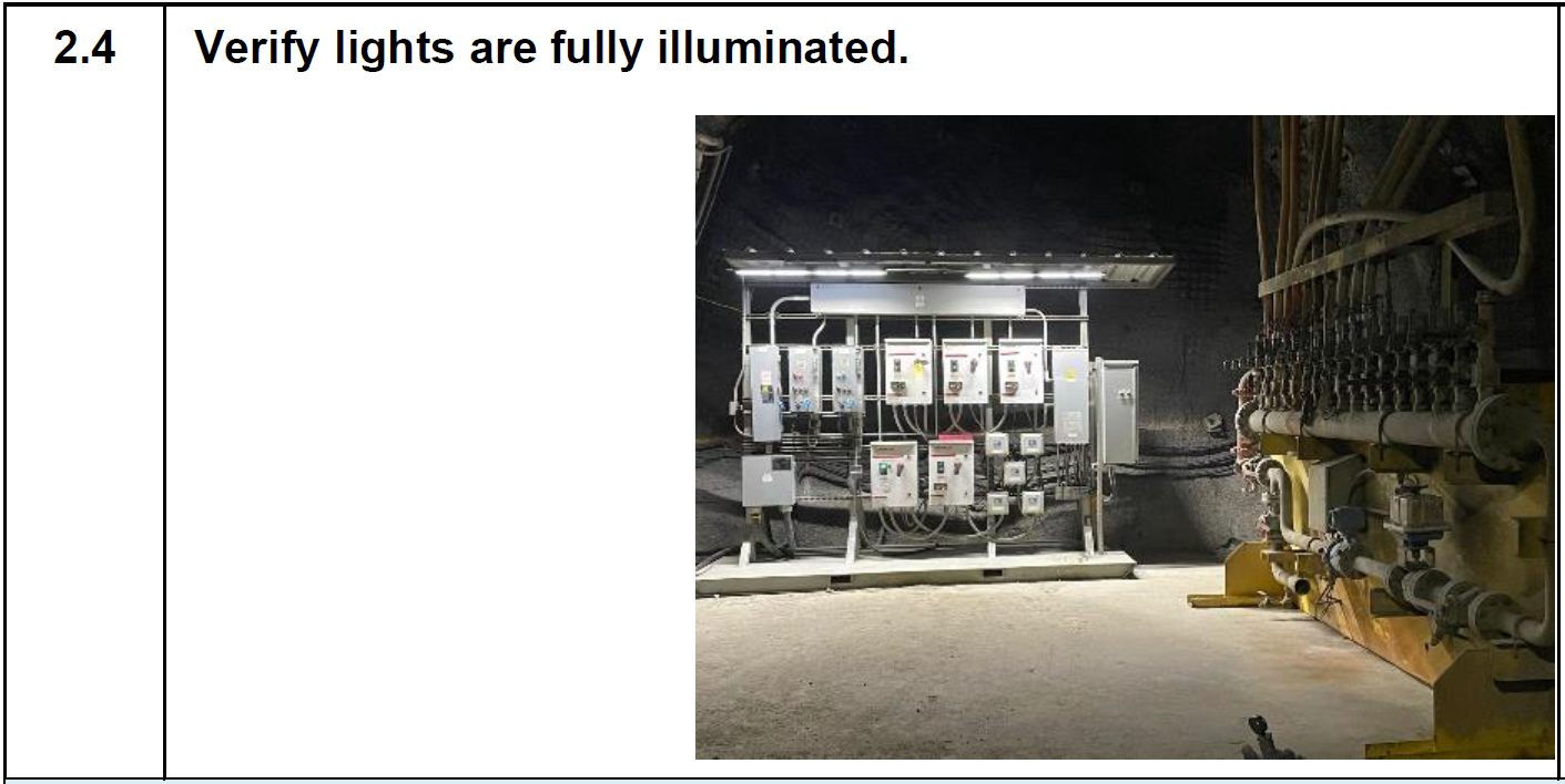
2.4 Verify lights are fully illuminated.


3. BAY GROUND SUPPORT INSPECTION
-
3.1 Stability: Accepted Conditions:<br>• No visible signs of loose rocks, cracks, or bulges.<br>• Rock formation appears stable and solid.<br>Unaccepted Conditions:<br>• Loose rocks, boulders, or debris are present.<br>• Visible cracks or fissures in the rock.<br>• Bulging or swelling of the rock formation.
-
3.2 Water:<br>Make sure that:<br>• No standing water or puddles.<br>• No visible leaks or excessive moisture.
4. BAY AREA INSPECTION
-
4.1 Is general housekeeping in the workplace in good condition?
-
4.2 Are entrance, walkways, travel ways, and floor free from obstruction and slip and trip hazard?
-
4.3 Verify required area clearance. <br>Safety Signage:<br>• Confirm all required safety signs are present, legible, and undamaged.<br> - Electrical hazard signs <br> - Highest Voltage Potential sign <br> - Fire extinguisher sign
5. FIRE EXTINGUSHER INSPECTION
-
5.1 Step Instruction
-
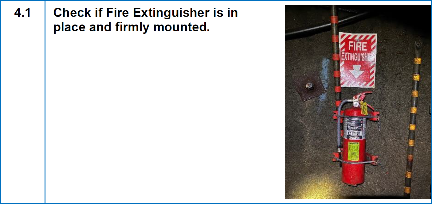
5.1 Check if Fire Extinguisher is in place and firmly mounted.
-
5.2 Step Instruction
-
5.2 Check Pressure needle is in green region.
-
5.3 Step Instruction
-
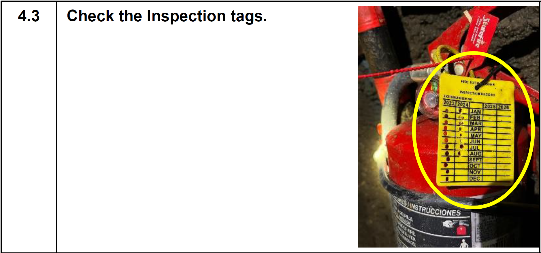
5.3 Check the Inspection tags.
-
Fire Extinguisher Tag Inspected Date

6. JUNCTION BOX
-
6.1 Step Instruction
-
6.1 Look for any physical damage to the enclosures of all panels, including cracks, dents, or rust for the panel’s doors<br>Check for any damage (chewed wires, droppings) feeding the Panel.<br>Check cables labeling.<br>Check the BLUE lock if its there and locked.
-
6.1.1 - 6.1.6 Steps Instruction
-
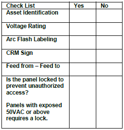
6.1.1 Asset Identification
-
6.1.2 Voltage Rating
-
6.1.3 Arc Flash Labeling
-
6.1.4 CRM Sign
-
6.1.5 Feed from – Feed to
-
6.1.6 Is the panel locked to prevent unauthorized access?
-
6.2 Check for signs of water leaks or moisture buildup outside the panels.
-
6.3 Look for any signs of excessive corrosion on the exterior of the panels.


7. PUMP Control Panel
-
7.1 Step Instruction
-
7.1 Look for any physical damage to the enclosures of all panels, including cracks, dents, or rust for the panel’s doors<br>Check for any damage (chewed wires, droppings) feeding the Panel.<br>Check cables labeling.<br>Check the BLUE lock if its there and locked.
-
7.1.1 - 7.1.6 Steps Instruction
-
7.1.1 Asset Identification
-
7.1.2 Voltage Rating
-
7.1.3 Arc Flash Labeling
-
7.1.4 CRM Sign
-
7.1.5 Feed from – Feed to
-
7.1.6 Is the panel locked to prevent unauthorized access?
-
7.2 Check for signs of water leaks or moisture buildup outside the panels.
-
7.3 Look for any signs of excessive corrosion on the exterior of the panels.


8. FAN Control Panel
-
8.1 Step Instruction
-
8.1 Look for any physical damage to the enclosures of all panels, including cracks, dents, or rust for the panel’s doors<br>Check for any damage (chewed wires, droppings) feeding the Panel.<br>Check cables labeling.<br>Check the BLUE lock if its there and locked.
-
8.1.1 - 8.1.6 Steps Instruction
-
8.1.1 Asset Identification
-
8.1.2 Voltage Rating
-
8.1.3 Arc Flash Labeling
-
8.1.4 CRM Sign
-
8.1.5 Feed from – Feed to
-
8.1.6 Is the panel locked to prevent unauthorized access?
-
8.2 Check for signs of water leaks or moisture buildup outside the panels.
-
8.3 Look for any signs of excessive corrosion on the exterior of the panels.


9. WELL PUMP CONTROL PANELS
-
9.1 Step Instruction
-
9.1 Look for any physical damage to the enclosures of all panels, including cracks, dents, or rust.<br>for any damage (chewed wires, droppings) feeding the Panel.<br>Check that all labeling on panel indicators and switches are in good condition and readable.
-
9.1.1 - 9.1.6 Steps Instruction
-
9.1.1 Asset Identification
-
9.1.2 Voltage Rating
-
9.1.3 Arc Flash Labeling
-
9.1.4 CRM Sign
-
9.1.5 Feed from – Feed to
-
9.1.6 Is the panel locked to prevent unauthorized access?
-
9.2 Check for signs of water leaks or moisture buildup outside the panels.
-
9.3 Look for any signs of excessive corrosion on the exterior of the panels.

10. GEM SENSOR TERM BOX
-
10.1 Step Instruction
-
10.1 Look for any signs of corrosion on visible metal components.<br>Visually inspect the blue lock for any signs of cracks, breaks in the lock housing, bent, rusty, Corrosion or damage around the lock.
-
10.1.1 - 10.1.5 Steps Instruction
-
10.1.1 Asset Identification
-
10.1.2 Voltage Rating
-
10.1.3 Arc Flash Labeling
-
10.1.4 CRM Sign
-
10.1.5 Feed from – Feed to
-
10.2 Check for signs of water leaks or moisture buildup outside the panels.
-
10.3 Look for any signs of excessive corrosion on the exterior of the panels.


11. REMOTE I/O PANEL
-
11.1 Step Instruction
-
11.1 Look for any physical damage to the enclosures of all panels, including cracks, dents, or rust.<br>for any damage (chewed wires, droppings) feeding the Panel.<br>Check that all labeling on panel indicators and switches are in good condition and readable.
-
11.1.1 - 11.1.6 Steps Instruction
-
11.1.1 Asset Identification
-
11.1.2 Voltage Rating
-
11.1.3 Arc Flash Labeling
-
11.1.4 CRM Sign
-
11.1.5 Feed from – Feed to
-
11.1.6 Is the panel locked to prevent unauthorized access?
-
11.2 Check for signs of water leaks or moisture buildup outside the panels.
-
11.3 Look for any signs of excessive corrosion on the exterior of the panels.


12. TASK COMPLETION
-
12.1 Clean work area of old or used parts.
-
12.2 Return all unused parts to the warehouse.
-
12.3 Clean and return all equipment and supplies to their proper location.
-
12.4 Clean any used specialty tools and return them to their specified location.
-
12.5 Is the task fully completed? Notify the underground shift supervisor that the Electrical monthly online inspections are complete, and it is back in operation.
-
12.6 Report any defects to the supervisors and the planning team.<br>Any repair done must also be recorded.
-
ADDITIONAL COMMENTS:
-
Signature
")
")
")
")
")
")
")
")
")
")