Title Page
-
Document nr
-
Description
-
Site conducted
-
Prepared by
-
Date
-
Site Location
-
Client Name
-
Other Comments
A. Client Handover
-
Grid Lines and Datum, Safe area of work, Skip ...
B. Drawings
-
Design, Details Drawings, Data Sheet & installation guide checked
QAC-Inspection Checklist
- 1. Mineral Wool EWI
-
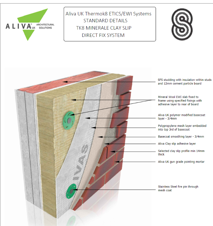
240 mm Mineral Wool EWI slab fixed to frame using specified fixings with adhesive layer to rear of board.Adefix/Klebocem UK Grosso Basecoat Adhesive render to rear of boards. IVAS EWI - A1 Non-Combustible Mineral Wool Insulation.2. For the rear of the insulation boards, the adhesive basecoat should be applied using a 10mm serrated edge trowel to follow the shortest direction.<br>
-
Insulation, fix with Textured outer face of the slab, close edges of the slabs at all vertical and horizontal joints, Stagger the horizontal joints min 100mm, Fixings min 1 no metal and 2 no polypropylene per board, @ max 500 cents, minimum head diameter of 70mm. check project spec
-
Render Band :2No. layers of Y-Wall Boards, Mineral Wool EWI slab fixed to substrate ( @ 400mm c/c ),Compressible insulation backing rod and external mastic. R10 Stop Bead.
-
Cuts to openings to be formed with a L shape cut. Min cuts 200mm.
-
Boards to corners.Lapped toothed detail for all boards to corners. When installing the insulation boards to corners ensure that boards are staggered and lapping to form a toothed detail, as above. No cuts less than 200mm thick. Allow fixings to corners at 300mm centres and no less than 200mm from the edges. Ensure L shape cuts to corners of openings as detail provided
-
System brick slip starter track to suit insulation depth set at DPC layer -generally 150mm above Ground Level
-
High Density moisture resistant insulation for use below ground with basecoat and bituminous paint finish
2. Basecoat
-
Aliva UK polymer modified basecoat layer - 3/4mm . Adefix/Kleboce, UK Grosso Polymer modified cement base render First mesh coat, layer 4 mm<br>
-
Polymer modified cement base render Second 2nd smoothing coat, layer 4 mm<br>
-
Polypropylene mesh layer embedded into top 3rd of basecoat,Reinforcement Mesh, Armatex A1 mesh
-
All mesh to lap by min.100mm and lapped with mesh wings to corner beads.
-
Allow for stress patches of 250x250mm cuts of mesh
-
Fixings Stainless Steel fire pin through mesh coat
-
Basecoat smoothing layer - 3/4mm
3. Windows and Doors Reveal & Head Details
-
APU Frameseal bead fixed to window frame with mesh wing over lapping corner bead mesh
-
External grade mastic
Hold Point 1
-
Hold Point Inspection putting a hold on construction activities until the inspection above is passed. Is a mandatory verification point beyond which a work process cannot proceed without authorisation by the contract administrator. Hold points are usually assigned to those critical aspects of the work that cannot be inspected or corrected at a later stage because they will no longer be accessible.
4. Render Topcoat Band
-
Rivetone Plus TRV G15 (1.5mm grain coloured texture) Render Band as per architects setting out
5. Aliva Clay Brick Slips
-
Aliva Clay slip adhesive layer. Collanti Gluflex Ultra Cementitious Clay Slip Adhesive, layer 5mm applied.2 The adhesive basecoat should be applied using a 10mm serrated edge trowel to follow the shortest direction.<br>
-
Selected clay slip profile 22.5mm thick, Strat Setting Out from Corner & Windows Head & Jamb & Between. Ensure perp joints align.When installing the clay slips, ensure the rear of the slips are 'buttered' with a serrated edge trowel as indicated over, and the clay slip embedded into the adhesive by a minimum of 5mm
-
Clay slip pre-formed corner pistol profile
-
Aliva UK gun grade pointing mortar
6. Movement Joint
-
A# Horizontal Movement Joint as per location/datum/details. Fire Pin. Back to back stop beads (R6).Compressible insulation backing rod and external mastic.<br>
-
B# Vertical Movement Joints as per location/datum/details
7. Specification
-
Clay Slip ;<br>Manufacturer: Vandersanden<br>Product: Woodland Mixture (52)<br>Mortar: Parex Standard Mortar White (EA108)<br>Bond: Stretcher<br>Pointing: Bucket Handle<br>Airbrick: Hepworth Terracotta Buff<br>Movement Joint: Mastic to match mort<br>
8. Comments or Additional Details
-
Hold Point 2 Flashings , Copings and Fixings
- 9. Windows Flashings & Cills
-
A# Cills & Flashings & Aluminium Cleat Support B# Insect mesh @ Bottom & Top of the Cladding - check project spec C# Aluminium PPC: Jamb Closer, PPC Ventilation, Corner, Drip flashing – project spec. Window cill fixed to frame by others to have upturned wings to sides to allow system to be installed over to provide a full seal.
-
35mm Overhang min Cill, Flashings
10. Copings Installation
-
EPDM Membrane installation
-
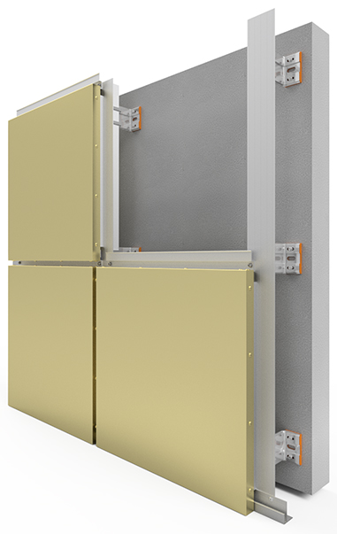
Aluminium Support BRACKETS Installation ,Line and level the bracket , fixings to spec ,INSTALLATION INSTRUCTIONS
-
Mineral Wool Insulation Installation
11. Fixings
-
Fixings Specification used
12. Other Details or Comments ,Instruction ,Delays ,RFI`s...
-
Hold Point 3: Handover
- 13. Handover Inspection
-
Site Manager Handover Inspection
-
Further to our site inspections and quality control inspections, we can confirm that the installation at the above-noted project is in accordance with the project and the manufacturer's installation guidance. Hand Over -Cladding free from damage-Facades to be viewed as per the BBA, in daylight from a distance of not less than 10m. Some variation in the colour and texture of external walls is inevitable and in certain cases is a feature. A façade for instance should be inspected for scratches or minor imperfections from a distance of min 5m, if a scratch cannot be seen from that distance then it is not a defect except if a scratch has gone through the full depth of the coating exposing the raw metal below. Inspection conditions Guidelines for Glass Quality.1.1 For general applications quality inspection is routinely carried out by the visual observation that is looking through the glass in normal incidence (i.e. at 90 degrees to the glass surface). In line with the Glass and Glazing Federation (GGF) and CWCT Guidelines, the glass shall be viewed from a distance of not less than 3 metres away. The use of strong lamps and/or magnifying devices is not allowed. It is not permissible to find defects at close range and then mark them so as to be visible from the given viewing distance.
