


Title Page
-
Name of trainee completing induction
-
Induction Date / Time
-
Induction Conducted by
-
Venue
System Overview:
-
COUNTERWEIGHT SETS The Fly System is comprised of Counterweight sets that are designed to enable vertical movement and storage of items of scenery, lighting or other stage equipment. Each set consists of an 18m scenery pipe battens, 18m long lighting bars, or 11.6m panorama bars (*which run upstage downstage) . Suspended from 6 wire ropes running over pulleys and back to a counterweight cradle which is operated by a hand hauled manila rope. Each cradle is constrained to run in the guide by nylon rollers. Inadvertent movement of the counterweight set is prevented by a rope lock which is operated at stage level and which can be padlocked against unauthorized release. The counterweight cradle loading is variable to correspond with the weight of scenery etc. attached to the batten. This is achieved by adding or subtracting cast iron weights.
-
WALL FRAME AND GUIDE ASSEMBLY The wall frame is constructed from horizontal steel angle members to guide the counterweight cradles. The wall frame includes a wooden buffer to limit travel of the cradle in extreme upper and lower positions. The wall frame should be inspected *annually for alignment and bolt torsion are maintained.
-
BATTENS Battens for general purpose sets are 40NB medium steel pipe in continuous lengths of 18m to enable use of standard clamps for fitting other devices. Panorama battens are 11.6m long. The approximate vertical travel of battens (or drift) measured from 300 mm above stage level is *17m.
-
LINES AND LINE ATTACHMENT Battens are attached to the lines by bolted clamps and lengths of galvanized trim chains to allow height adjustment. Each batten is flown by 6 suspension lines of 6mm 7 x 19 fibre core galvanised rope
-
COUNTERWEIGHT CRADLES (**draft note confirm WLL and batten balance with an empty batten) The counterweight cradle holds the iron weight blocks in two levels to balance the load of each set each cradle level can accommodate 20 standard blocks totalling a maximum of 40 blocks per cradle. The cradle travels up and down the wall frame and guide assembly by hauling the manila rope of each set through the lever handle rope lock. The cradle is designed with a weight lock device that should be secured at all times outside of weight loading operations. If the required counterweight quantity is reaching the top of the allowable space in the cradle the weight lock may not fit at which point one of the "self clamping" 6kg weights should be used in-place of the weight lock. NOTE: AN EMPTY COUNTERWEIGHT CRADLE EXACTLY BALANCES AN UNLOADED BATTEN.
-
WEIGHTS Iron weight blocks are designed to fit each cradle for secure stacking of balance load. *12kg full size blocks are to be used as primary balance weight, 7kg bloacks are used as secondary trim weight to find optimal balance.
-
ROPE LEVER LOCKS A lever operated rope lock is provided on each counterweight set. This has a cam arrangement to clamp the hauling line in the desired position. The lock has limited adjustment to compensate for rope wear. It is important to note that the lock is deliberately designed not to hold large out of balance loads. **the maximum clamping force of each lever Lock is 24kg**
-
ROPE FRICTION LOCKS Distinct from the Lever locks that are integrated into each counterweight set the rope friction locks are removable hardware to increase friction on the hauling lines to secure unbalanced weights as required. These friction devices should only be used by compotent and inducted operators. Before removing any friction locks the Fly Supervisor should be consulted and the line under load should be checked for balance before removing the lock. These friction locks can be doubled on a counterweight set to increase again the friction lock of a set whilst loading operations are underway or as required.
-
HAULING ROPE Each counterweight set consists of a hauling line / rope which is a large diamater manila braided rope. This rope is installed vertically to assist the controlled travel of each cradle and passes through the integrated rope lever lock of each set.
Terms - a non exhaustive list of terms used in the operation and servicing of a counterweight fly system.
-
Travel OUT - to haul the counterweight cradle towards stage thus lifting the corresponding batten OUT or UP towards the grid.
-
Travel IN - to haul the counterweight cradel towards the grid thus lowering the corresponding batten IN or DOWN towards the stage.
-
Prompt side - also known as stage left. The side of the stage that from the audience perspective is the right hand side of stage.
-
Off Prompt side - Also know as OP or stage right. The side of the stage that from the audience perspective is the left hand side of stage.
-
UP stage - the furthest point from the audience or the back of stage.
-
DOWN Stage - the front of stage or the closest point to to the audience.
-
WLL - working load limit - the maximum load allowable for a piece of hardware.
-
PANORAMA Bar - a counterweight bar that runs up stage down stage rather than across stage.
-
DEADS - a point sometimes permanent and sometimes set for a specific cue or show is the point at which a counterweight cradle is indicated to stop for proper alignment. this may be used in a sentence like the following - "can you take line 8 out to its upper dead" this would mean to haul line 8 cradle towards stage thus lifting the batten OUT or UP and stopping on a previously determined mark being its upper DEAD. *Deads need to be monitored and validated for accuracy as temperature and movement of lines can cause expansion / contraction and shifting of lines that may cause the dead to creep.
-
Lockout - the process to secure a counterweight set so that it can not be operated or moved accidentally or without the appropriate people being present.
-
Foul - To foul on something is for a batten, fixture, set, scenery, etc interferes with some unintended object causing the counterweight set to catch, stop, or in general operate in a non satisfactory way. Often curtain legs or larger sets are at risk of fouling as the aerial space of a counterweight system can have very low tolerances and be affected by atmospherics like HVAC pressure differentials or inertia caused by moving counterweight sets. A counterweight operator, spotter or observer may call a stop due to fouling, it may be nesecary to asses the situation from the fly galleries to understand the nature of the fouling before rectification.
-
Page - To page is to move a batten up stage or down stage either by hand or using lines to move the bar away from its natural zero position under the lift lines.
Questionnaire:
-
What does WLL stand for?
-
What is the WLL of each individual Batten at Ulumbarra Theatre?
- 910kg
- 400kg
- 140kg
- it changes depending on the show
-
What is a Panorama Batten?
- a bar that runs up-stage down-stage
- The longest batten
- The first bar used during a show
-
At the end of bump-out you should?
- Leave the fly floor clean and clear
- Remove all show deads and markers
- Replace rigging in the appropriate rigging store
- Ensure chalkboards are left clean and accurate to current state of counterweight system
- All of the above
-
Under what circumstances may a working load limit be exceeded?
- Only on lighting bars
- when you know that its only a little bit over and the show must go on
- when the system will lift it so it must be ok
- Never
-
'Deads' that have been set and marked should be checked how often?
- never, once they are set nothing ever changes
- only if there was a storm or bad weather
- in the morning before anyone else is in the theatre
- Before each show when it is safe to do so
-
A batten or bar moving up towards the grid is referred to as?
-
How much load is a Lever Rope Lock calibrated to hold?
- As much as u can load on the bar
- 24kgs
- 150kgs
- 4 iron blocks
-
What needs to be done to lock out a counterweight set in show conditions?
- Determine why and what lines are to be locked out
- Make sure batten is at the desired height and that it wont cause fouling
- Using a piece of 10mm white or black cord tie the top of the Lever rope lock handle (in its locked or UP position) to the front manila hauling rope
- Indicate lockout on that lines chalkboard by placing a large pink X
- Note it on the show report
- All of the above
-
How many meters can a batten travel out from its lowest point on stage?
- 14 meters
- 8.5 meters
- 17 meters
- as high as the curtains on stage
-
Batten or standard weight can be readily identified because the top of the weight is painted what colour?
-
If you are flying or spotting a counterweight move and you notice or feel a batten foul briefly describe what you would do?
Practical assessment of Counterweight operation - Rope locks and Lock out procedures:
-
Demonstrate the safe operation of a counterweight bar
-
Under the supervision of the Fly supervisor or technical manger the trainee must demonstrate the following competency.
- counterweight set identification
- use of lever rope lock
- full controlled travel out and back in
- trim to requested height
- re-engagement of lever rope lock -
Supervisor to complete: Operation of counterweight bar
- Competent
- Non-Competent
- Further training required - limited duties as trainee can proceed
-
Demonstrate Friction Rope Lock Installation and Removal
-
Under the supervision of the Fly supervisor or technical manger the trainee must demonstrate the following competency.
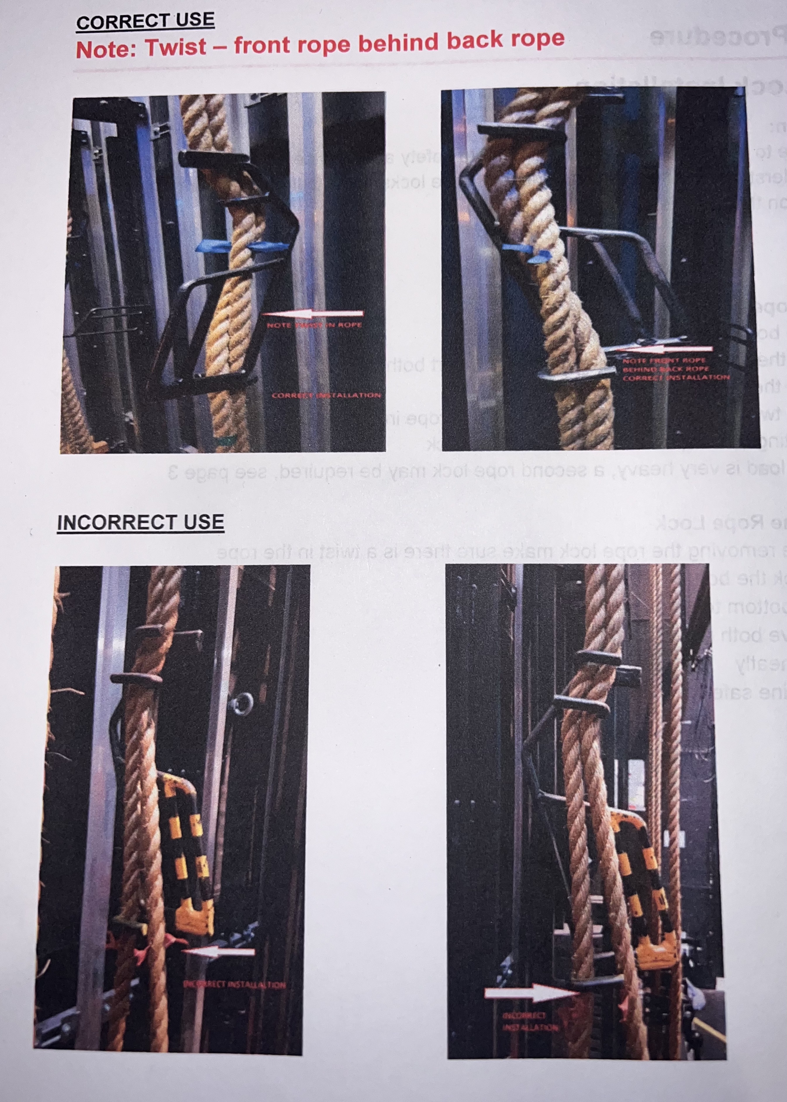
Applying Rope Locks
1. Grab both ropes in your hands
2. With the top of the lock facing the wall insert both ropes
3. Push the bottom part towards the wall
4. Put a twist in the rope by placing the back rope in front of the front rope
5. Inserting both ropes in the bottom of the lock
6. If the load is very heavy, a second rope lock may be required, see page 3
Removing the Rope Lock
1. Before removing the rope lock make sure there is a twist in the rope
2. Unhook the bottom of the lock
3. Push bottom towards the wall
4. Remove both ropes from top of lock
5. Store neatly
6. Move line safely -
Supervisor to complete: Friction rope lock use
- Competent
- Non-Competent
- Further training required - limited duties as trainee can proceed
-
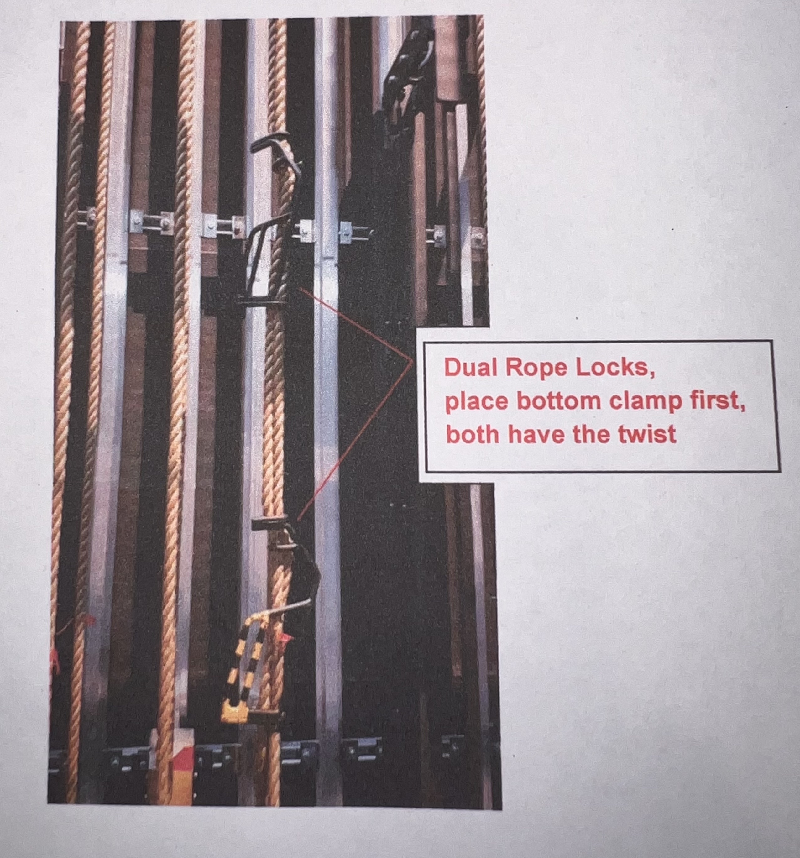
Use of dual friction rope locking devices for heavy loads
-
Use of dual friction rope locking devices for heavy loads
Under the supervision of the Fly supervisor or technical manger the trainee must demonstrate the following competency.
Applying Heavy Load Rope Lock
1. Install first rope lock at body height
2. Obtain small step ladder for second rope lock, ensure about 400mm gap between locks
3. Install second rope lock in the opposite direction of the first rope lock
Removing Heavy Load Rope Lock
1. Use small ladder to remove top rope lock first
2. Put a twist in the rope
3. Remove bottom rope lock
Included in this competency the trainee must also show a robust understanding of the use cases that could require dual locks and the importance of checking lines under load before lock removal. -
Supervisor to complete: Operation of dual rope friction locks
- Competent
- Non-Competent
- Further training required - limited duties as trainee can proceed
-
Demonstrate lock out procedures: Show / maintanence
-
Lock out procedure show & maintenance / damage conditions
Under the supervision of the Fly supervisor or technical manger the trainee must demonstrate the following competency.
The trainee is to describe at least 2 circumstances that might require a full lock out of one or more counterweight sets as well as,
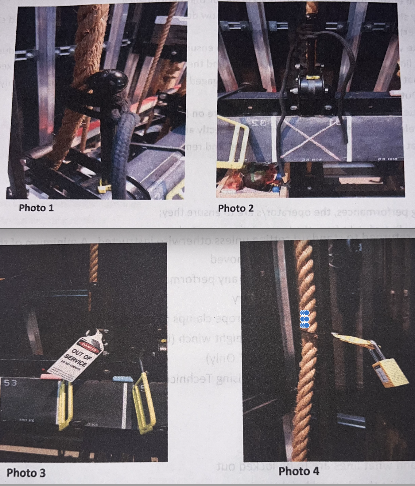
1: Using a piece of 10mm white or black cord tie the top of the Lever rope lock handle (in its locked or UP position) to the front manila hauling rope.
2: Indicate lockout on that lines chalkboard by placing a large pink X
3: Confirm requirement to note lockout in report and to notify duty technical manager
For servicing or damaged lines:
4: Determine which part of the system is damaged and possible cause/s of the damage - take photos or video for records (add to Fly operations report in Iauditor)
5: Ensure the damaged components are secured safely and pose no danger to personnel or fouling on other operational equipment.
6: Lock the line as per show conditions above
7: Collect a lockout padlock and 'Out of Service' tag from tech office
8: Attach out of service tag *remember to sign and date the tag
9: Attach the padlock
10: Fill in CoGB Hazard/Incident Notification Form and BV&E equipment fault report and attach to the event report
11: Notify Team Leader - Technical Services -
Supervisor to complete: Lockout Procedures
- Competent
- Non-Competent
- Further training required - limited duties as trainee can proceed

Conclusion
-
Has the trainee exhibited a competent level of practical and theoretical knowledge to participate in the operation of the counterweight fly system?
-
Supervisors recommendations or notes if any for technician to develop further based on todays induction
- Exhibited a high level of competency and comprehension
- Trainee has passed the induction but needs to continue training to ensure wholistic competency
- Trainee may be considered a provisional operator and assistant for fly operations with further follow up required
- More detailed notes required
-
What limits if any or follow up is required subsequent to this induction?
-
Pleas describe you notes and recommendations to assist the further development and competency moving forward
undefined
-
Name and signature of induction supervisor
-
Signature
-
Name and signature of inductee
-
I acknowledge that counterweight fly systems are complex, high risk systems that require ongoing training and maintenance. This induction is intended to give me the information and knowledge to participate in fly operations but is not an exhaustive training course and that i have the responsibility to know my own limits and to seek assistance when required.


