


Page de titre
-
Effectué le
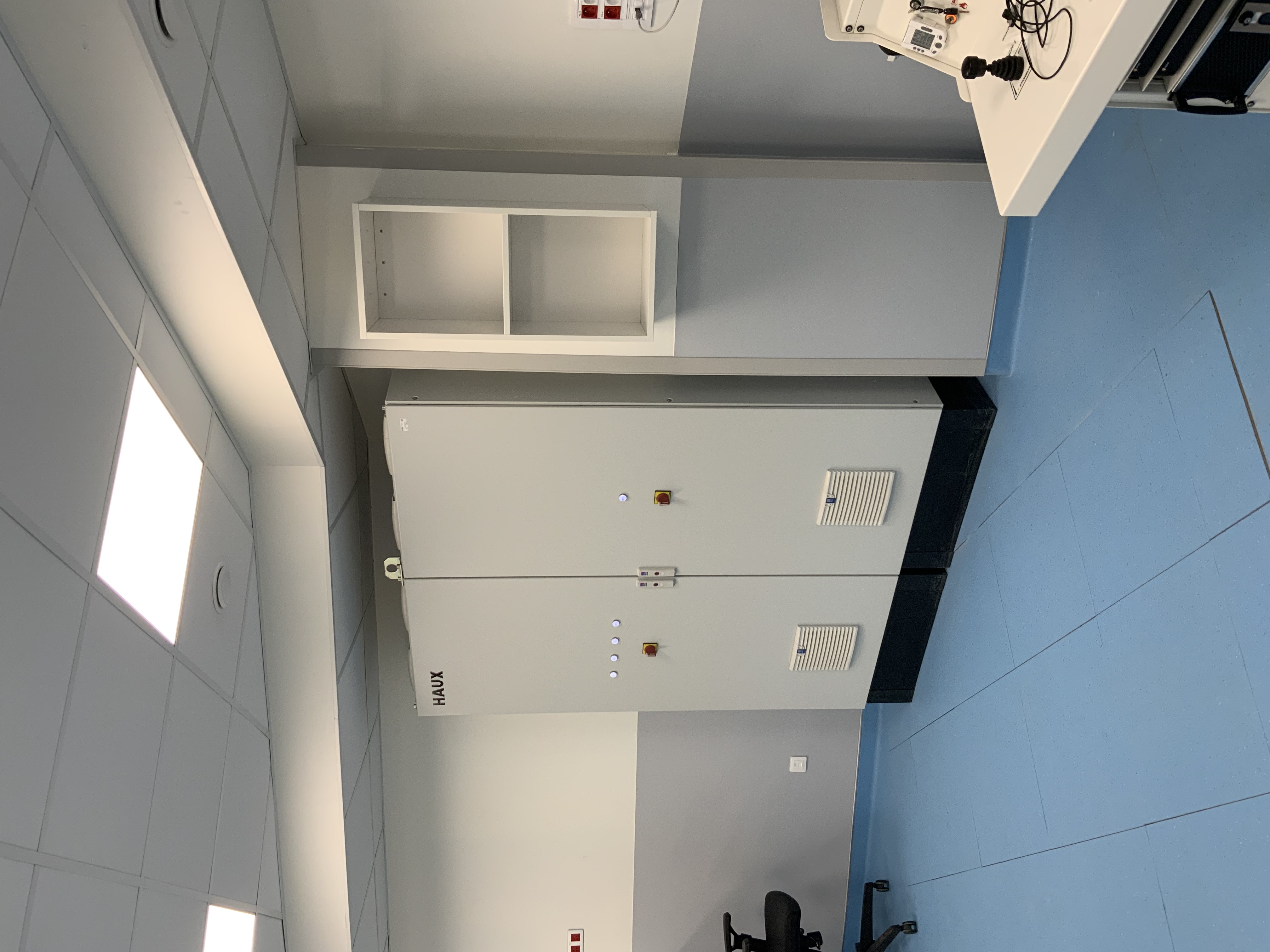
PIÈCE PRINCIPALE
-
-
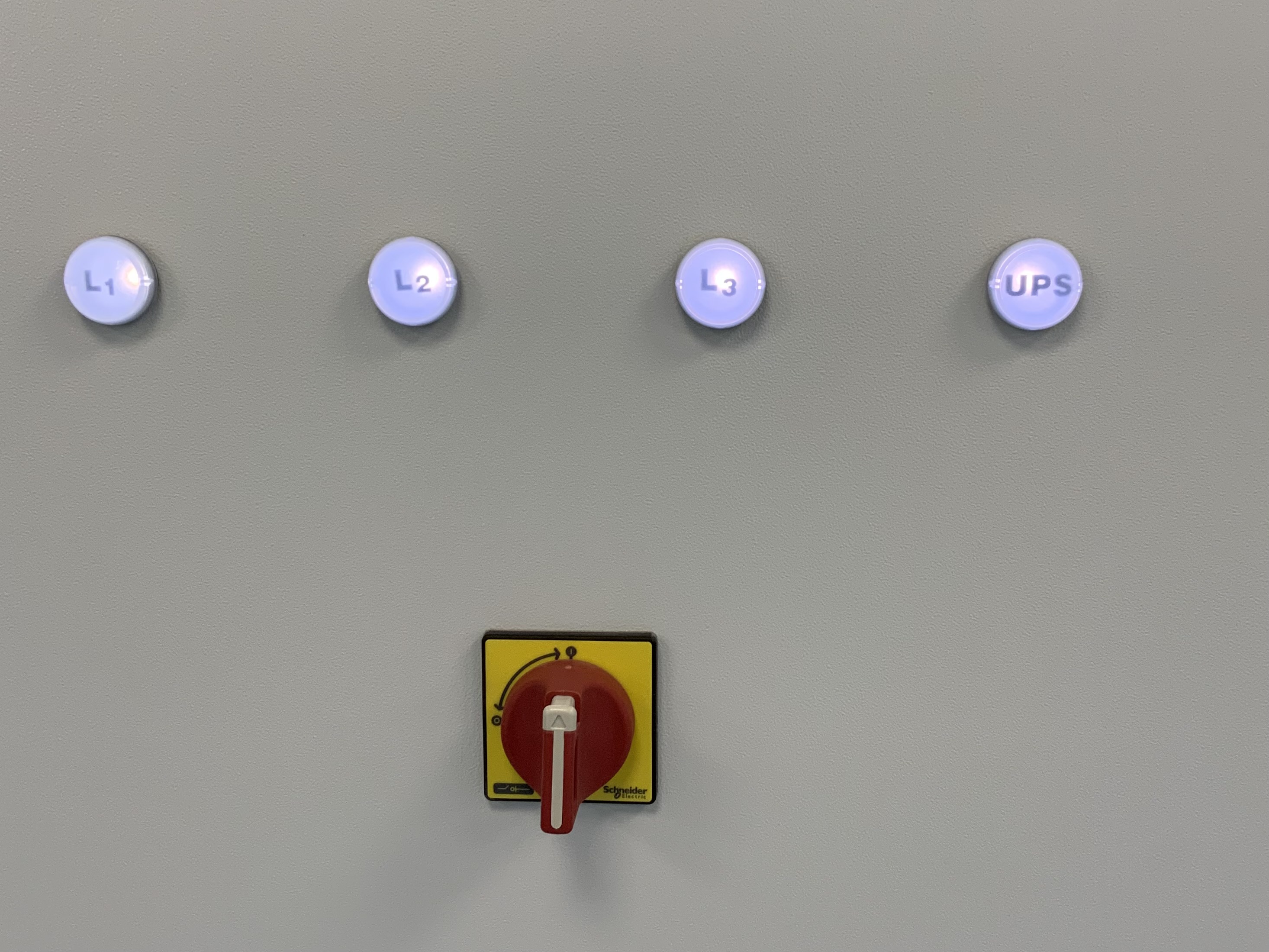
VOYANTS L1 L2 L3 UPS Allumés
-
-
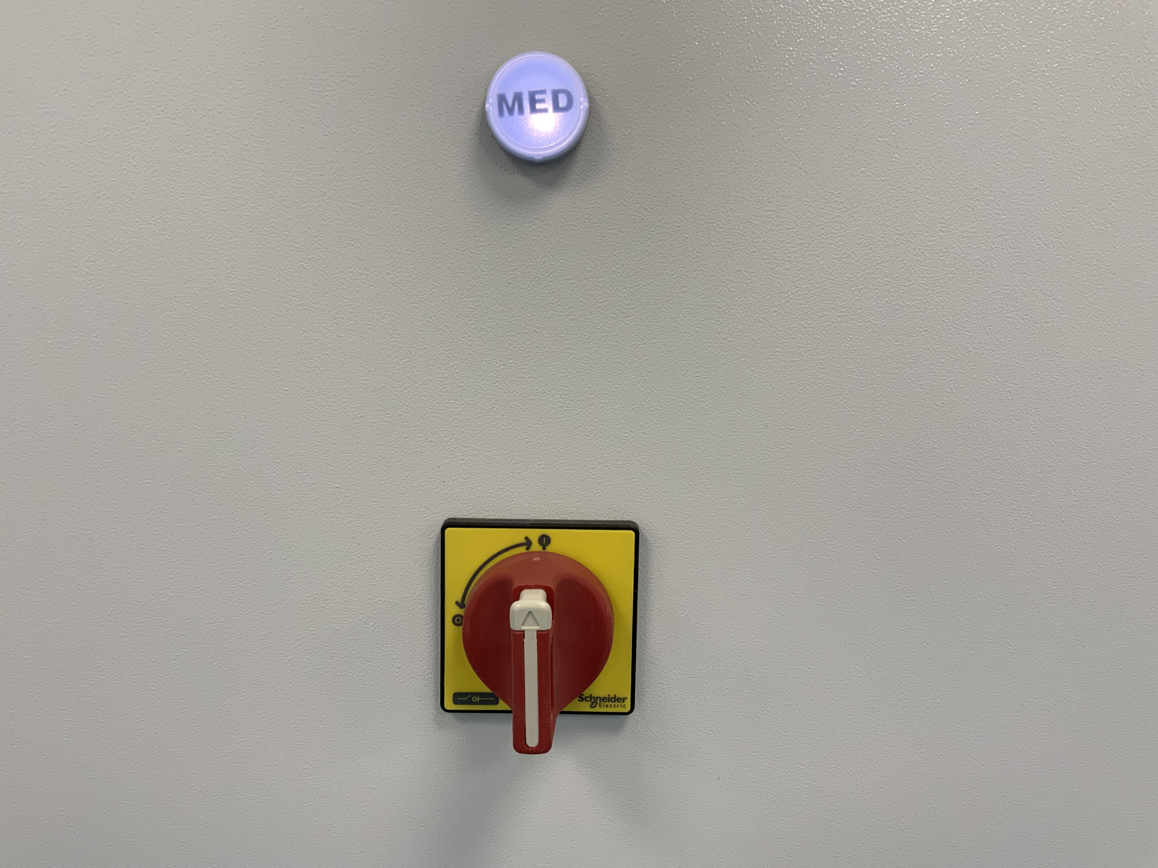
VOYANT MED Allumé
-
PUPITRE DECOMAT
-
-
Interrupteur allumé
-
-
Ordinateur Décomat 1 & 2 : Allumés
-
-
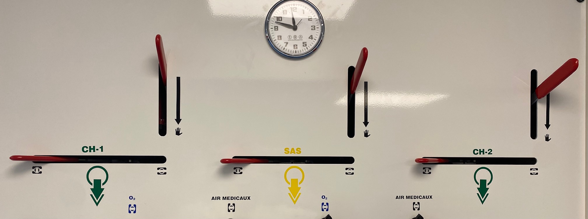
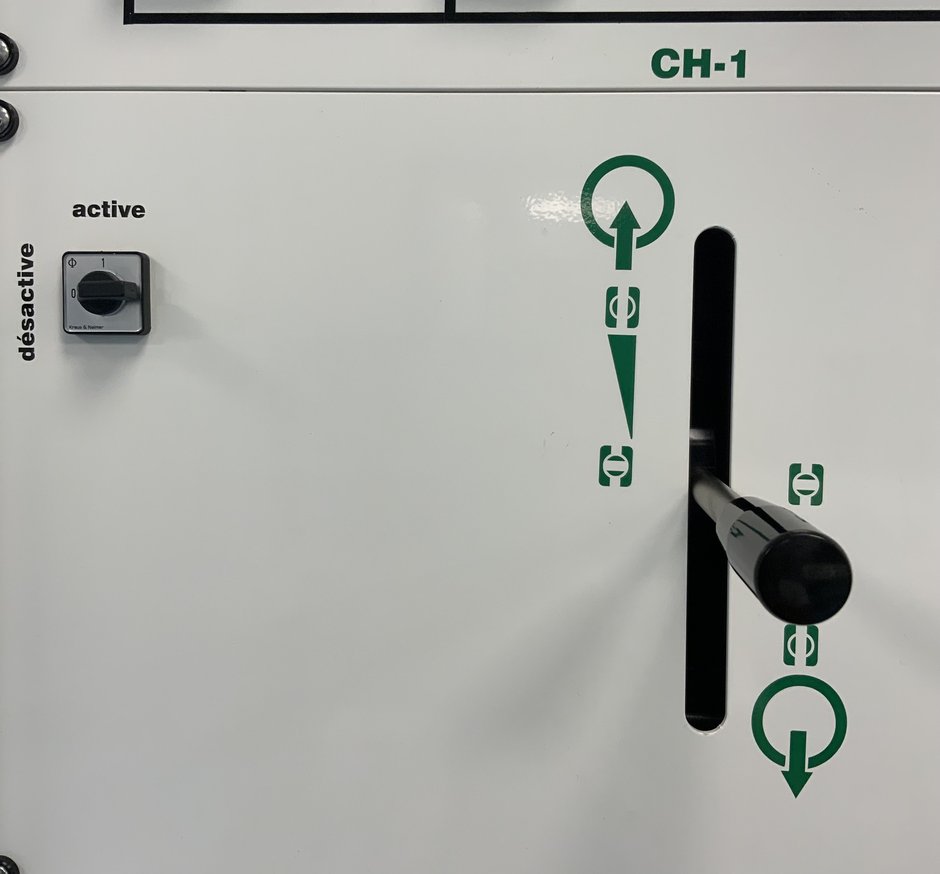
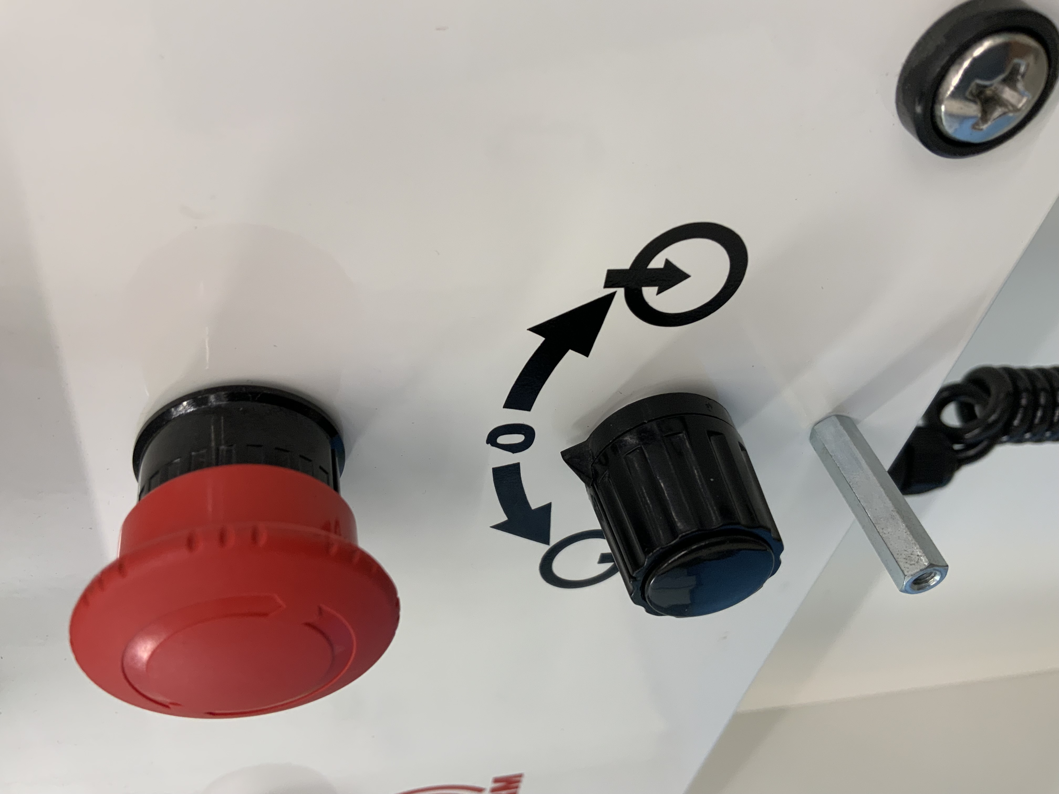
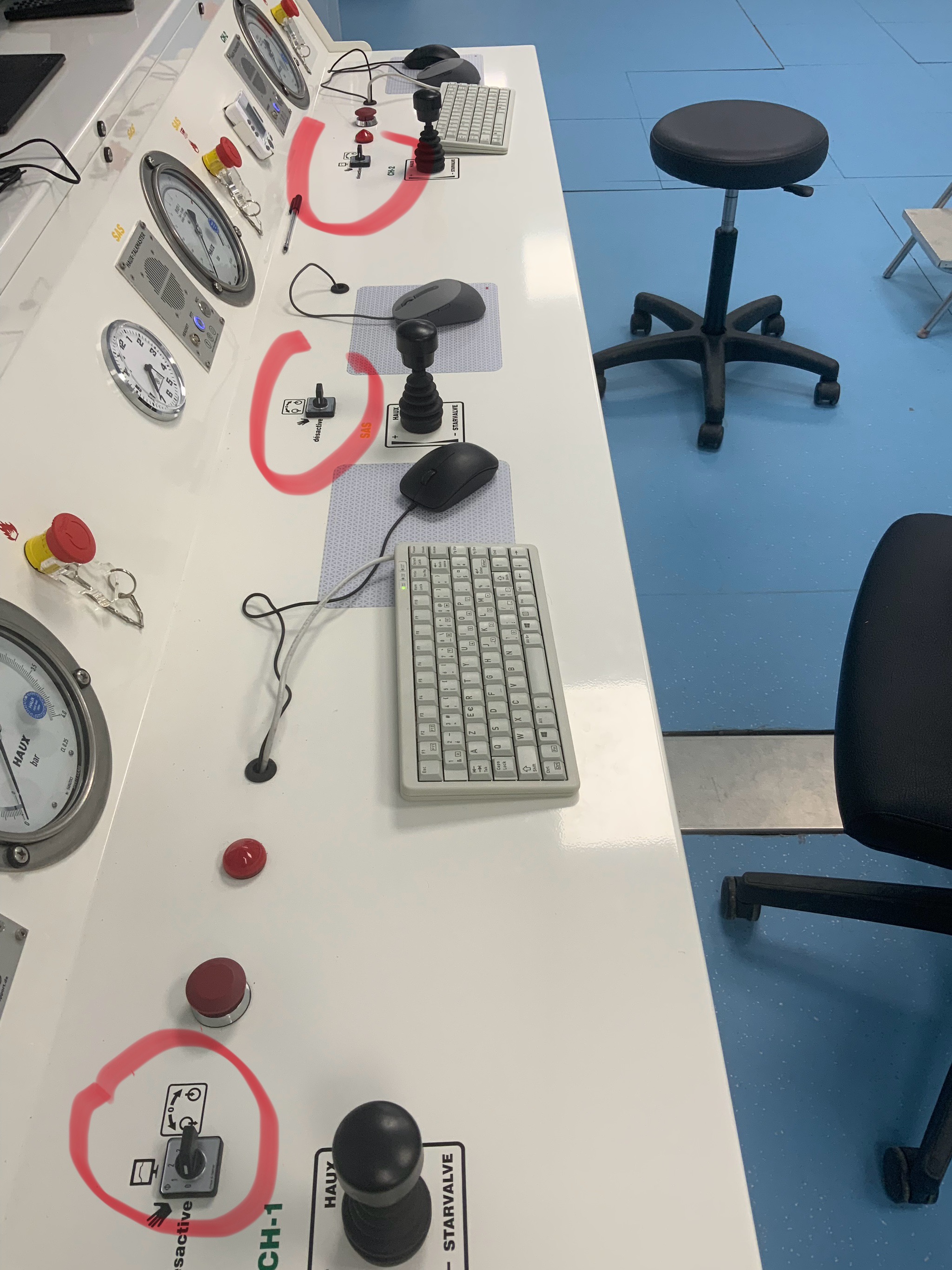
CH 1 : Decomat désactivé & Joystick au milieu
-
-
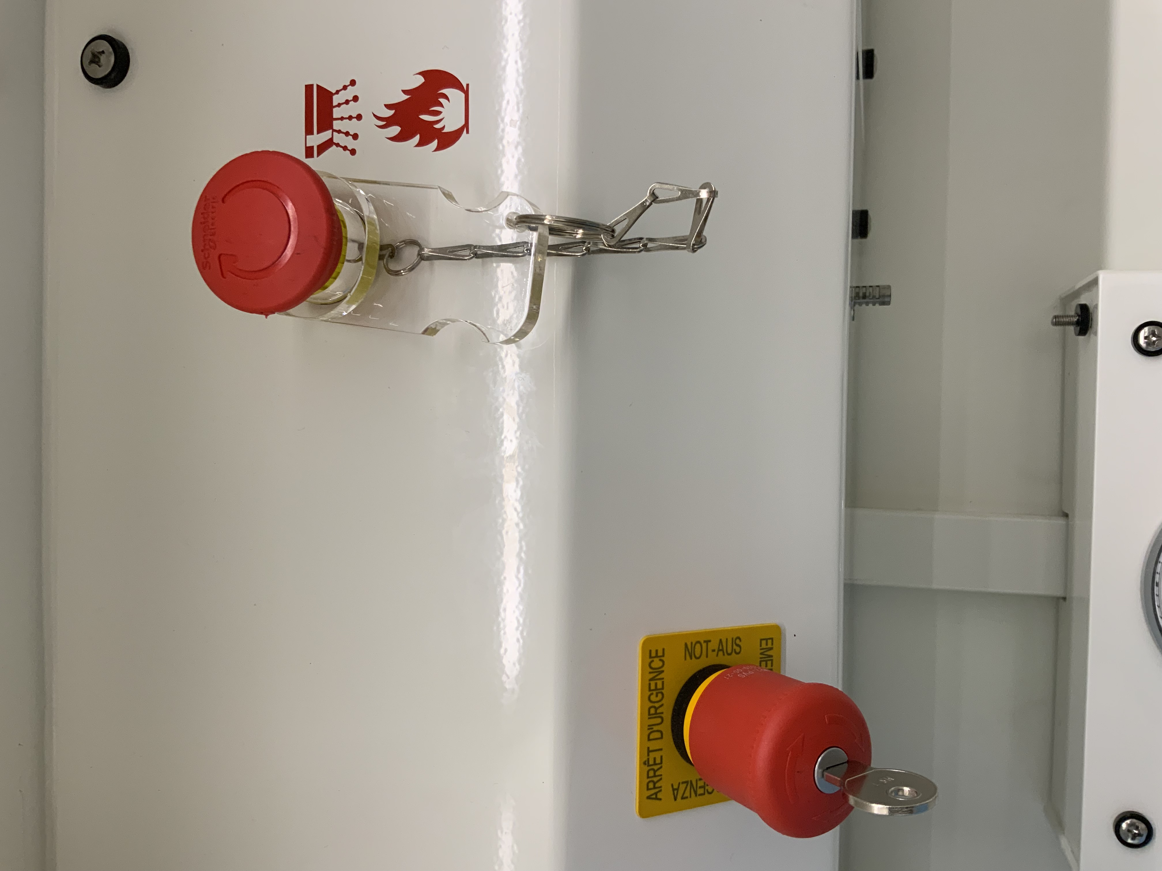
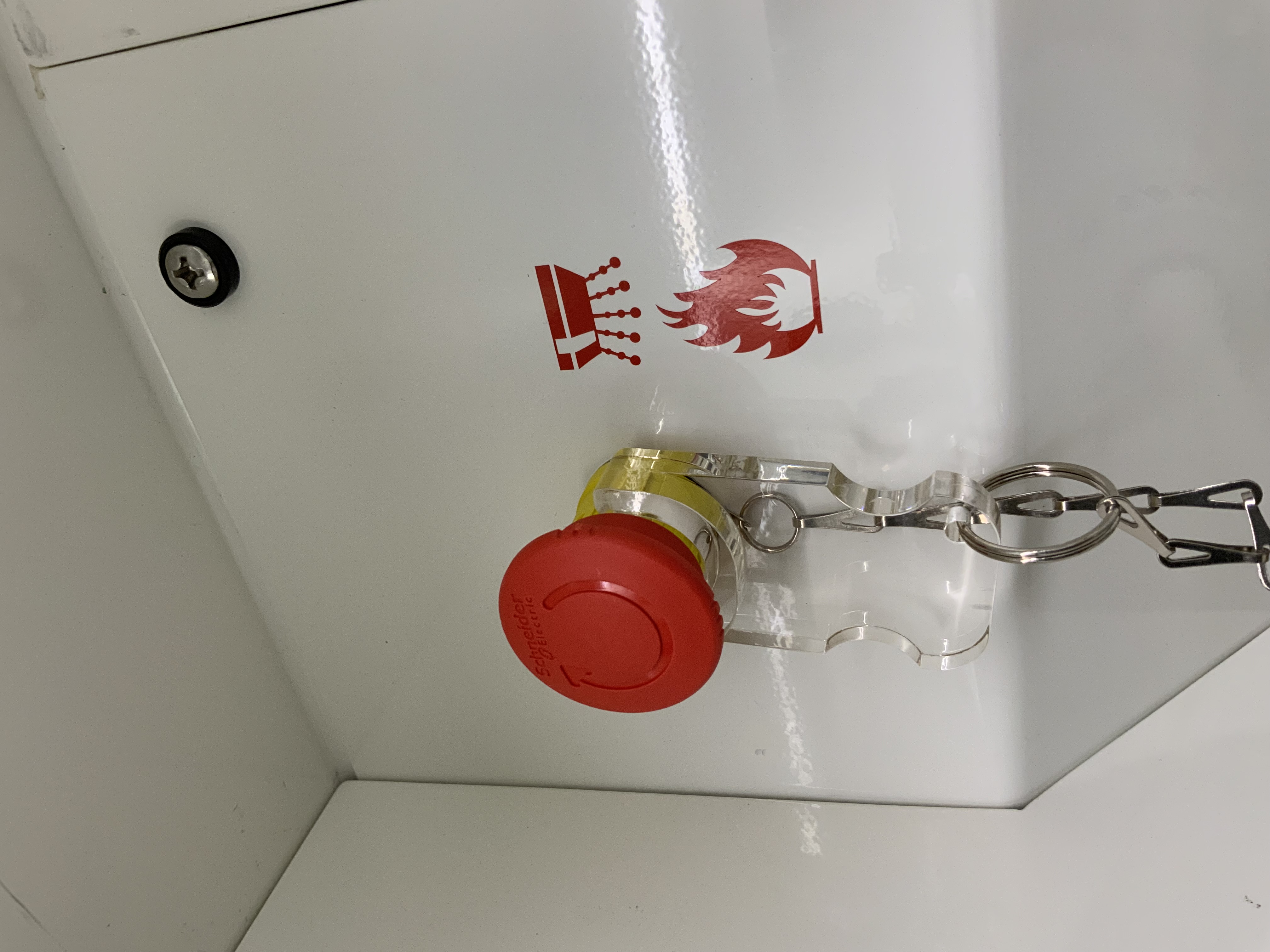
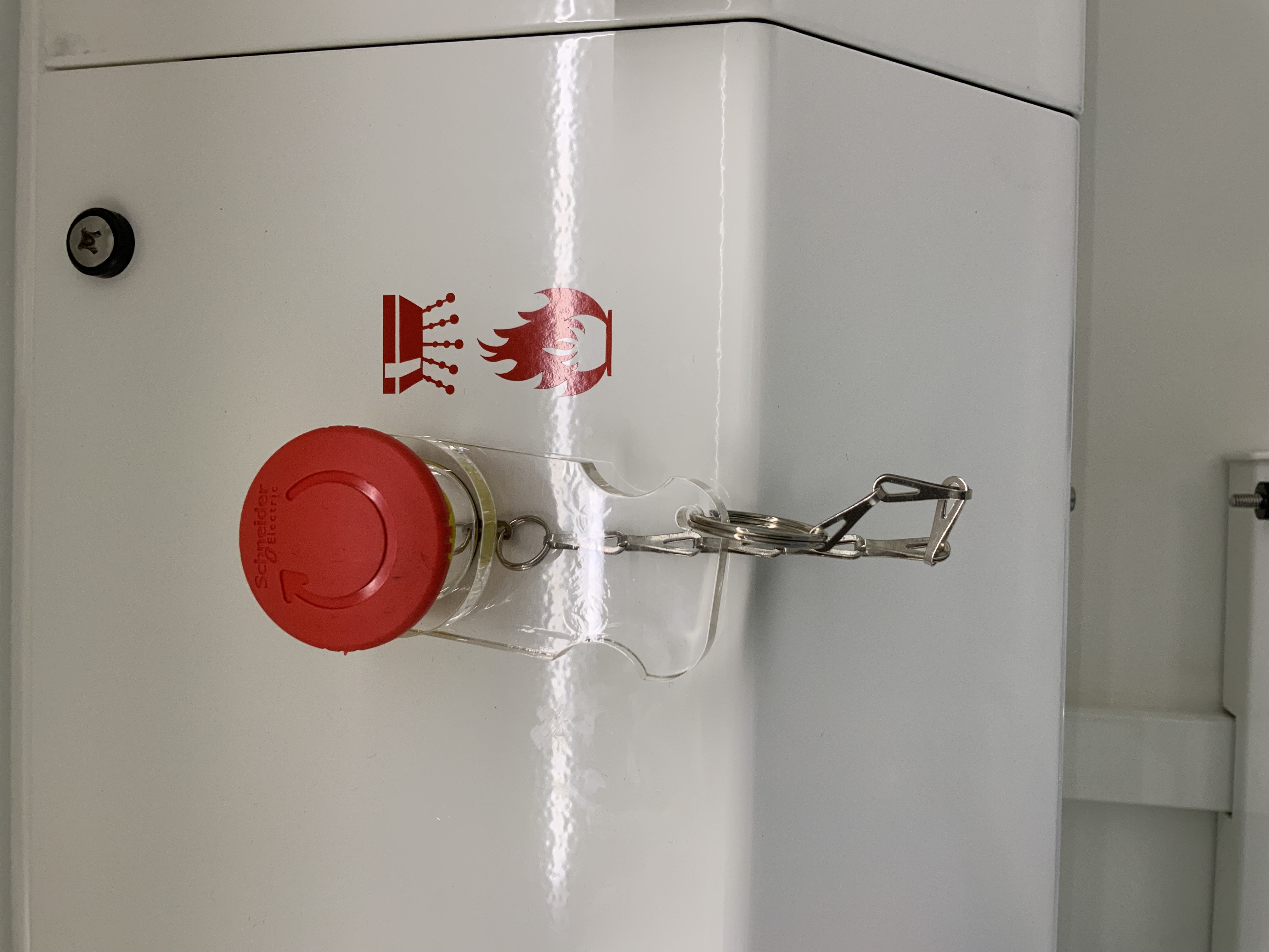
CH 1 : Incendie CLEF ET BOUTON OK
-
-
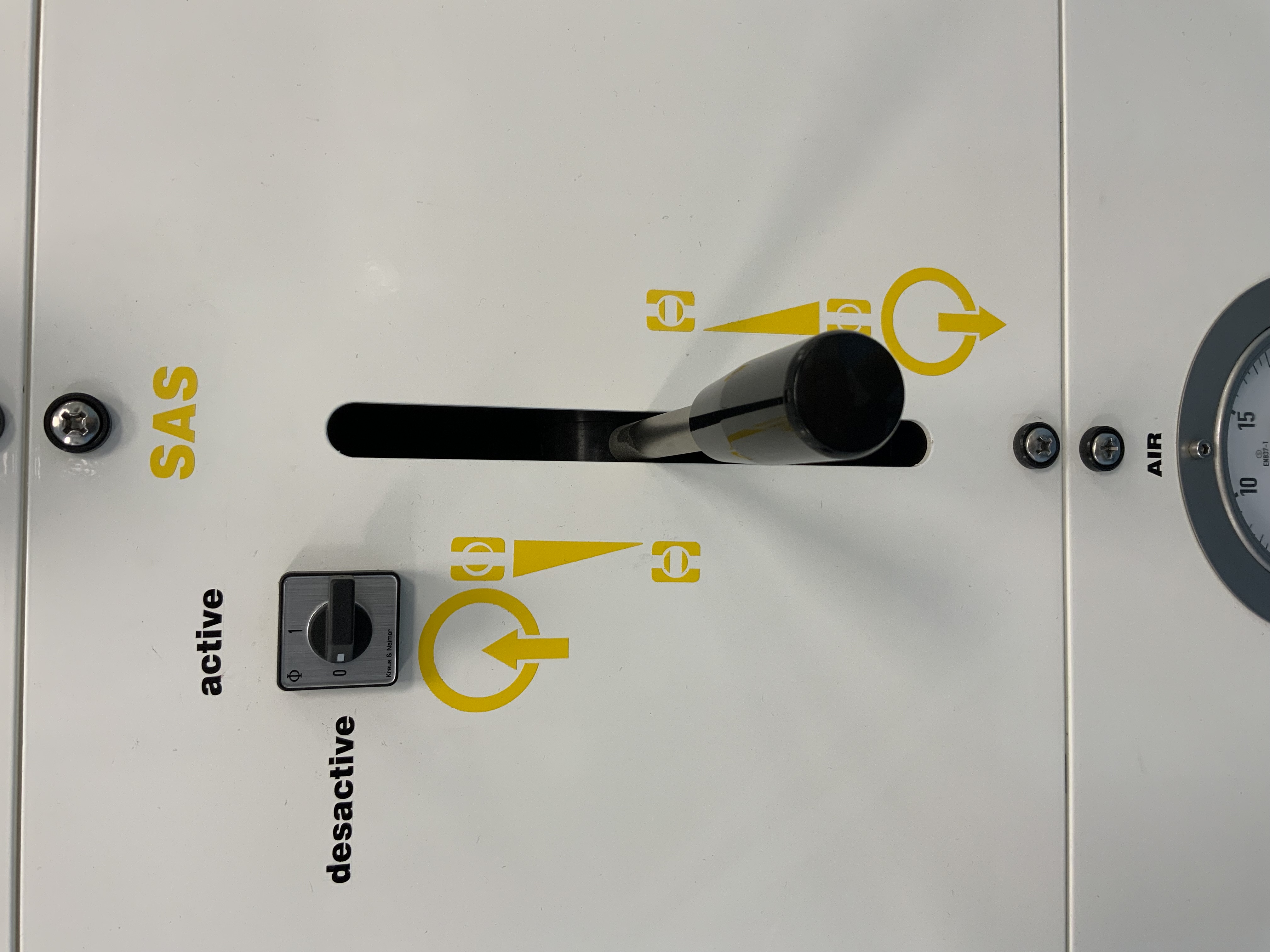
SAS : Décomat désactivé & Joystick au milieu
-
-
SAS : Incendie CLEF et BOUTON OK
-
-
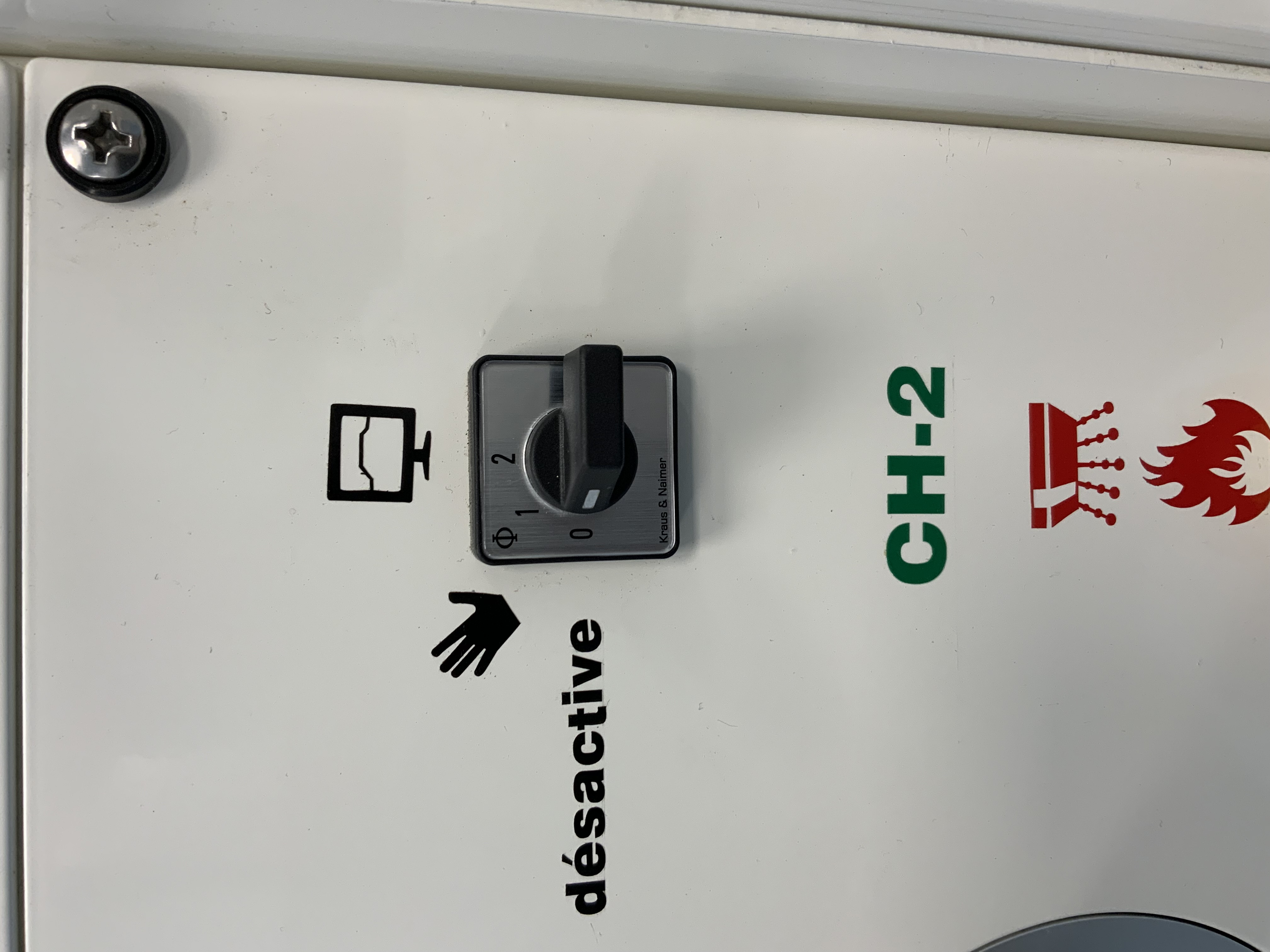
CH 2 : Décomat désactivé & Joystick au milieu
-
-
CH 2 : Incendie CLEF & BOUTON OK
-
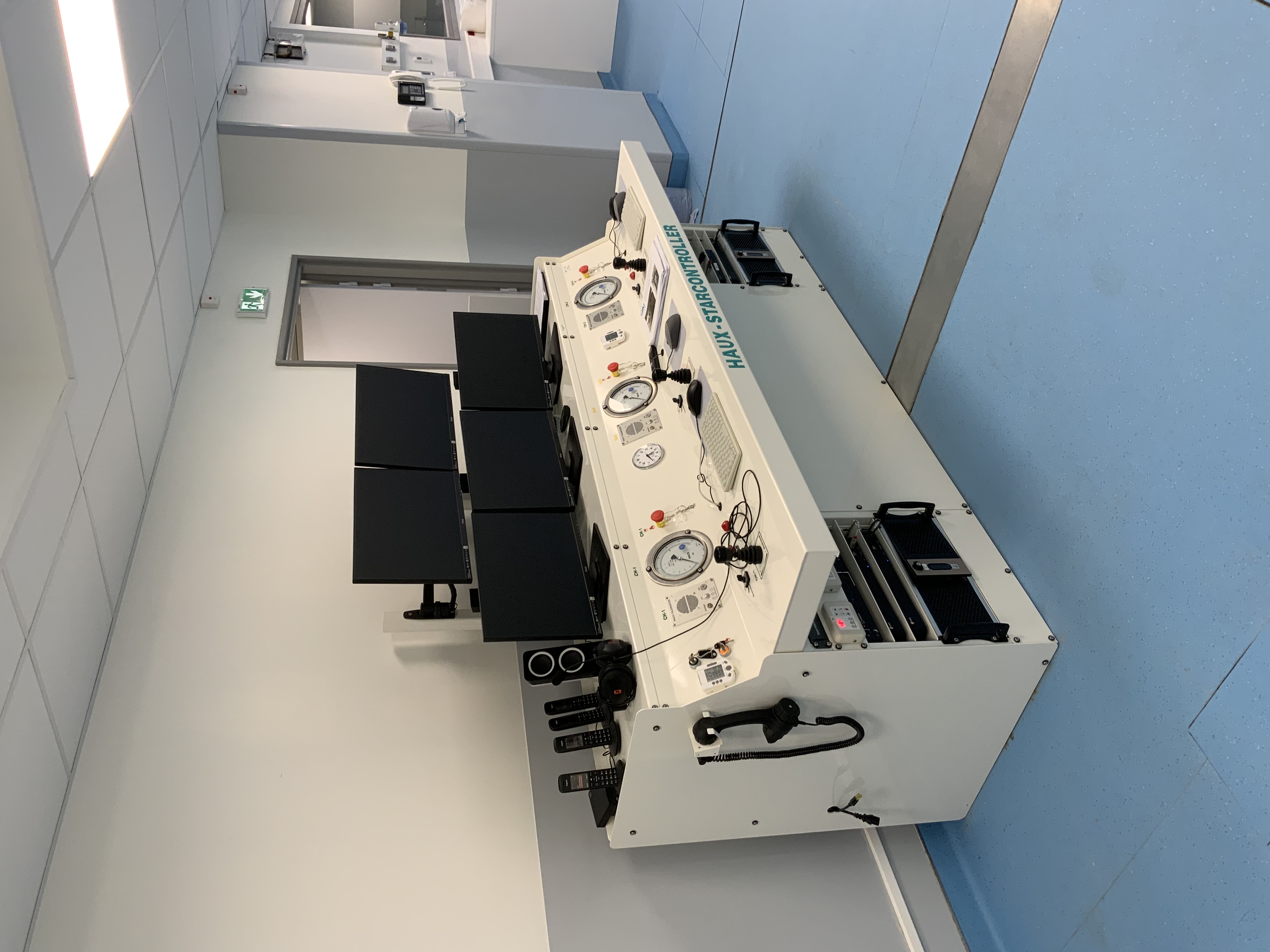
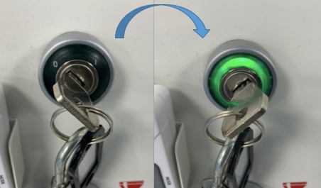
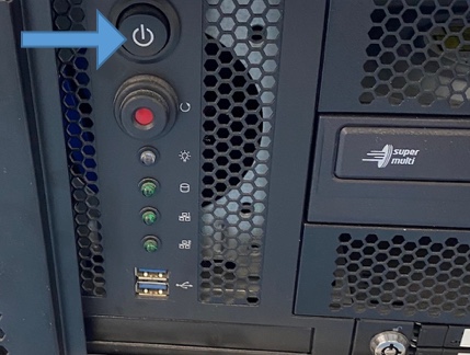
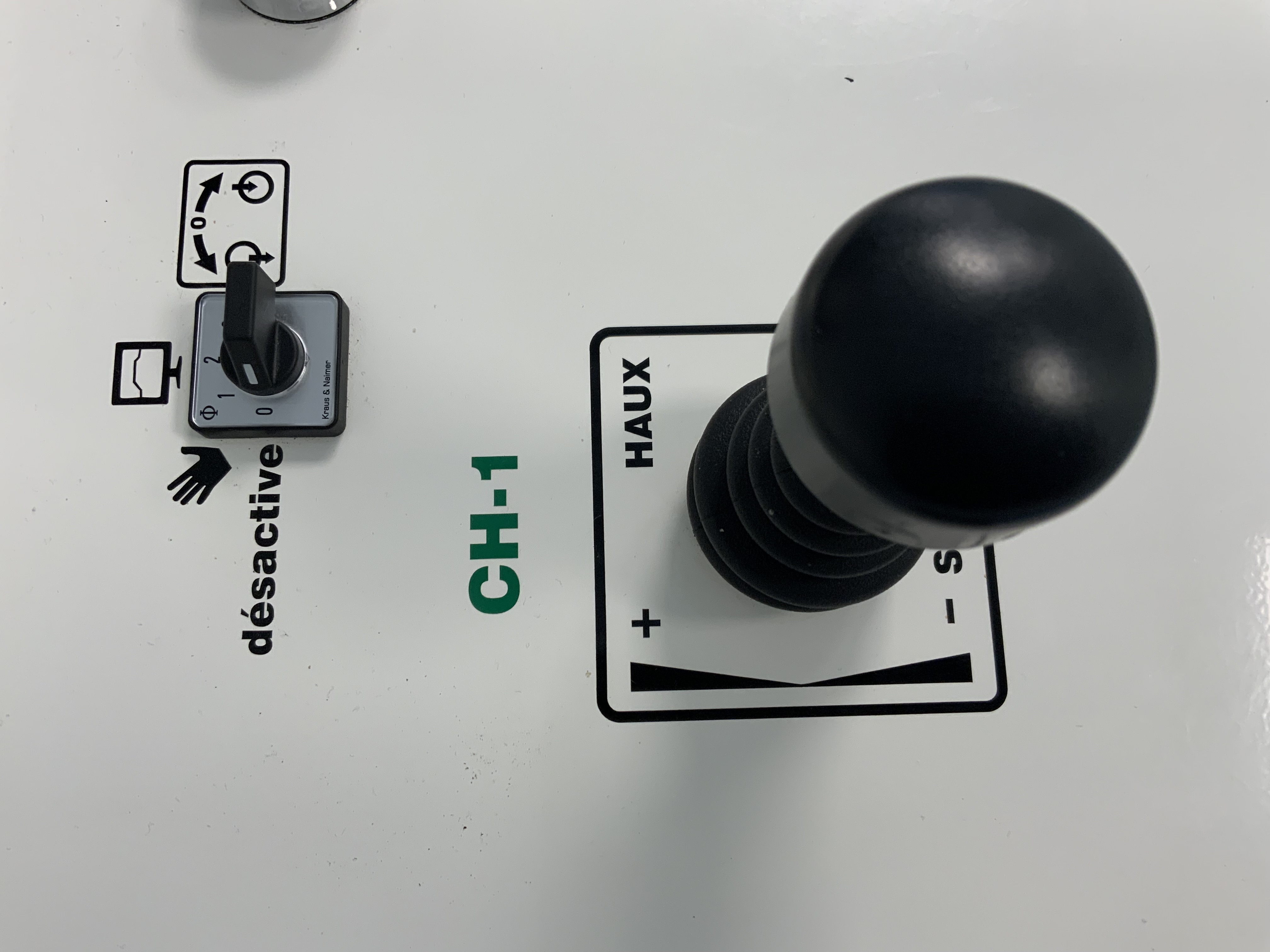
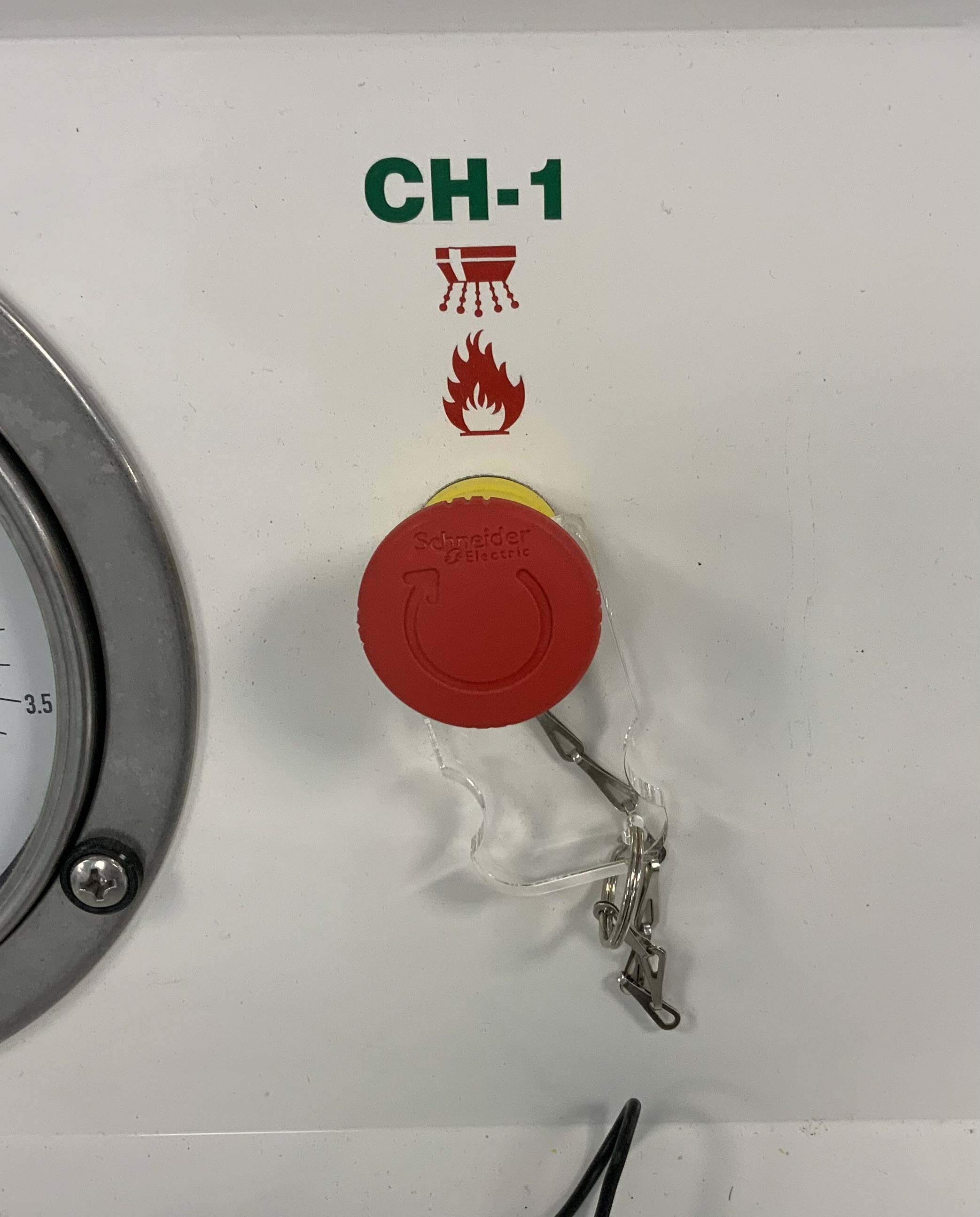
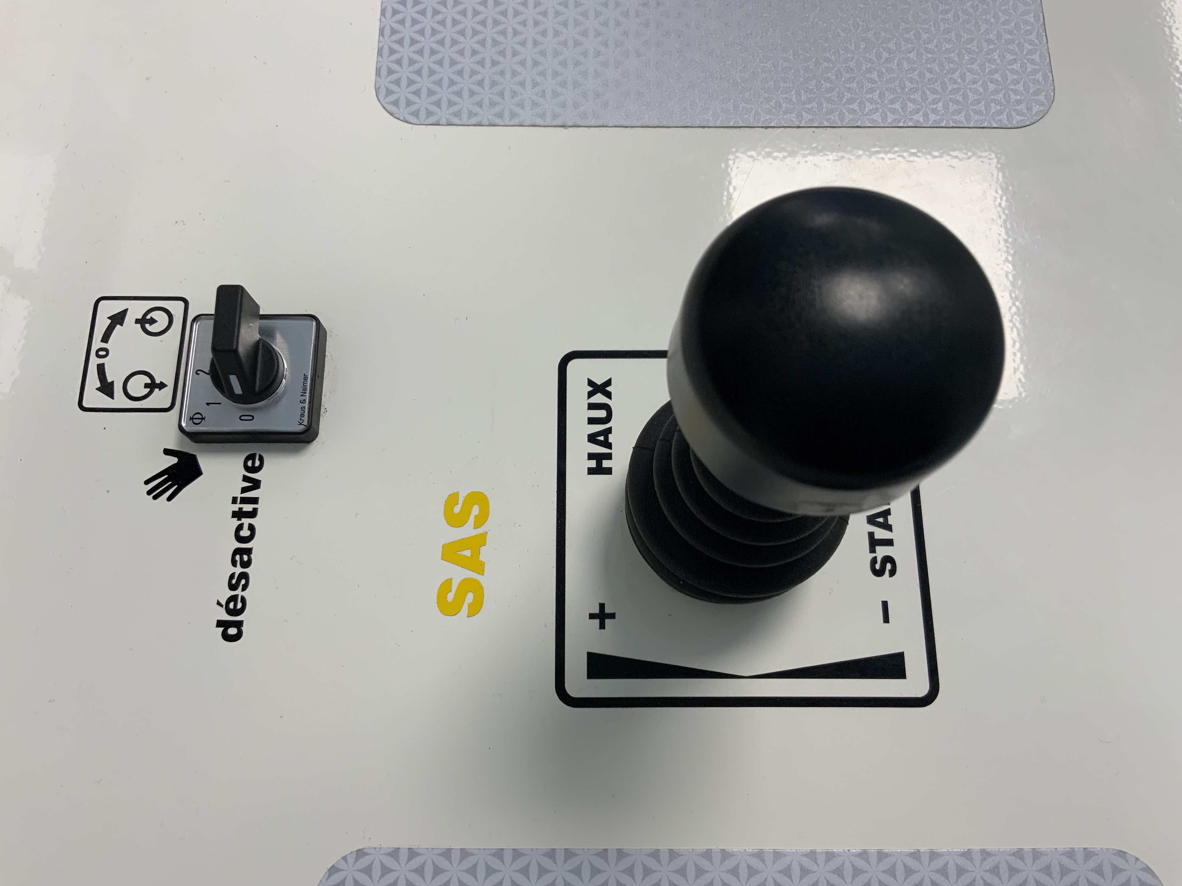
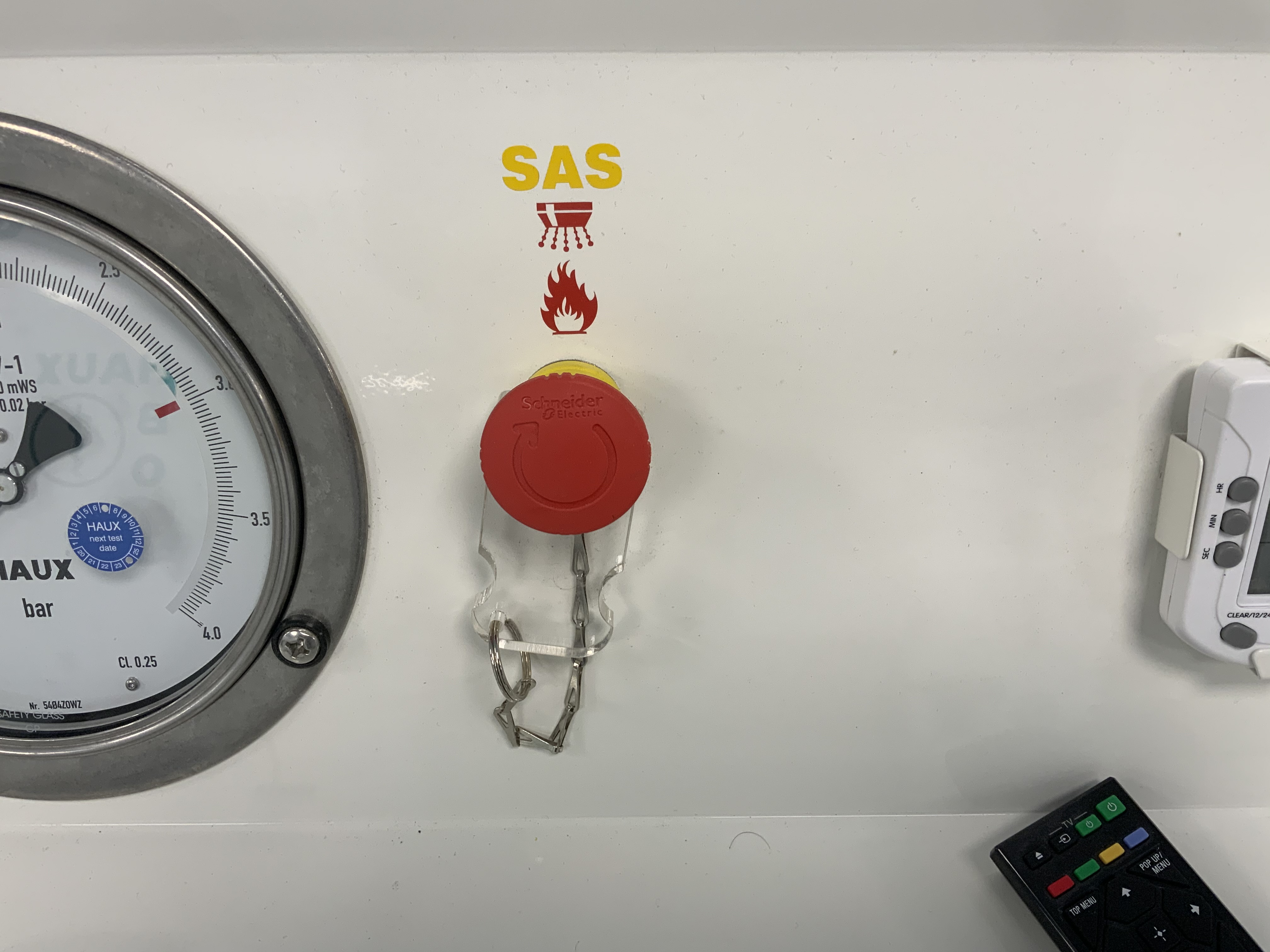
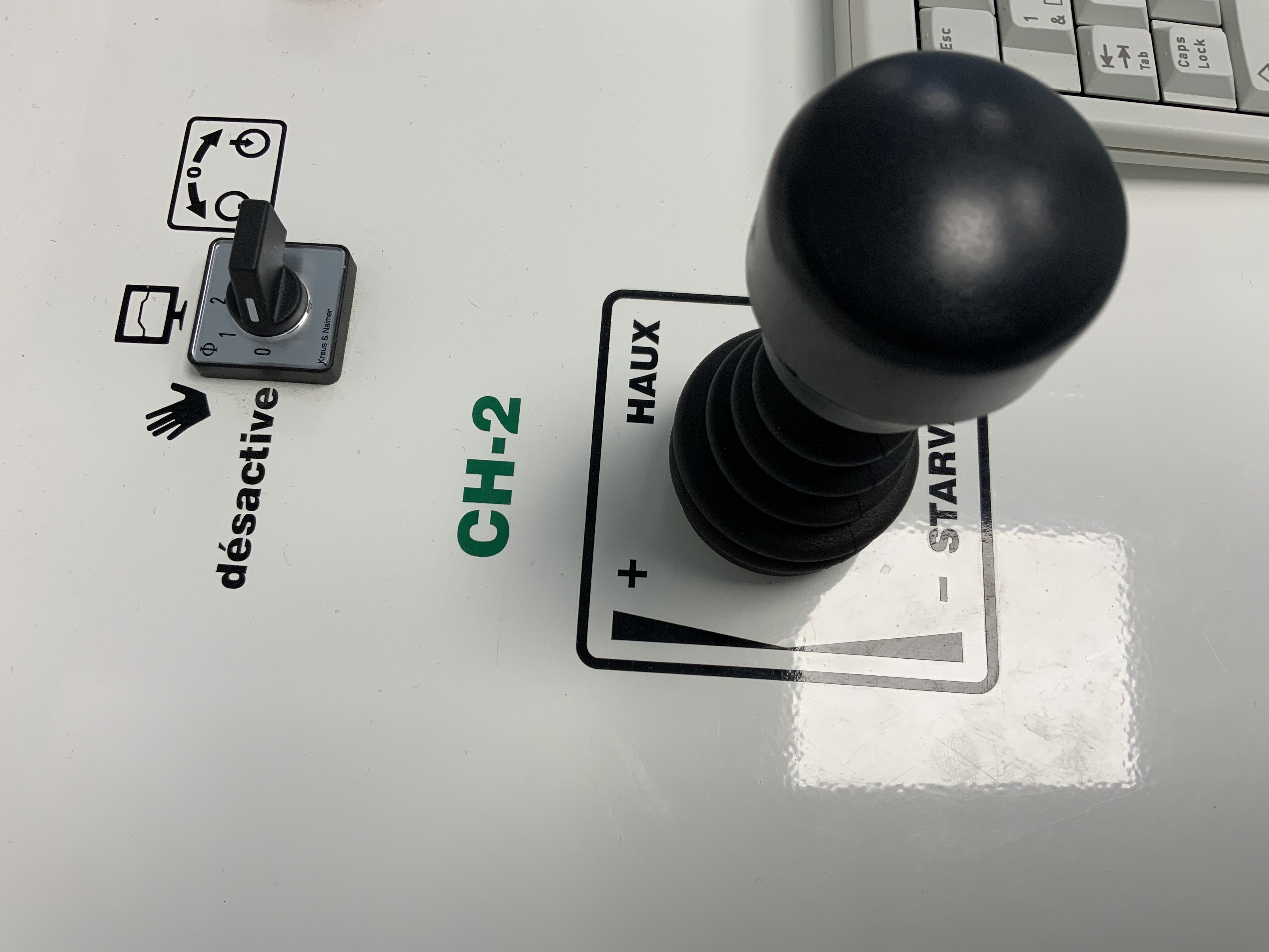
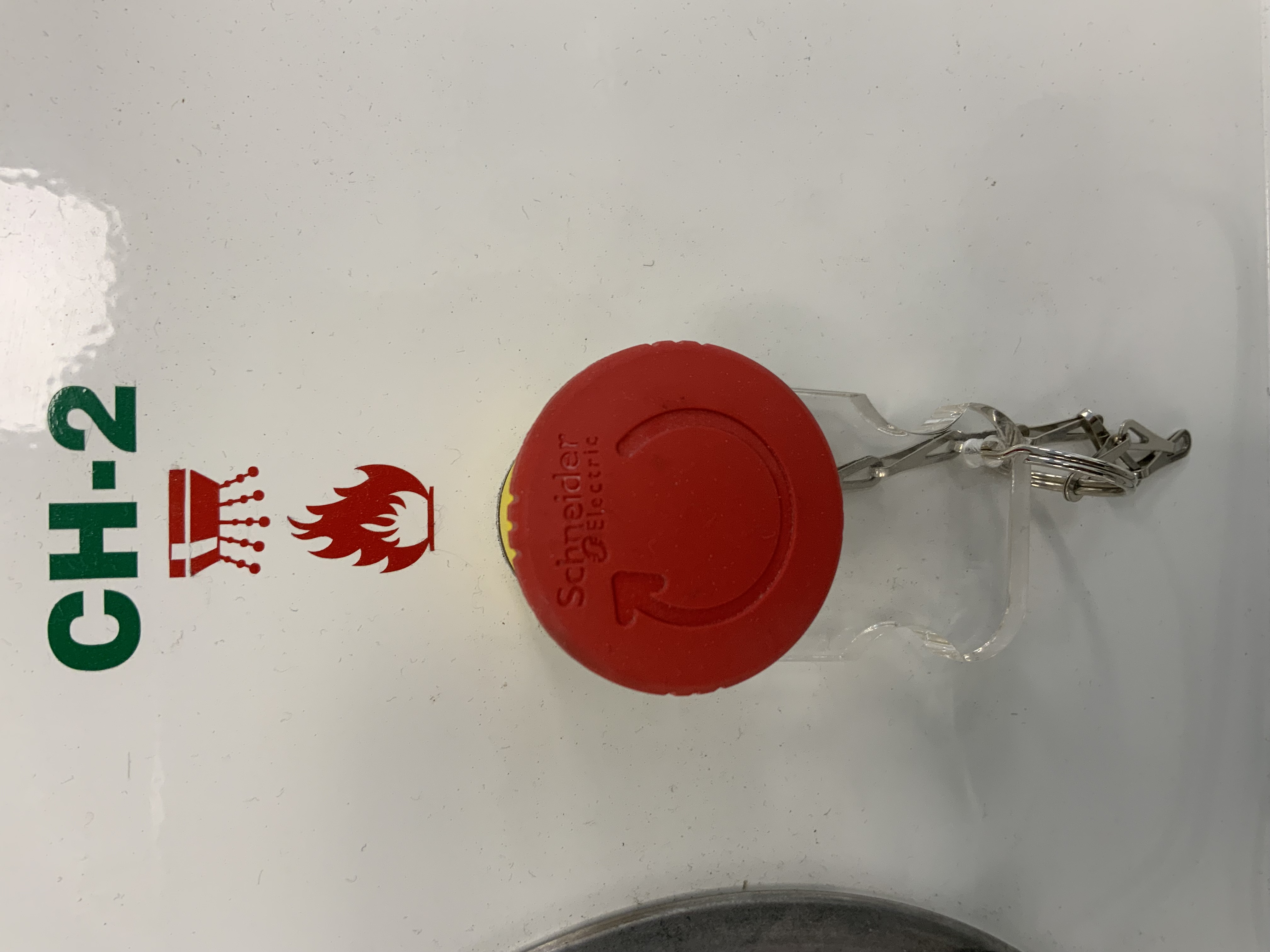
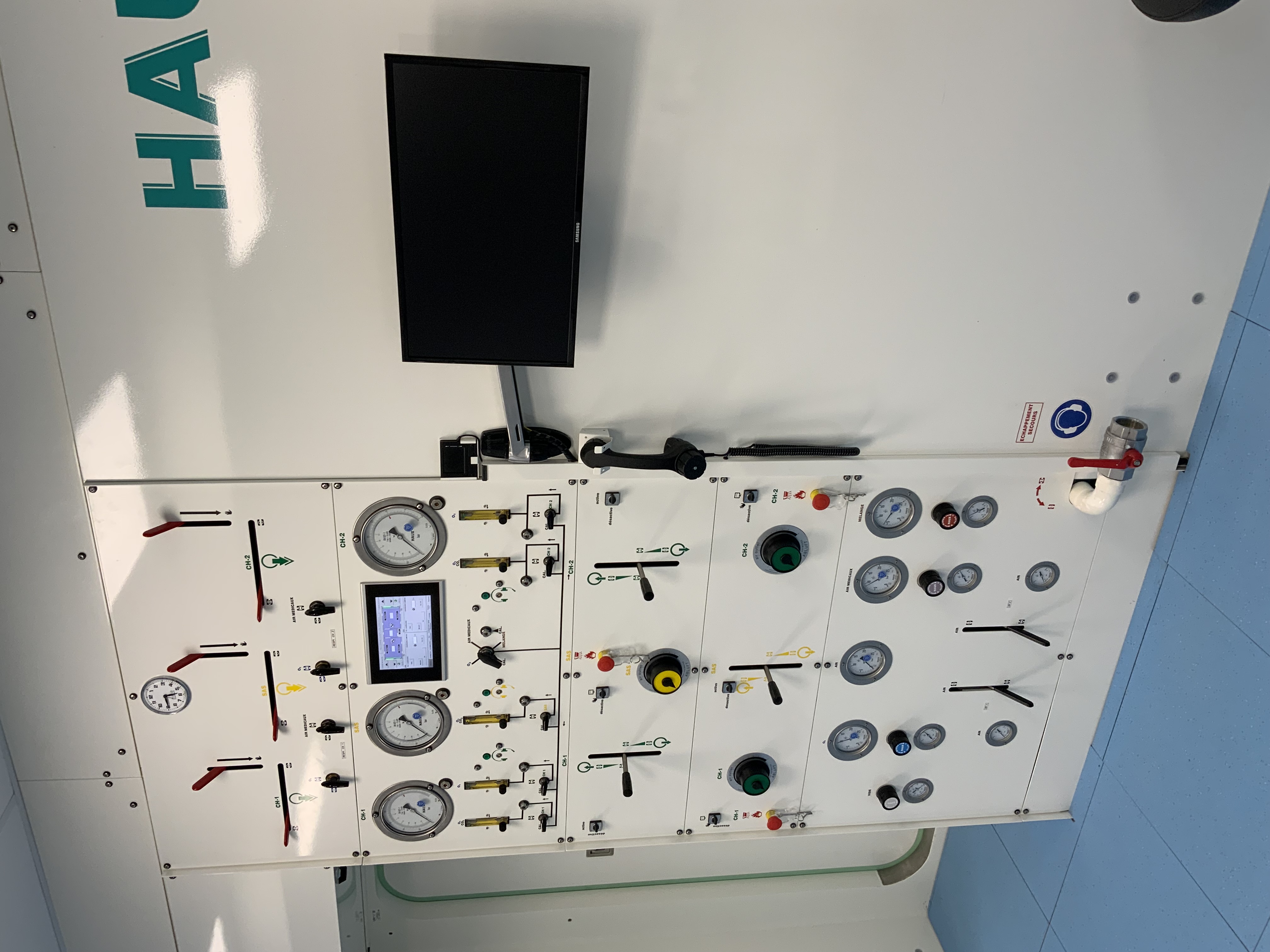
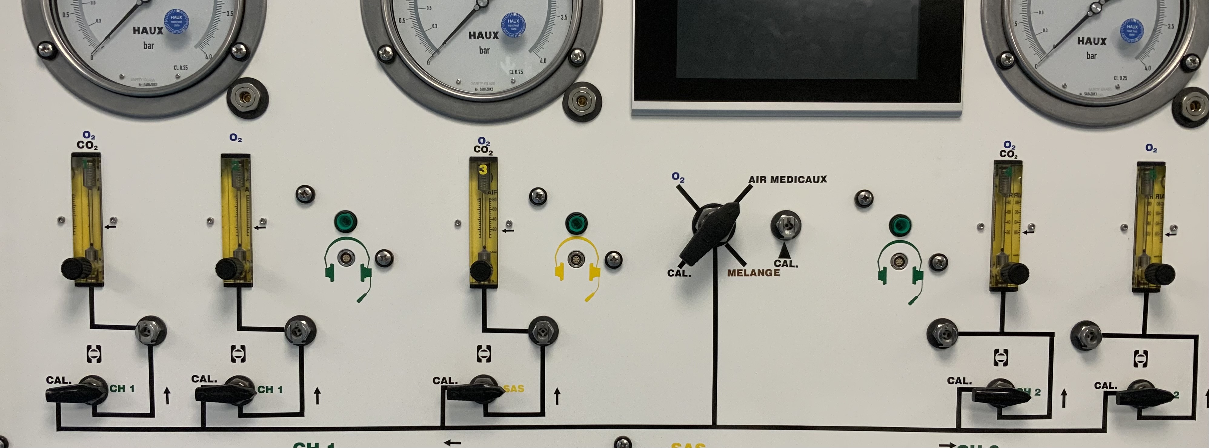
TABLEAU PNEUMATIQUE (TCPN)
-
Pupitre
-
Vannes échappement rapides fermées : CH 1 + SAS + CH 2
-
-
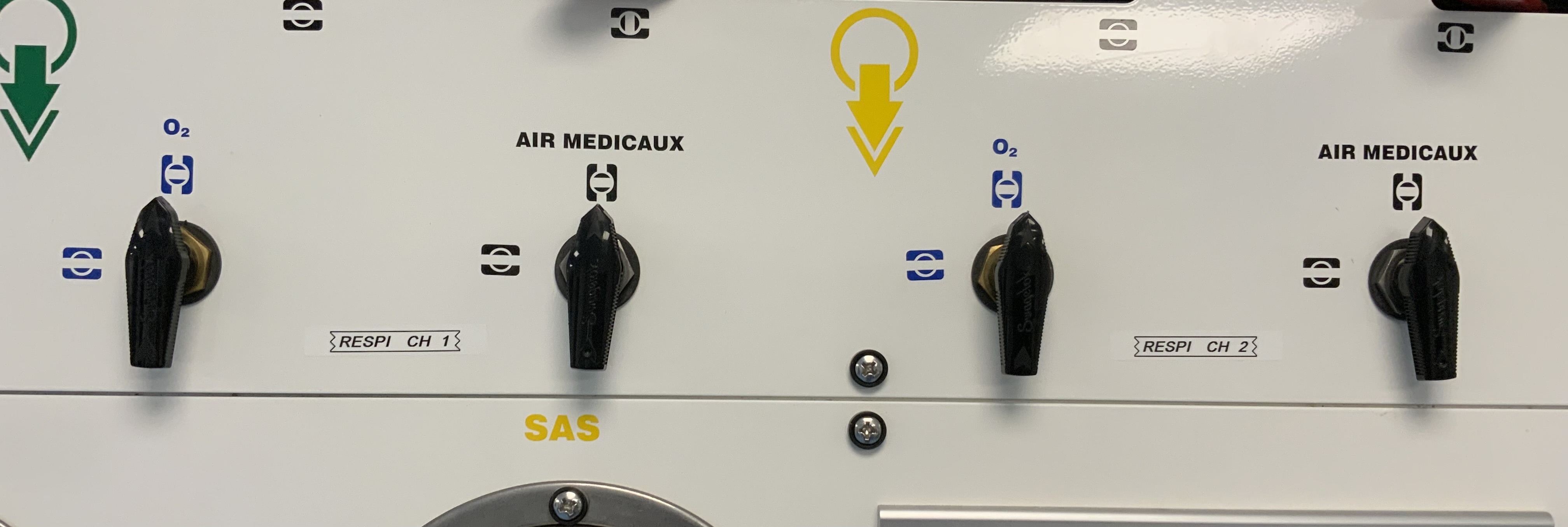
Vannes respirateurs O2 & fermés : CH 1 + CH 2
-
-
Bus : fonctionnel
-
-
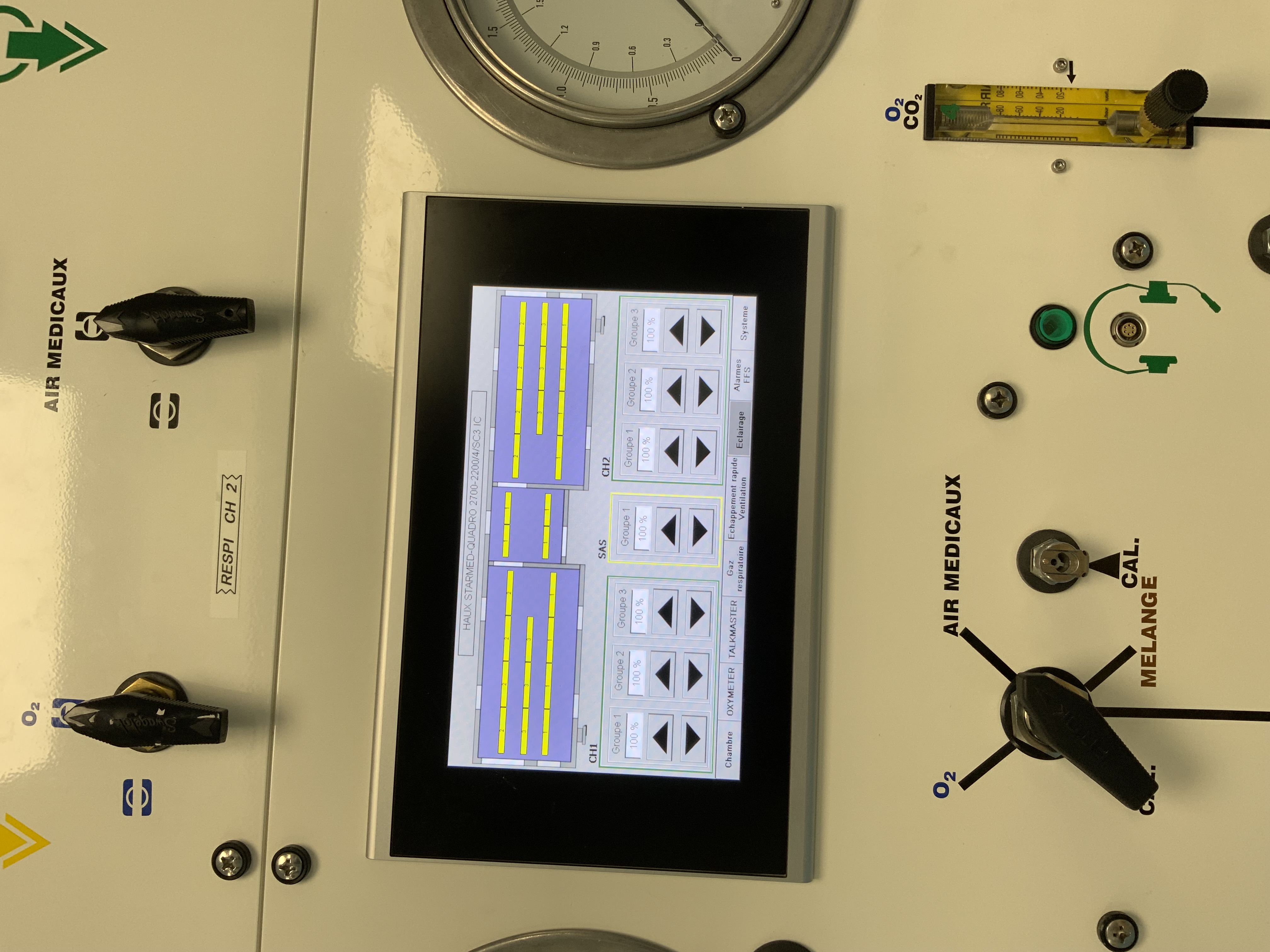
Analyse des gaz sur CH 1 + SAS + CH 2 : sur AIR
-
-
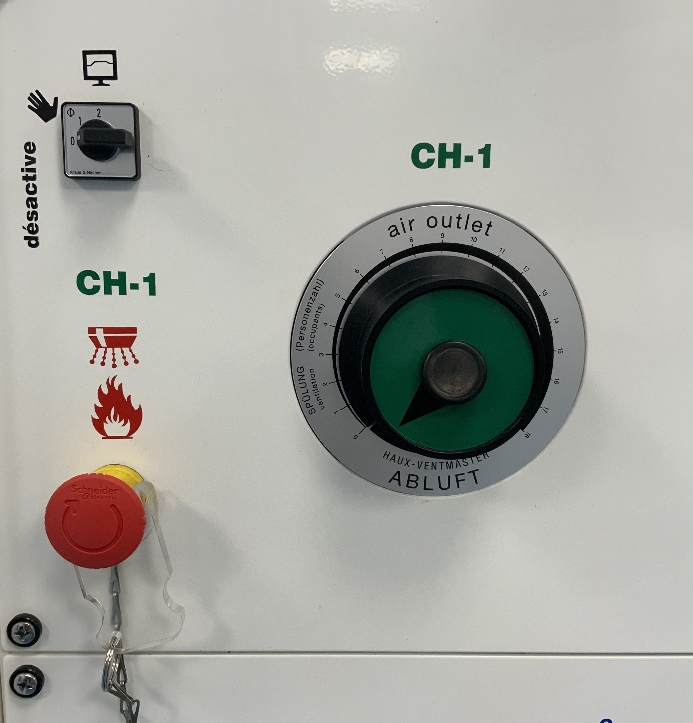
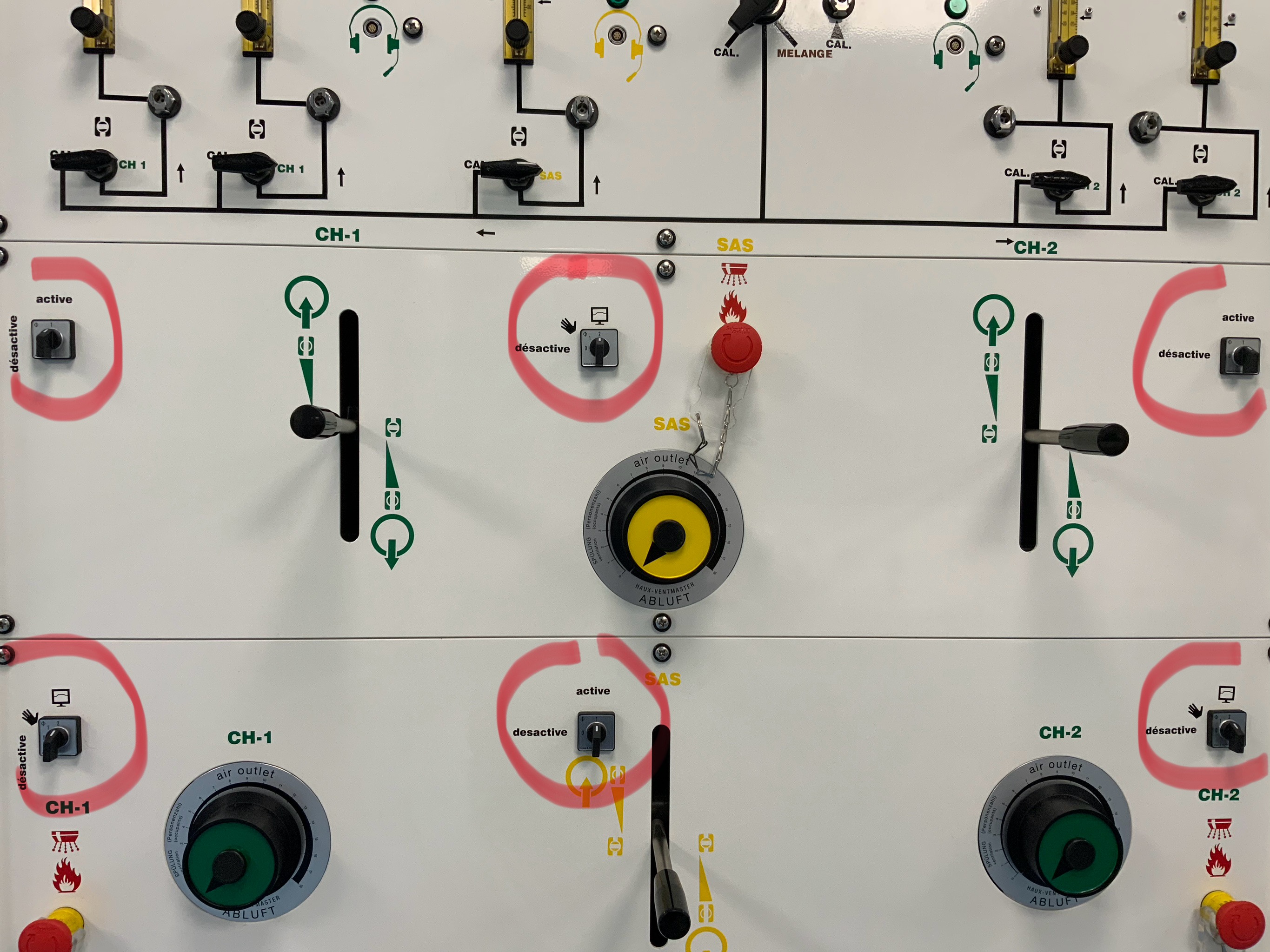
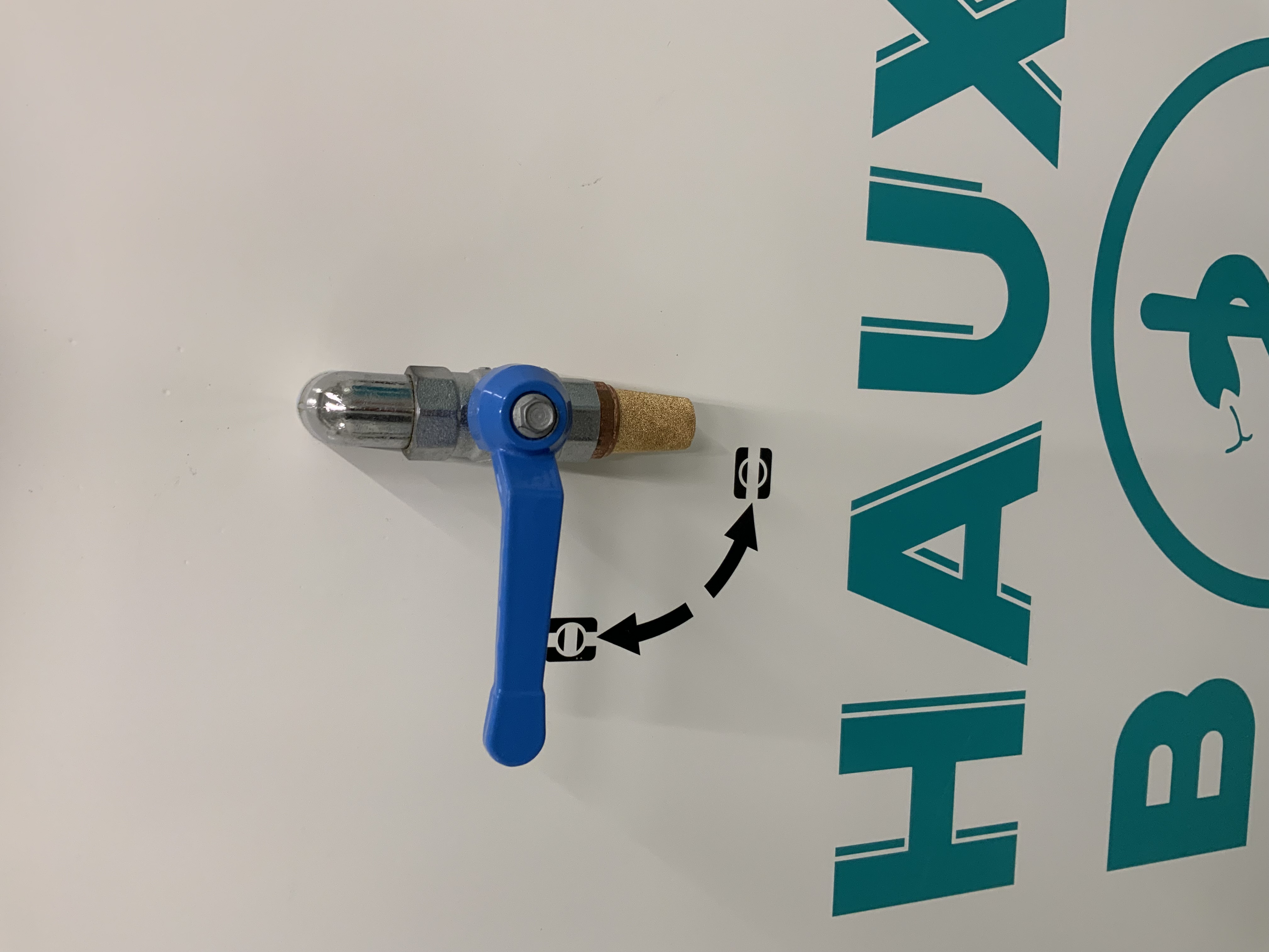
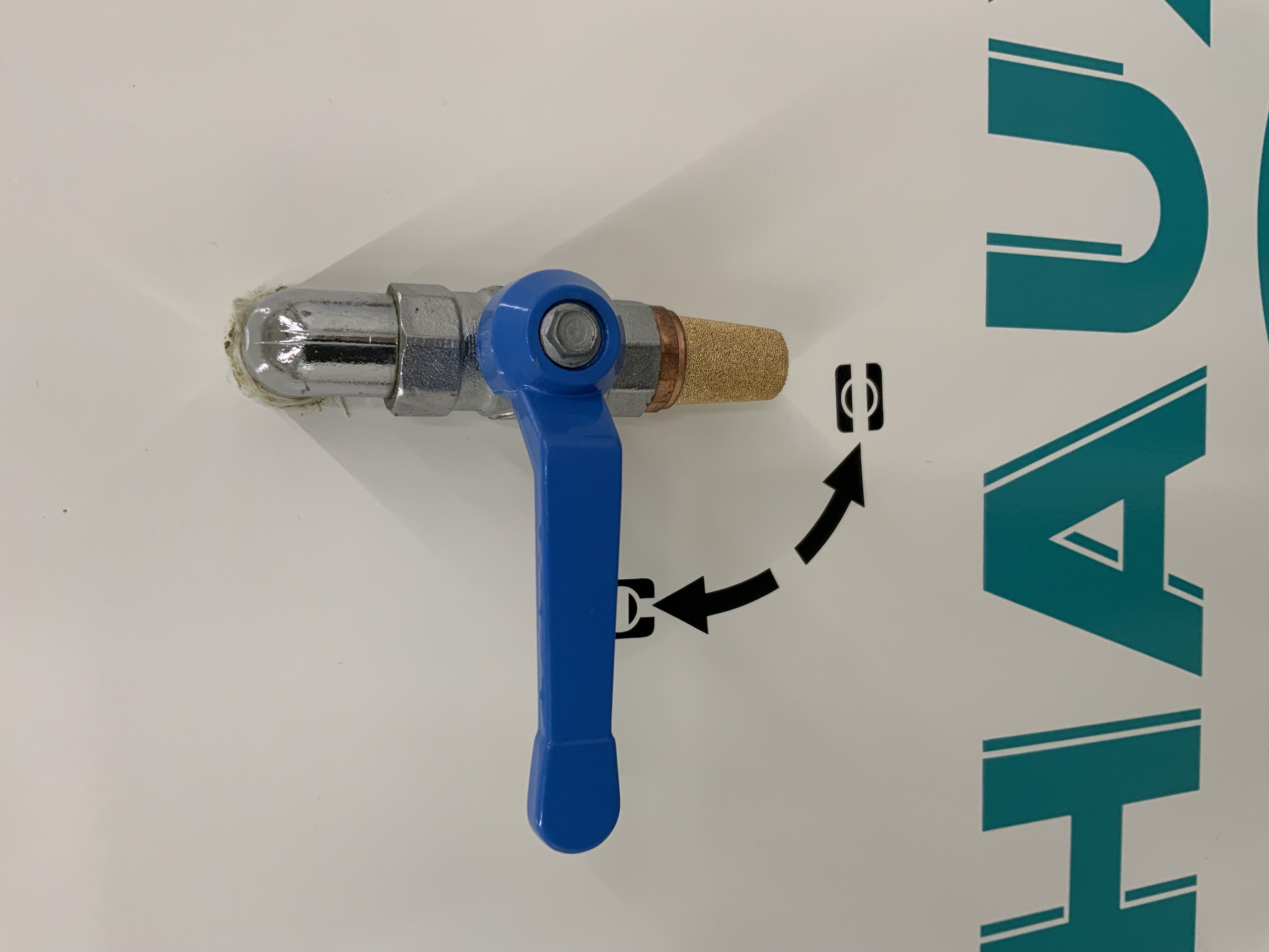
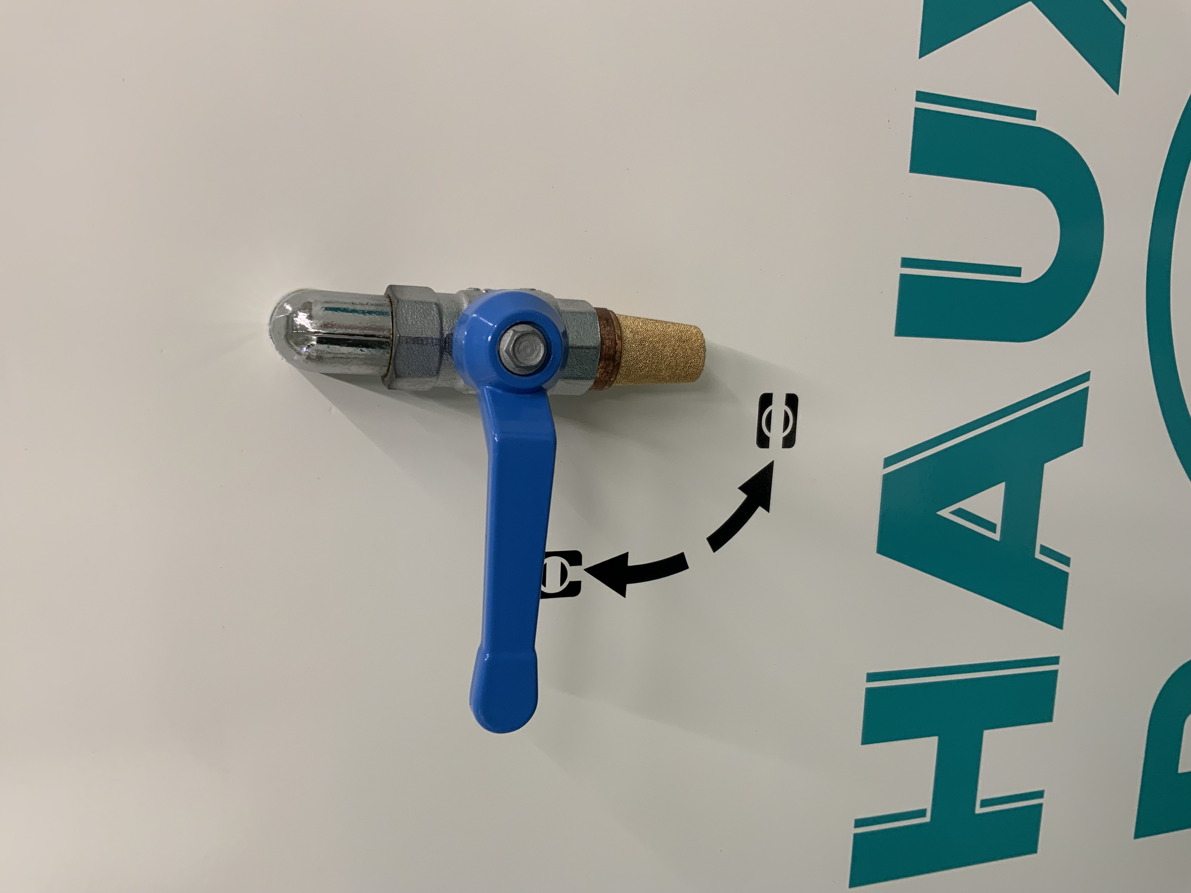
CH 1 : Decomat désactivé & Starvalve fermée
-
-
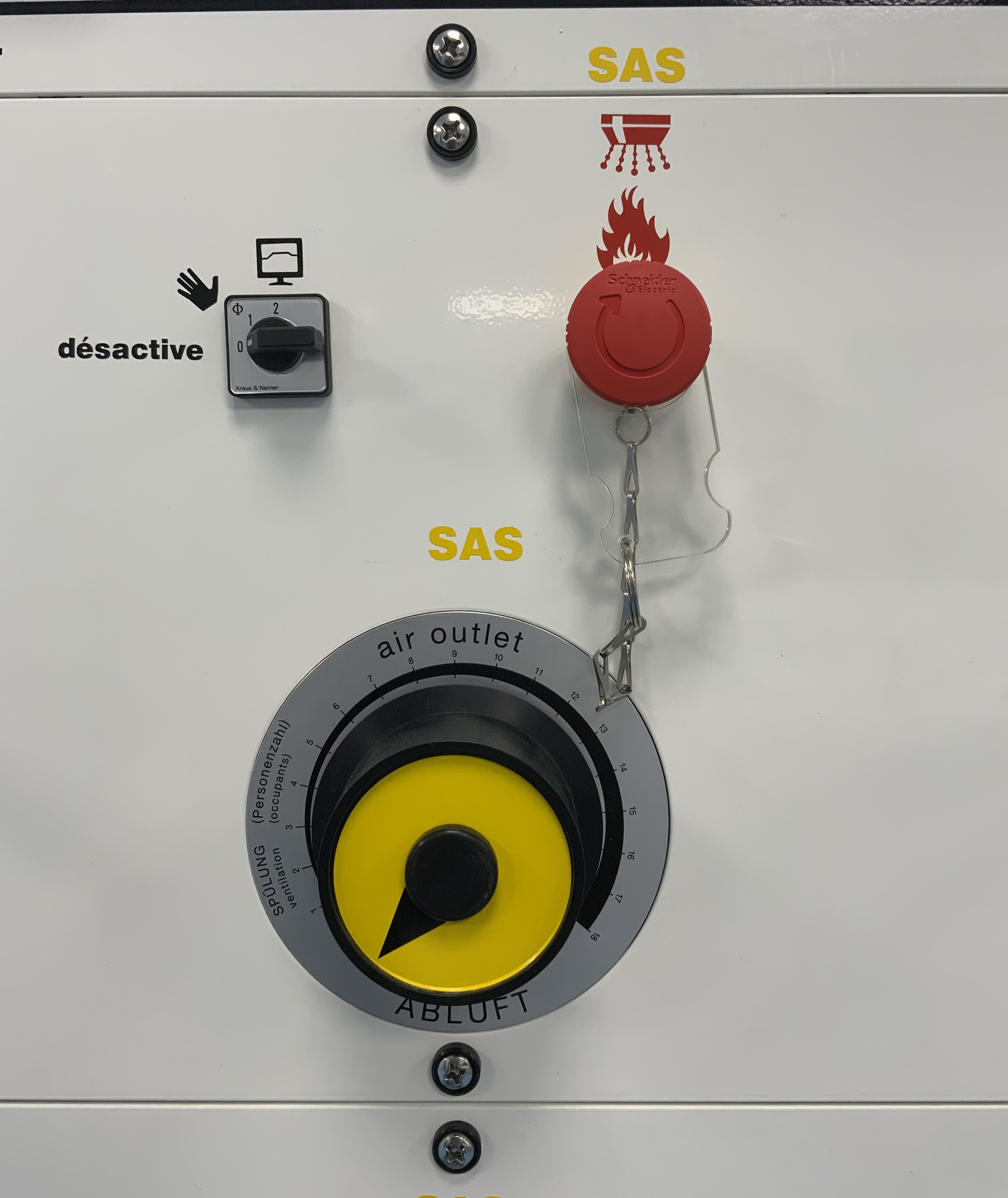
SAS : Ventilation désactivés & Incendie clef et Bouton OK
-
-
CH 2 : Décomat désactivé & Starvalve fermée
-
-
CH 1 : Ventilation désactivés & Incendie Clef et Bouton OK
-
-
SAS : Décomat désactivé & Starvalve au milieu
-
-
CH 2 : Ventilation désactivés & Incendie Clef et Bouton OK
-
-
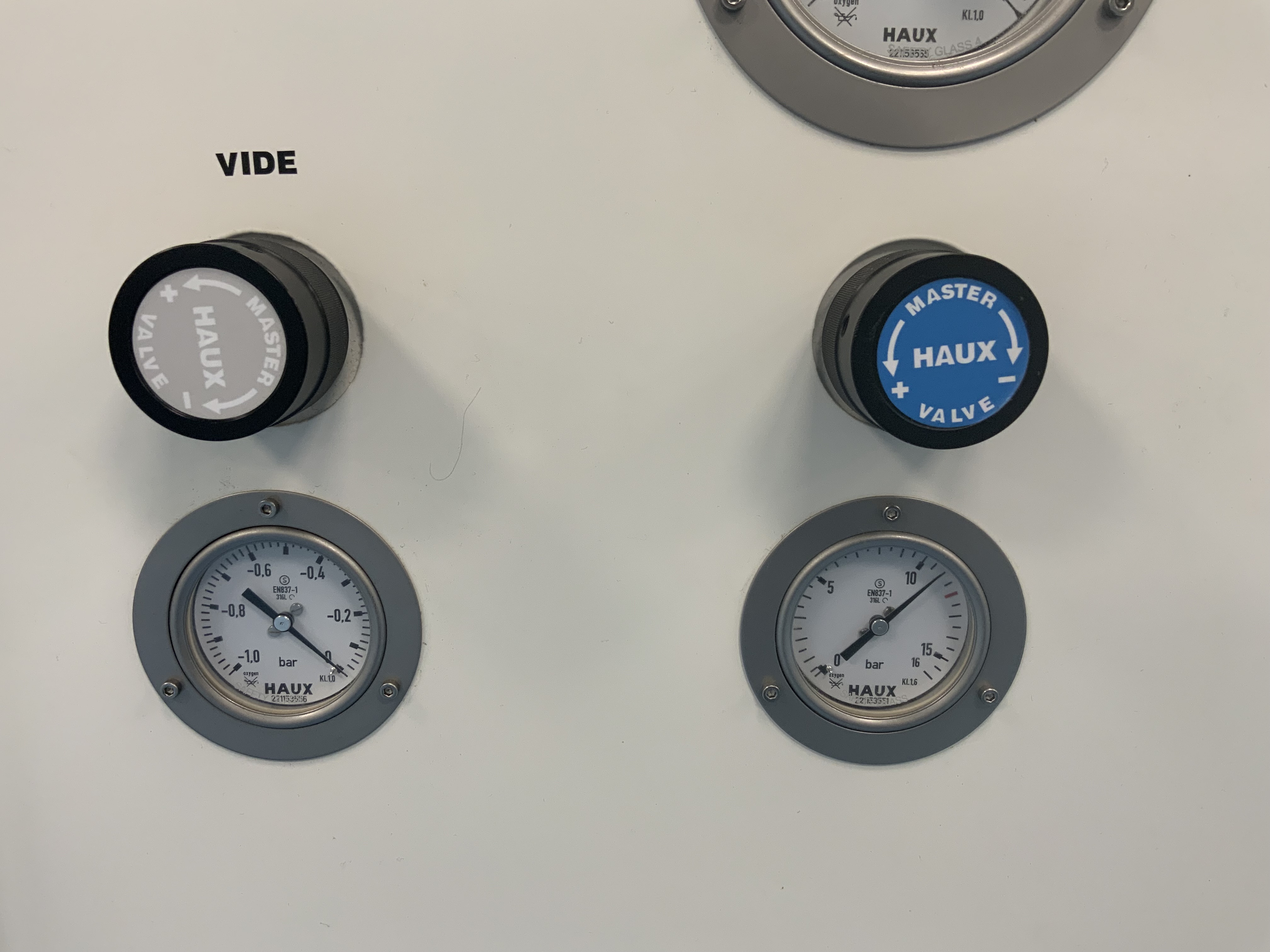
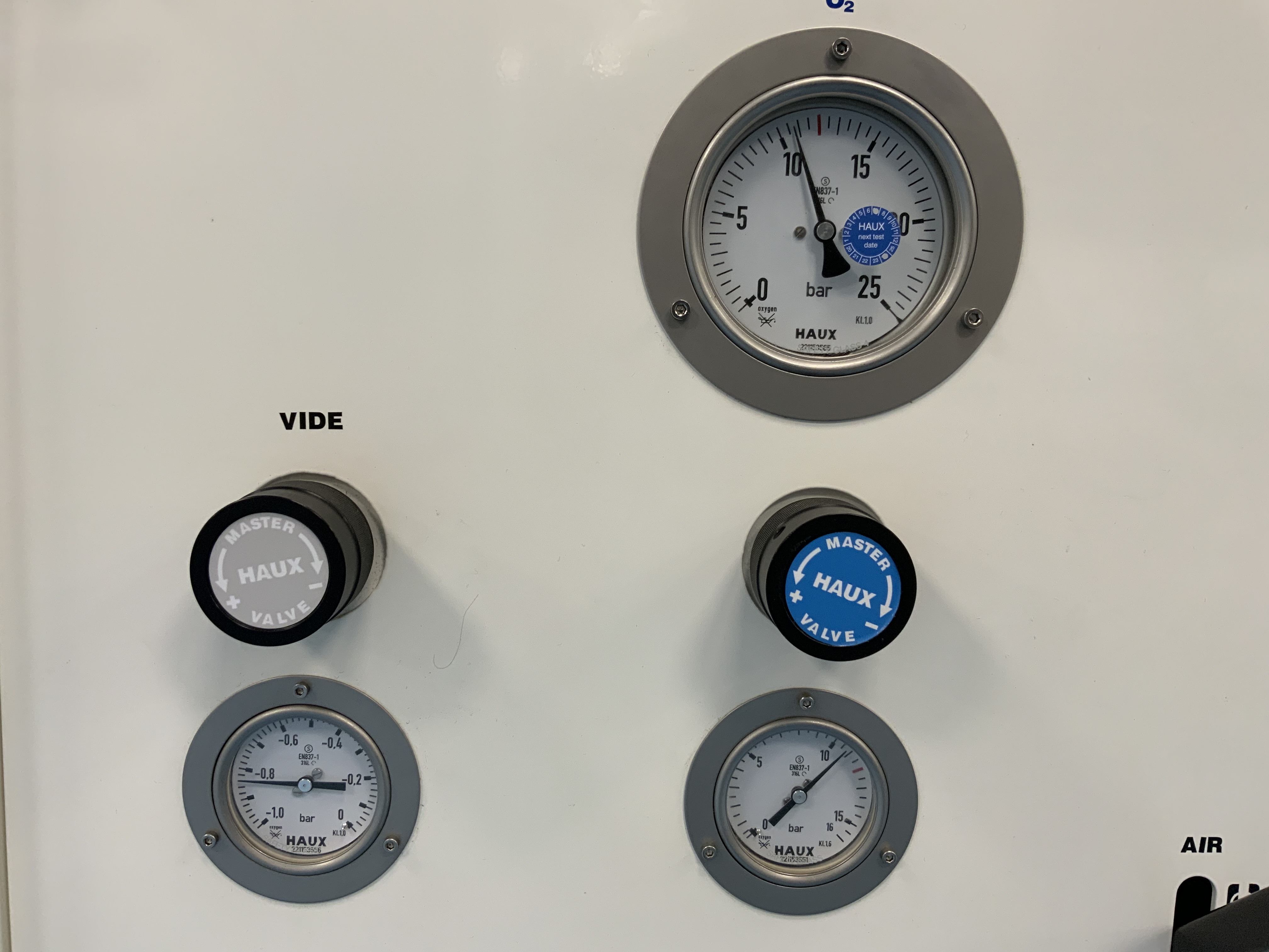
MasterValve VIDE & 02 FERMÉES
-
-
Master Valve AIR & MELANGE FERMEES
-
-
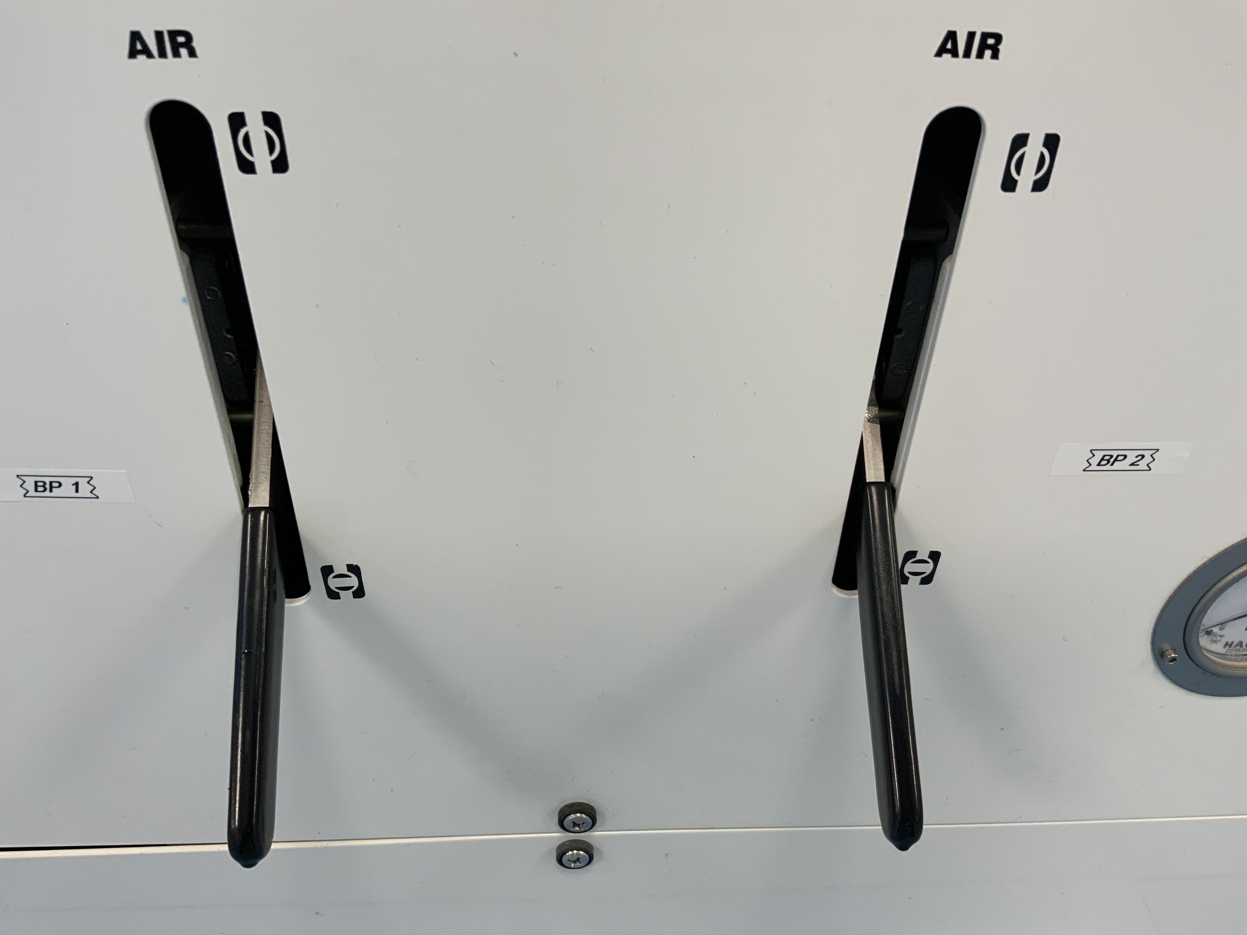
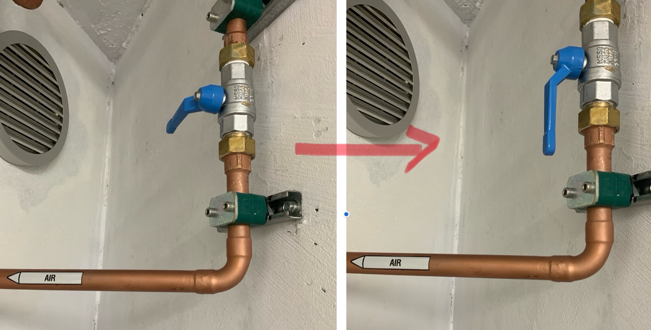
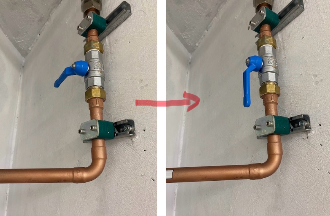
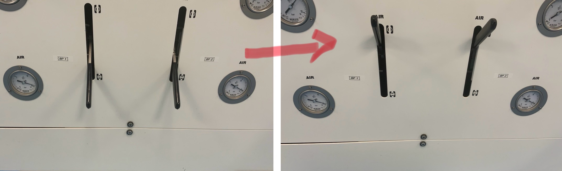
Vanne AIR BP1 BP2 FERMÉES
-


LOCAL TECHNIQUE
-
-
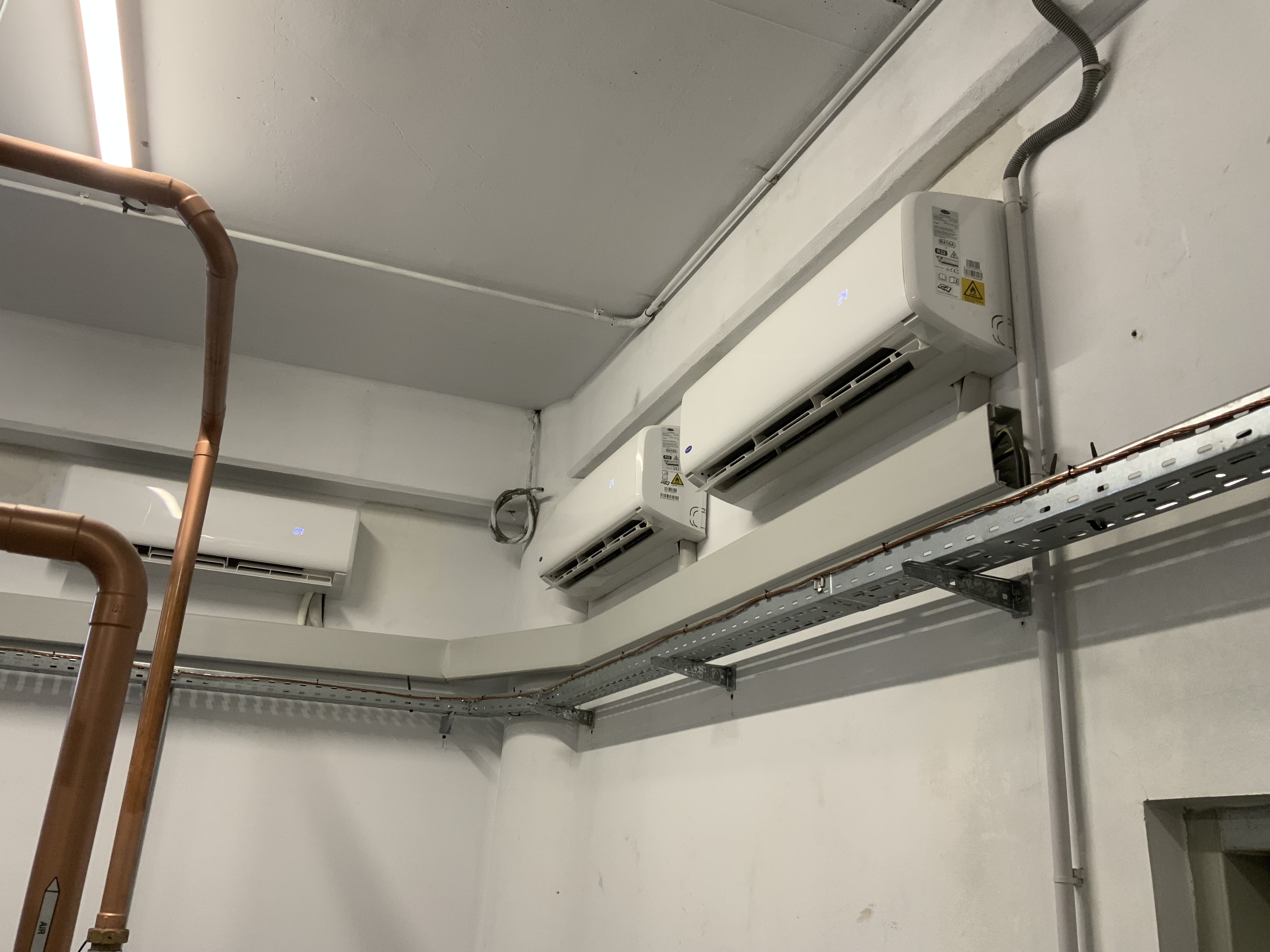
Climatisation en marche x4
-
-
Voyant électrique OK
-
-
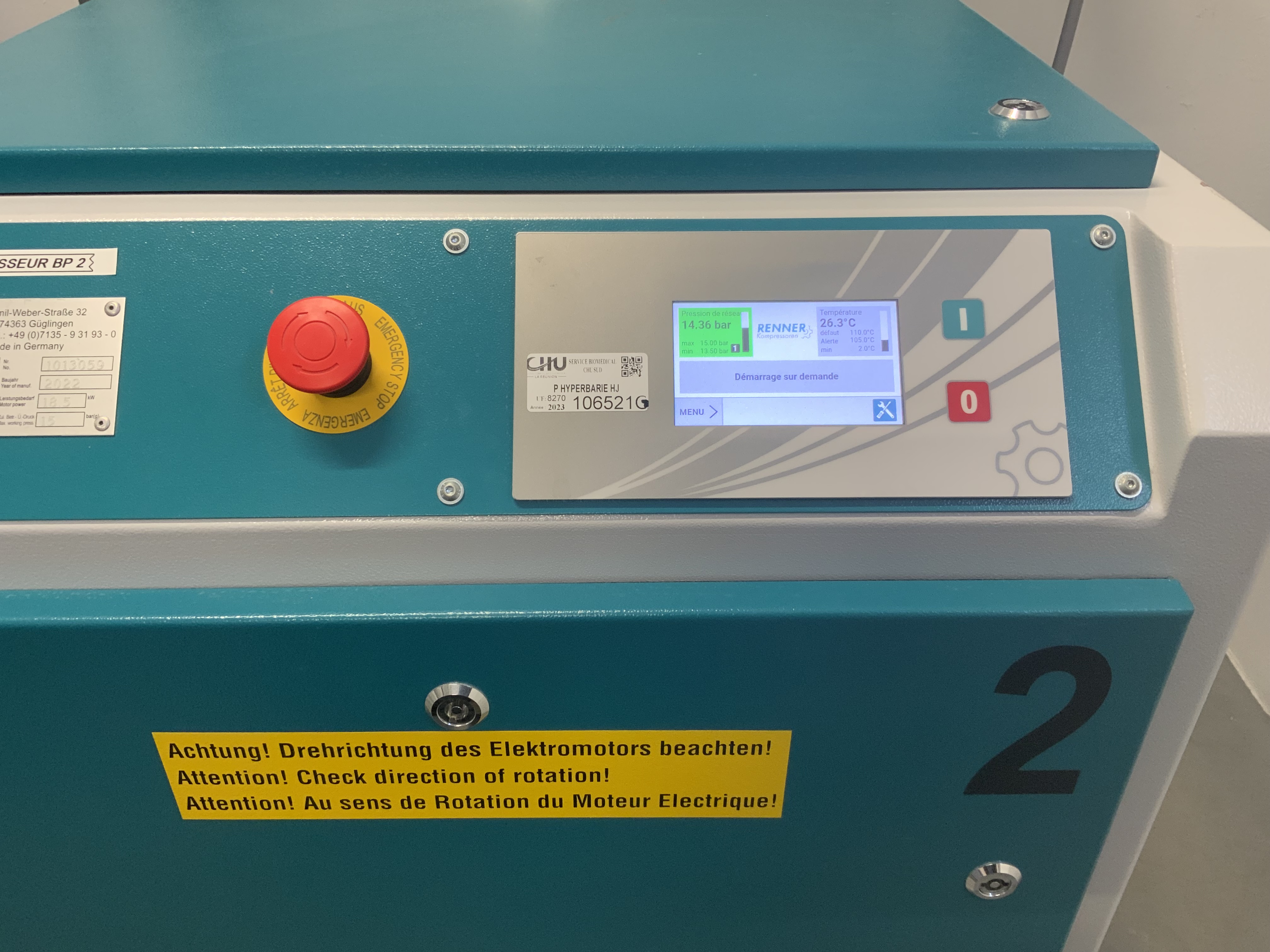
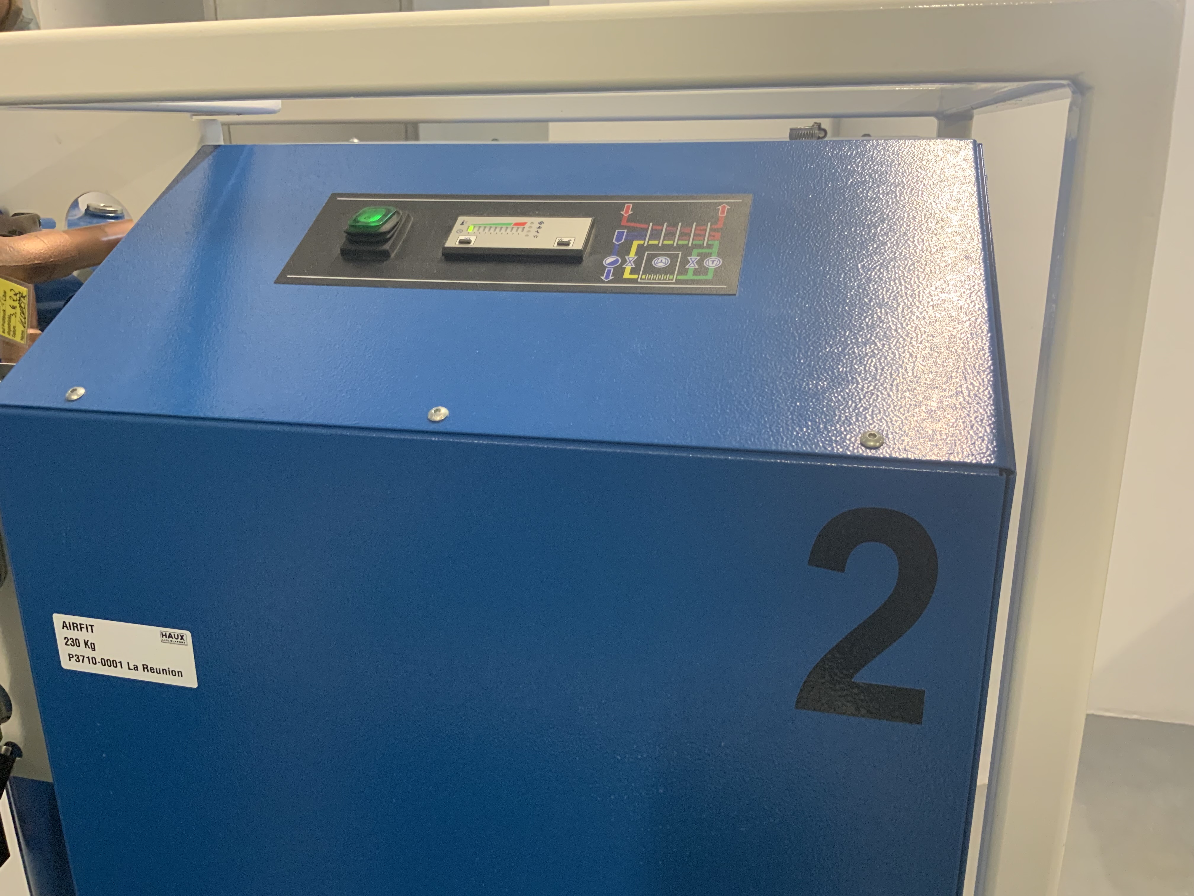
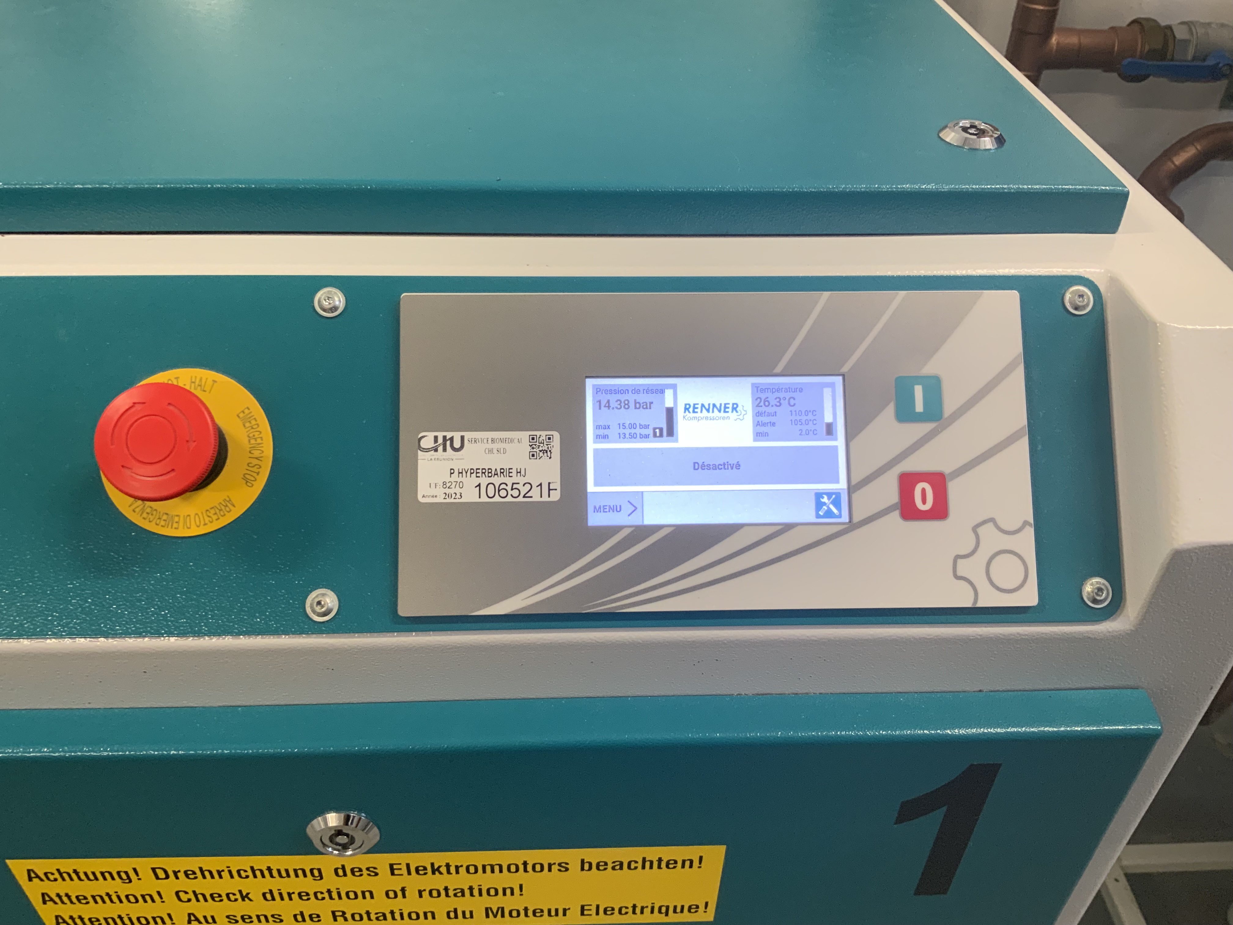
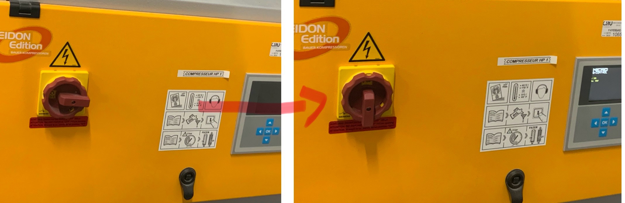
Compresseur 2 : Allumé
-
-
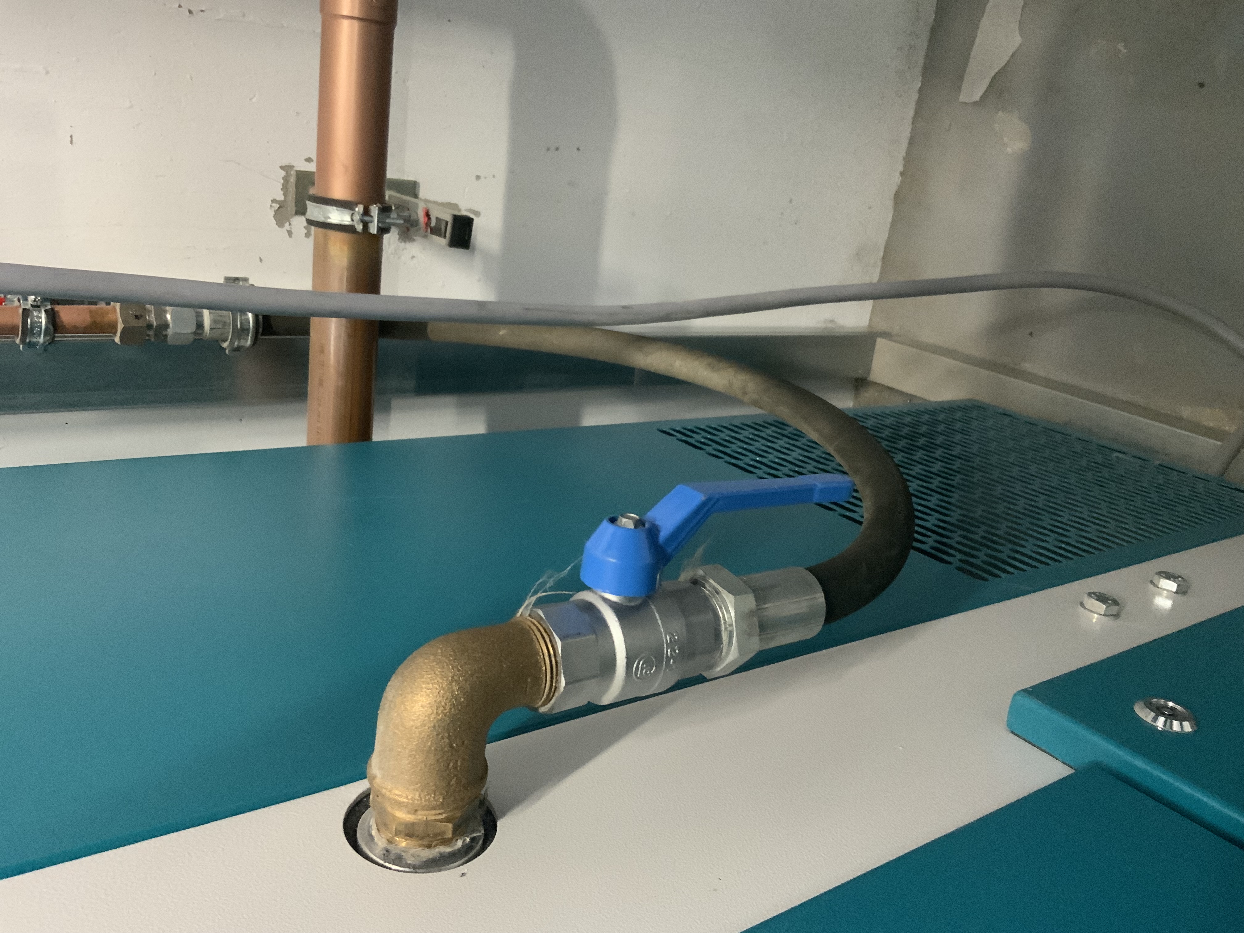
Compresseur 2 : Vanne ouverte
-
-
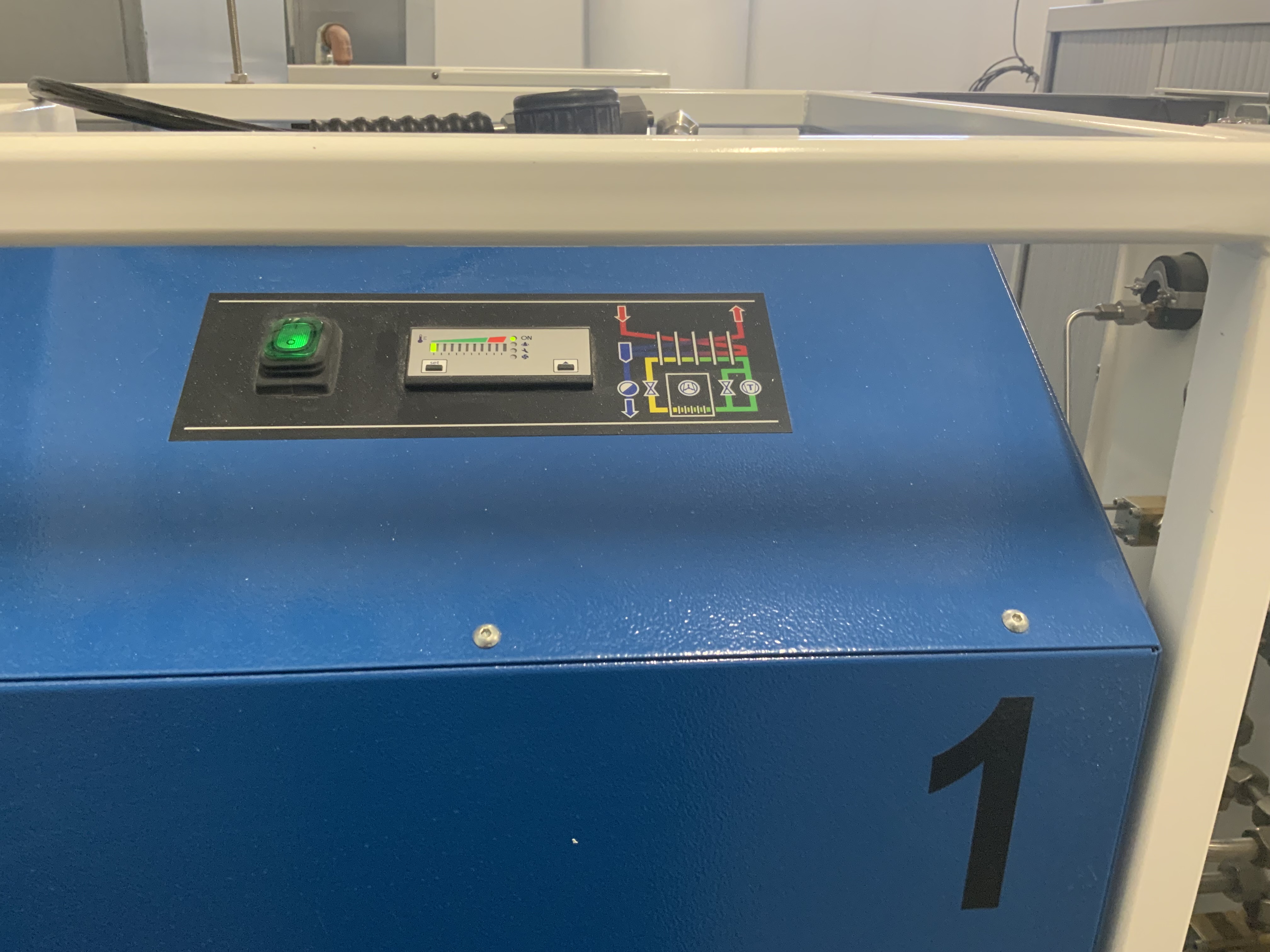
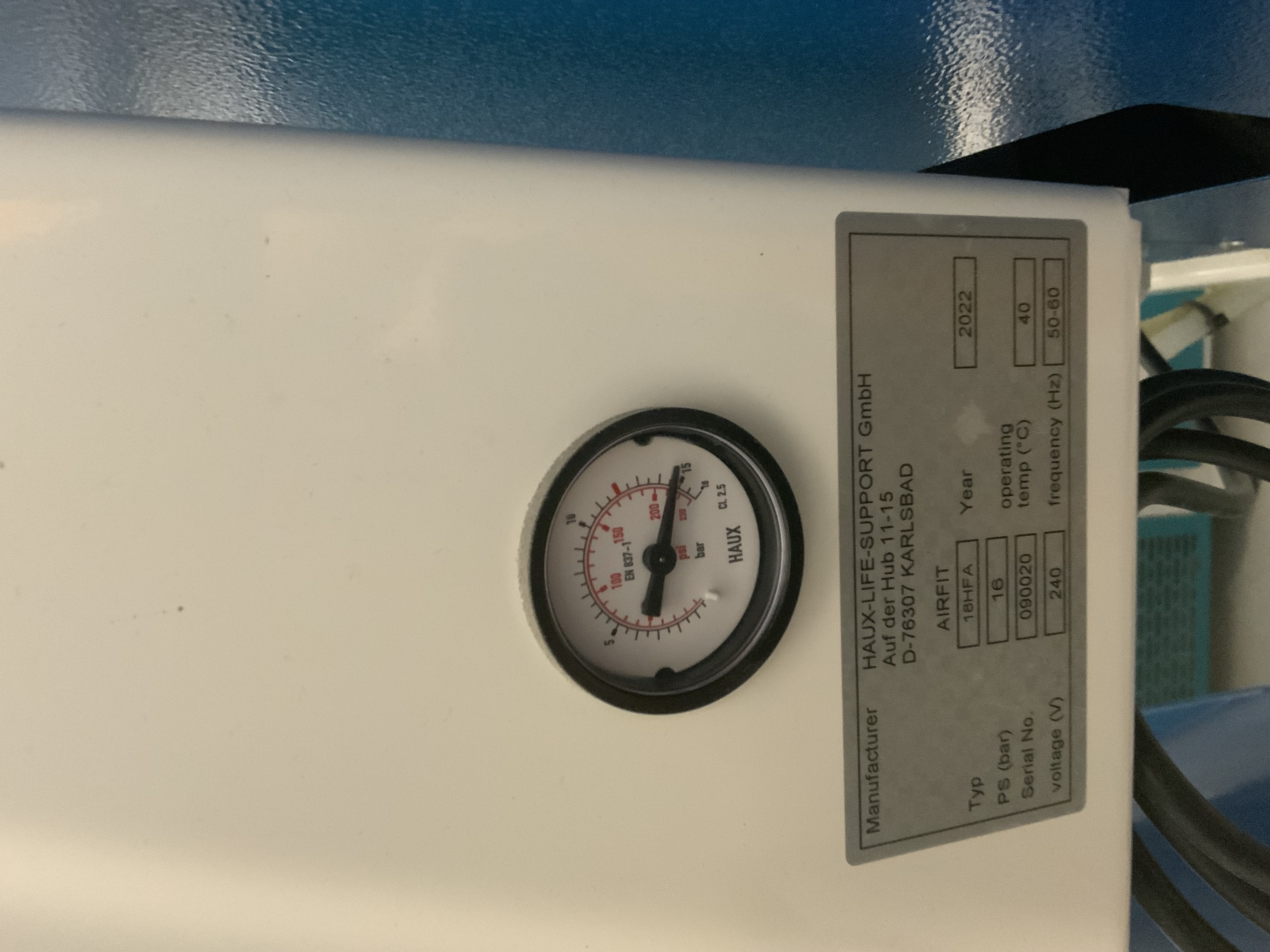
Airfit 2 : Voyant sur vert
-
-
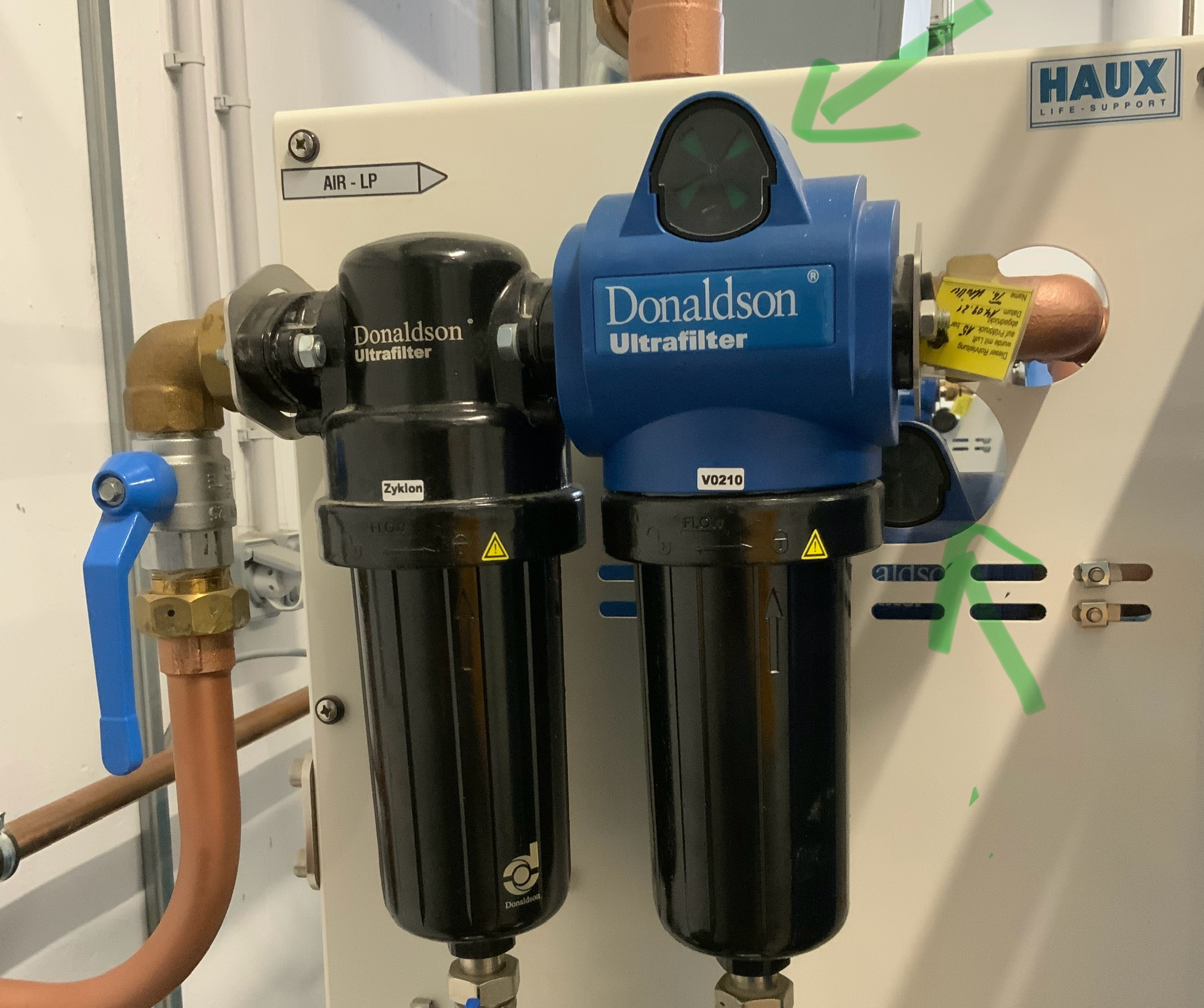
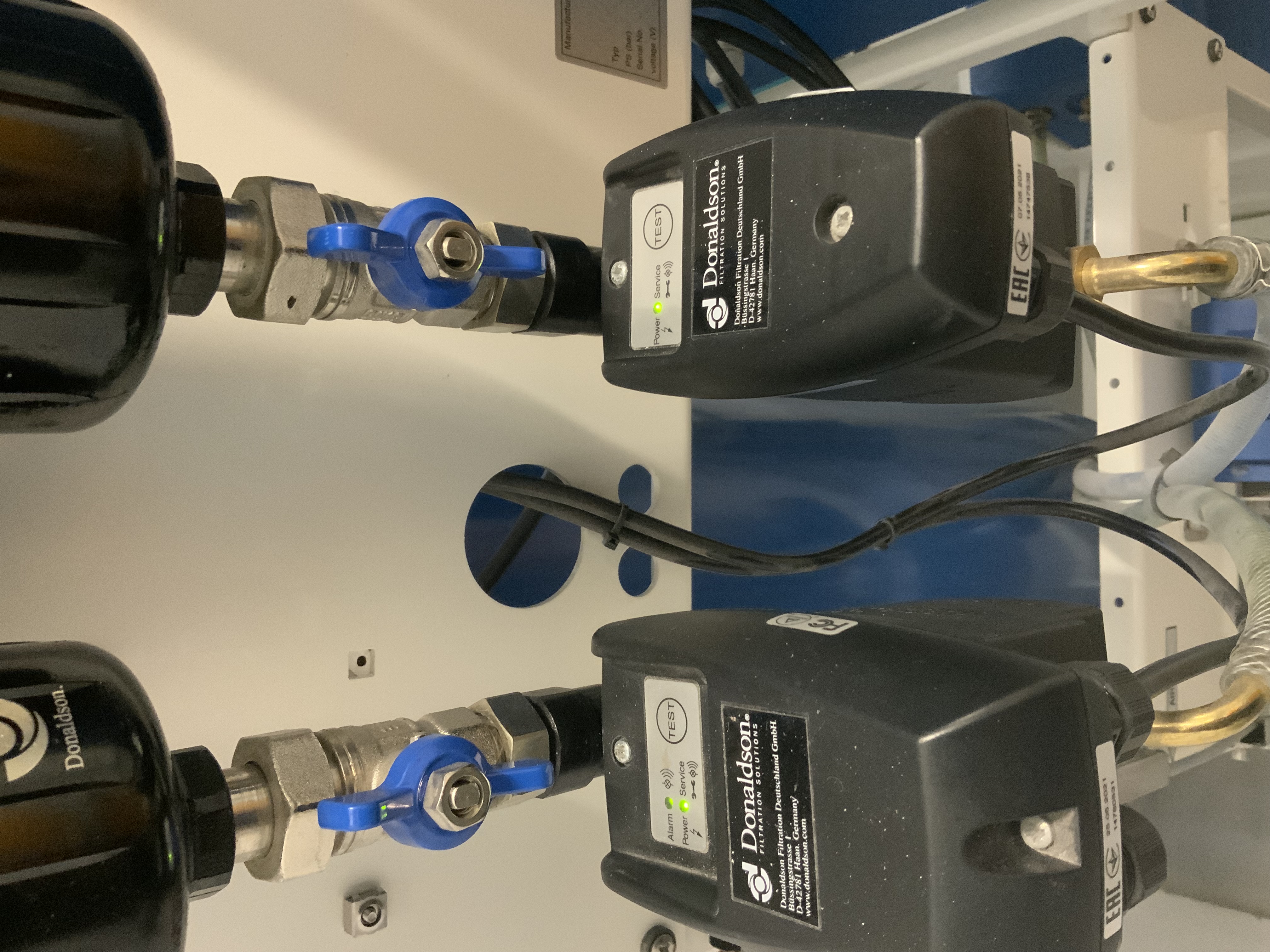
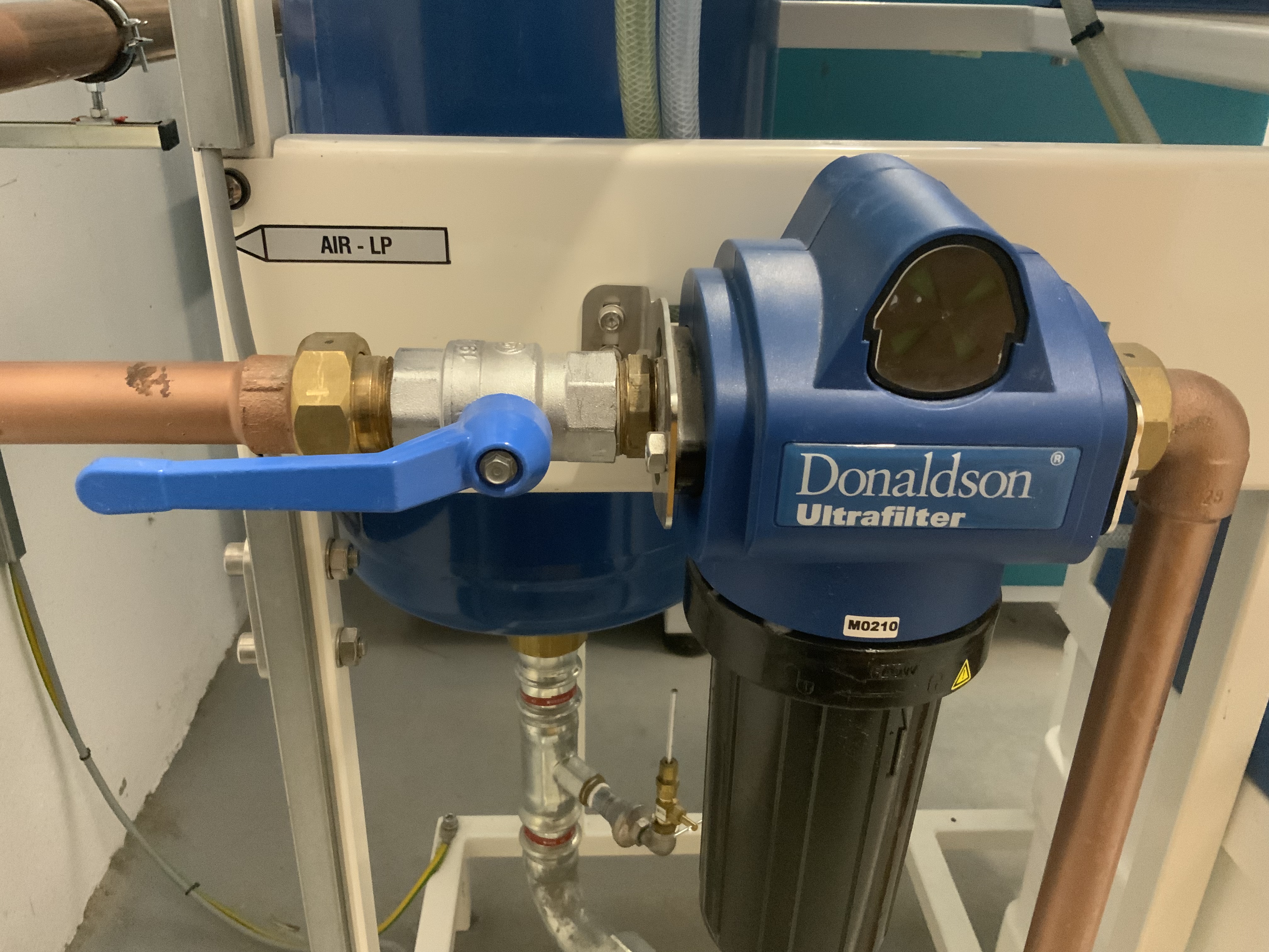
Airfit 2 : Vanne d’arrivée ouvert & filtres x2 Vert
-
-
Airfit 2 : Vannes ouvertes et test 1&2 OK
-
-
Airfit 2 : Test 3 OK
-
-
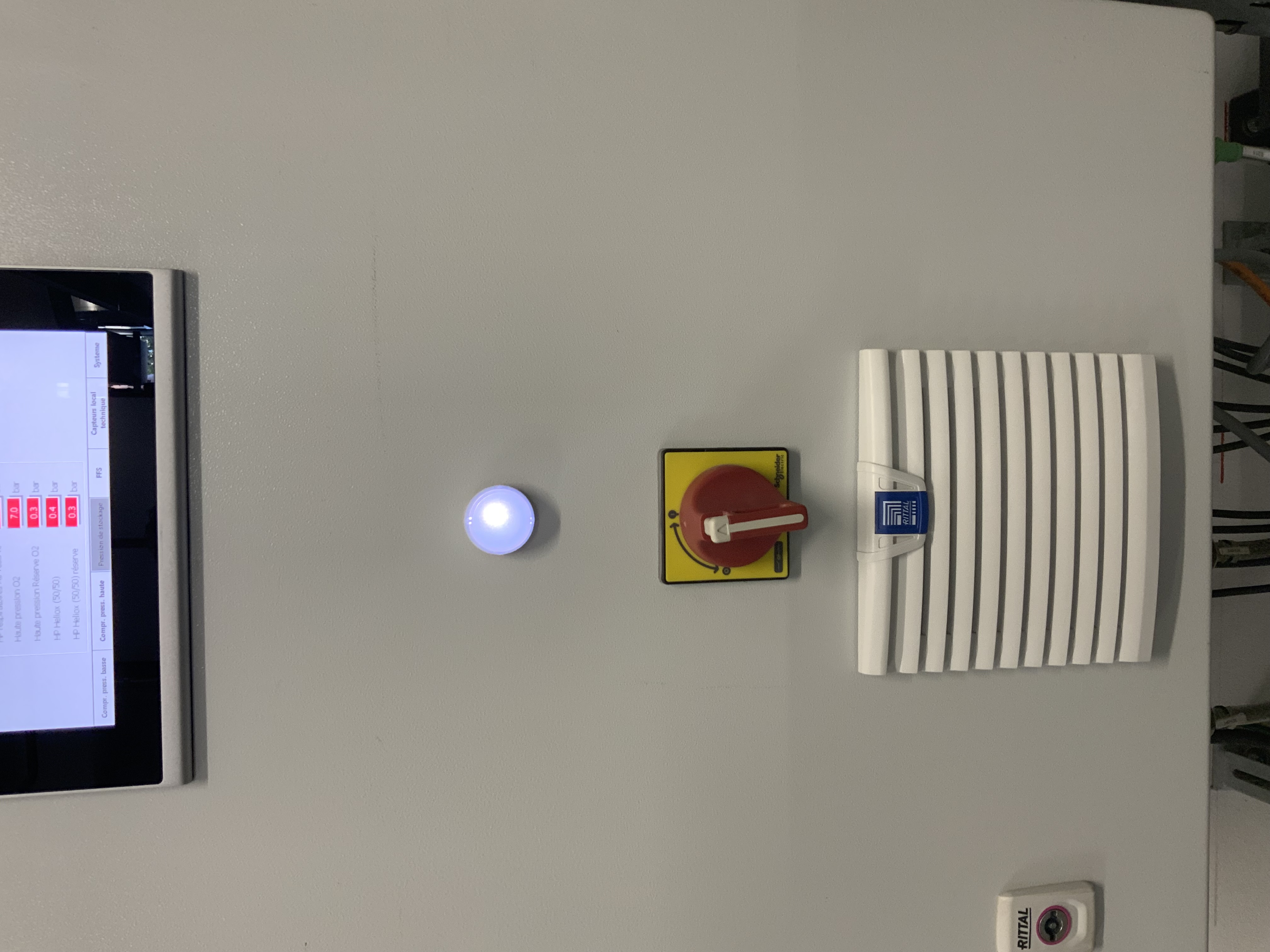
Pression 7-15b
-
-
Airfit 2 : Vanne de sortie ouverte & filtre sur Vert
-
-
BY-PASS AIRFIT ouvert
-
-
BY-PASS Compresseur : Fermé
-
-
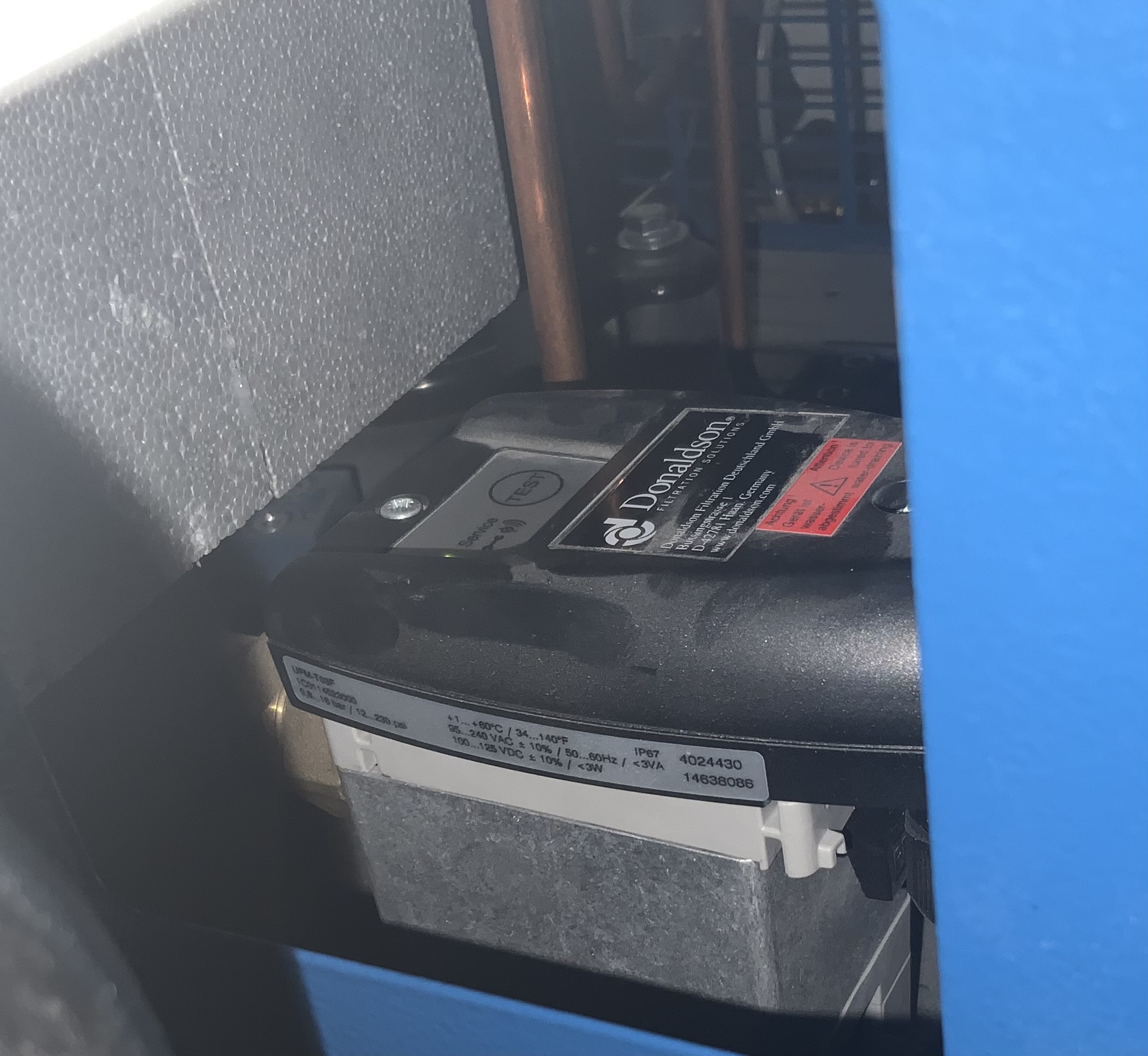
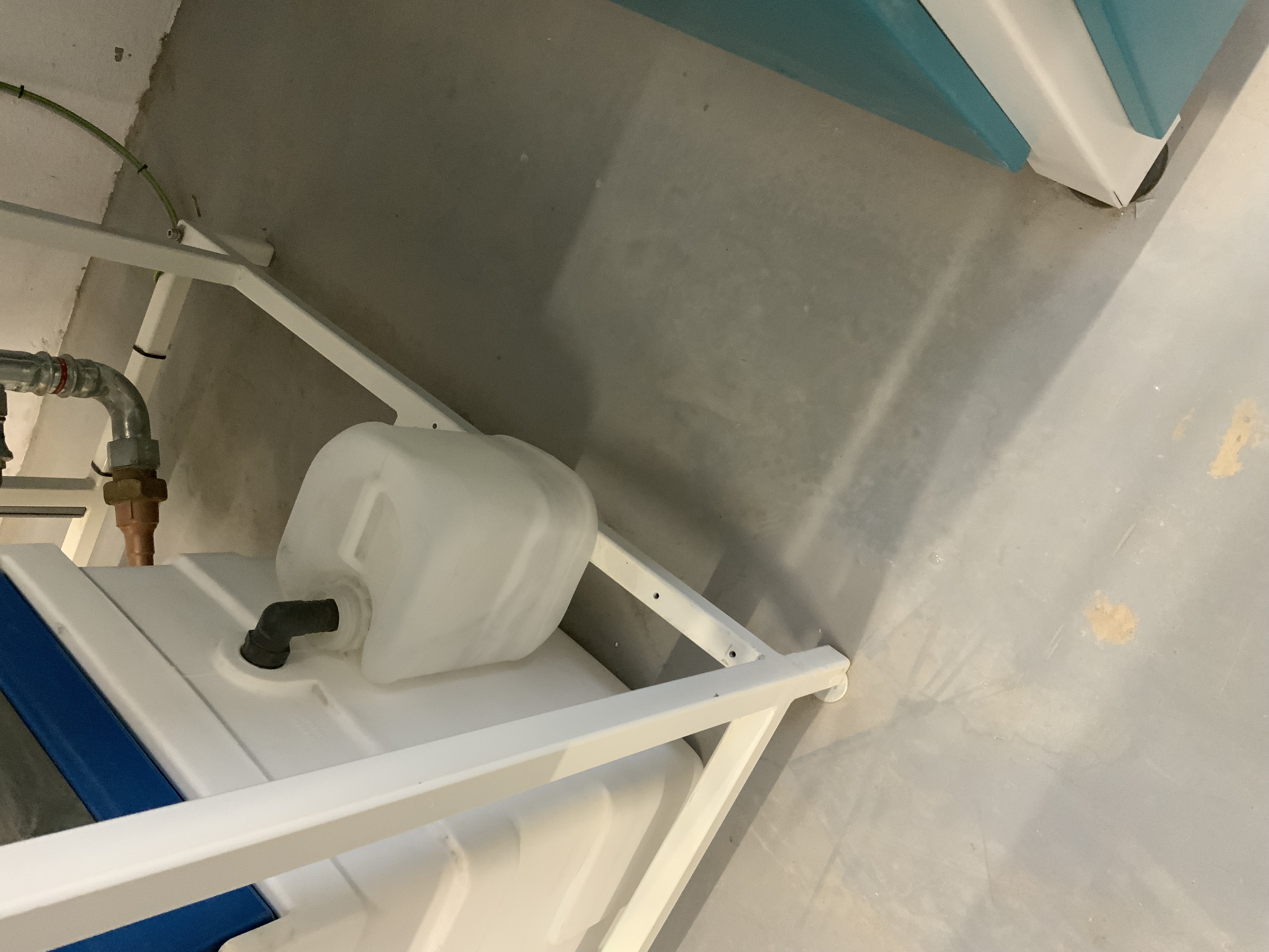
Airfit 2 : Condensat OK
-
-
Compresseur 1 : Vanne ouverte
-
-
Compresseur 1 : Allumé
-
-
Airfit 1 : voyant sur vert
-
-
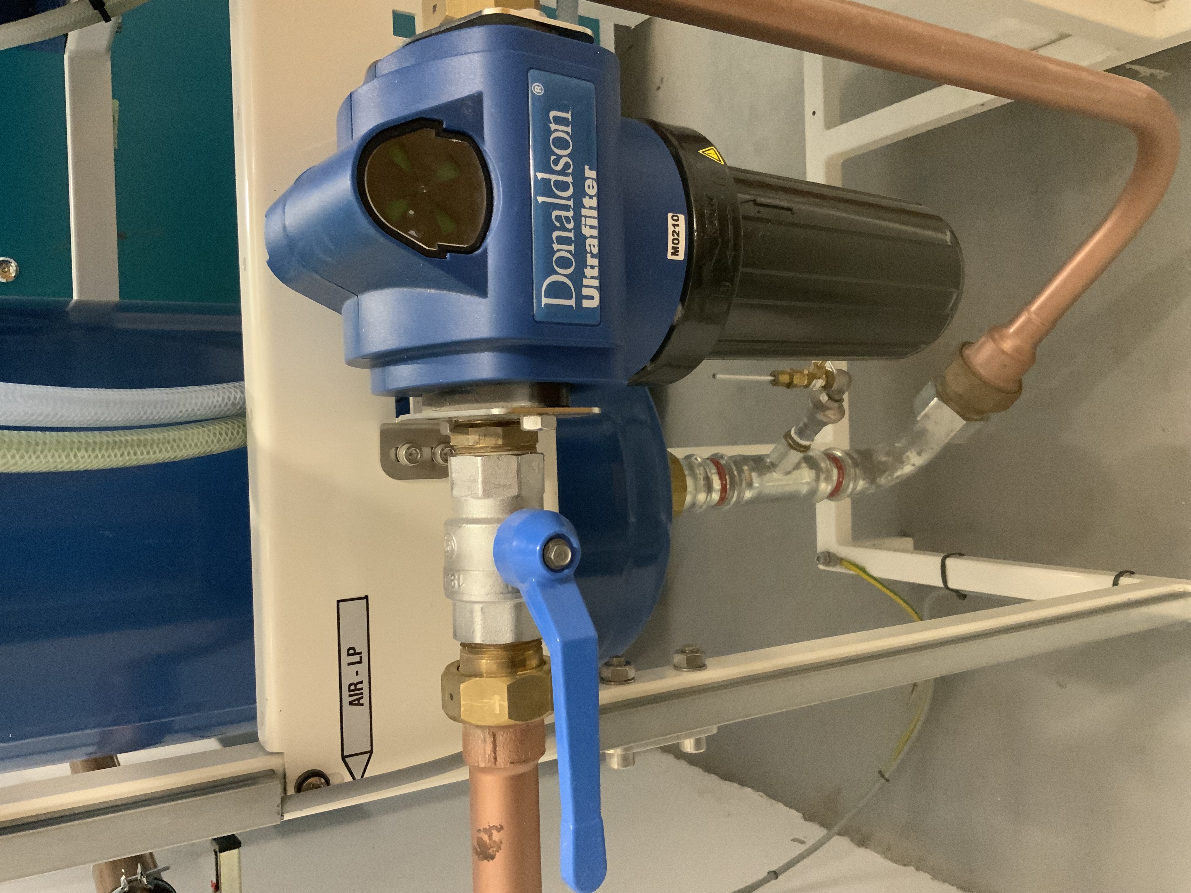
Air fit 1 : Vanne d’arrivée ouverte & filtre sur vert
-
-
Airfit 1 : vannes ouvertes & test x2 OK
-
-
Airfit 1 : Test 3 OK
-
-
Pression 7-15b
-
-
Airfit 1 : Vanne sortie ouverte & contrôle du filtre vert
-
-
Condensat vide
-
-
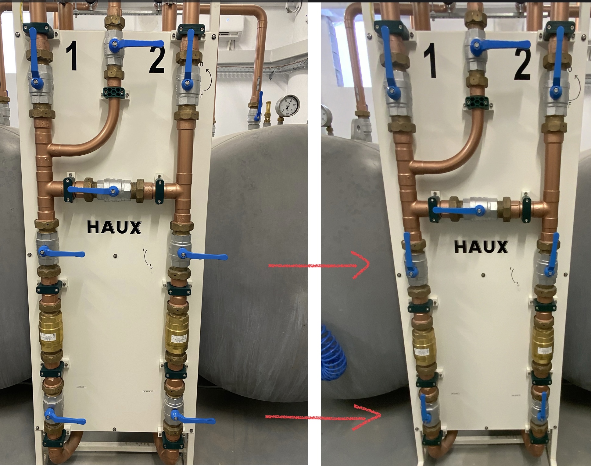
BP : Vannes de remplissage ouvertes
-
-
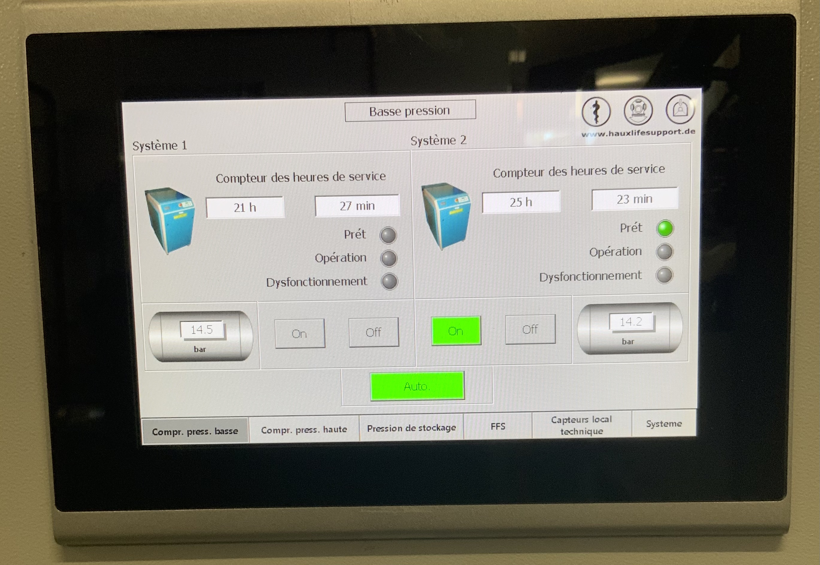
BP 1 : Manomètre : 12-14b
-
-
BP 2 : Manomètre : 12-14b
-
-
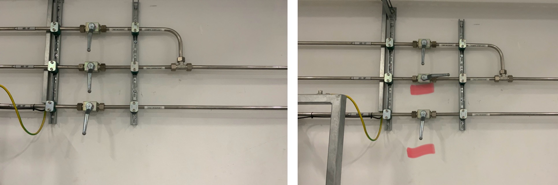
Distributeur BP : ouvrir les vannes
-
-
HP ouverture : Allumé
-
-
HP : Condensat OK
-
-
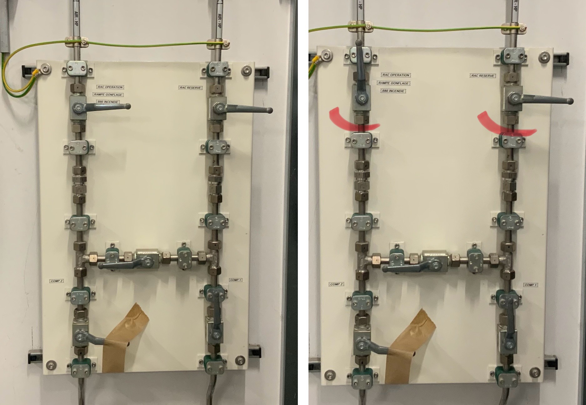
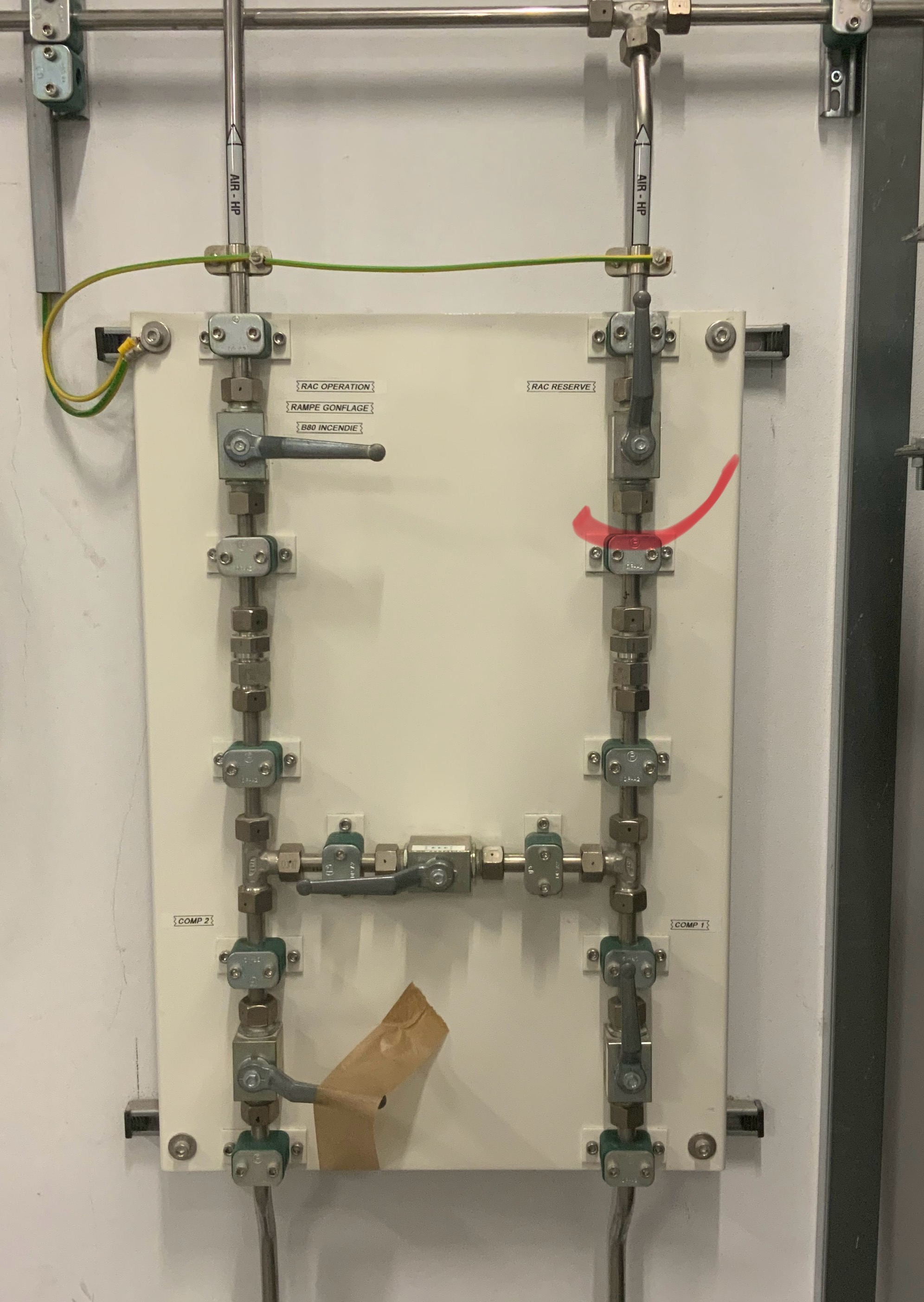
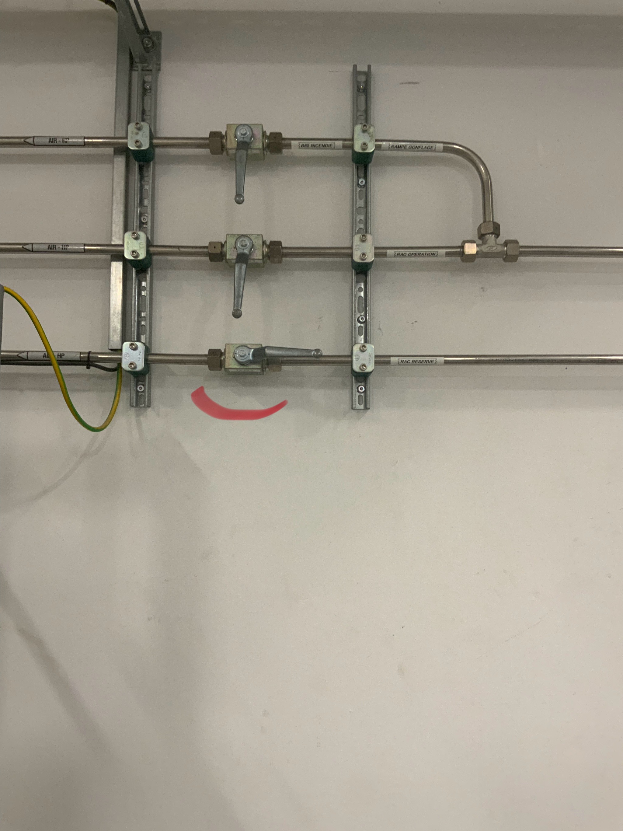
HP : vanne RAC Opération : ouverte (choisir le RAC à ouvrir)
-
-
HP : Vanne de la ligne au RAC Opération : ouverte
-
-
HP : Vanne RAC Réserve :ouverte (choisir le RAC à ouvrir)
-
-
HP : Vanne de la ligne au RAC Réserve : ouverte
-
-
HP : tableau détente ouvert
-
-
HP : Vanne vers la BP : ouverte
-
-
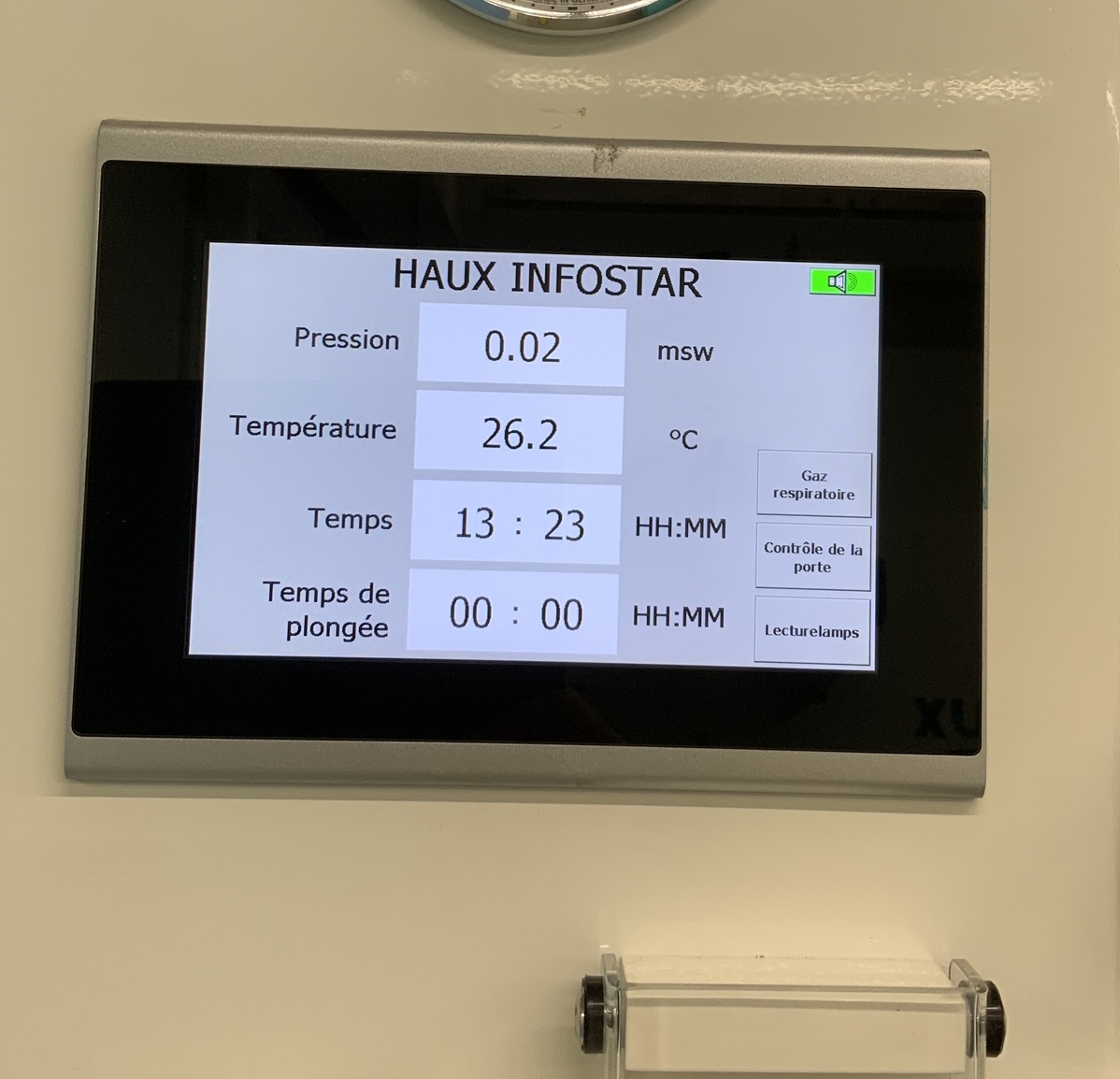
BUS : mode automatique
-
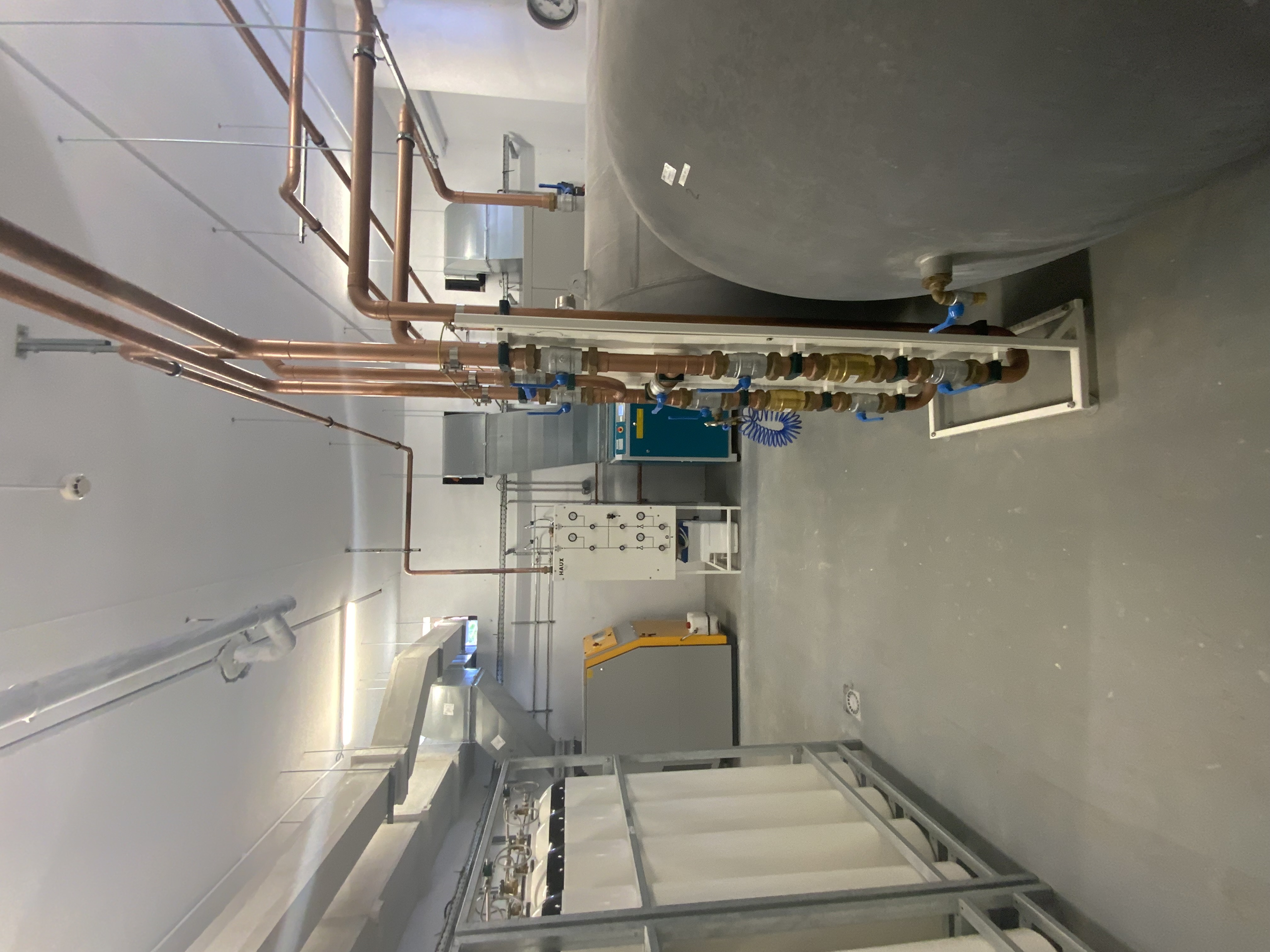


LOCAL TECHNIQUE FLUIDE MÉDICAUX
-
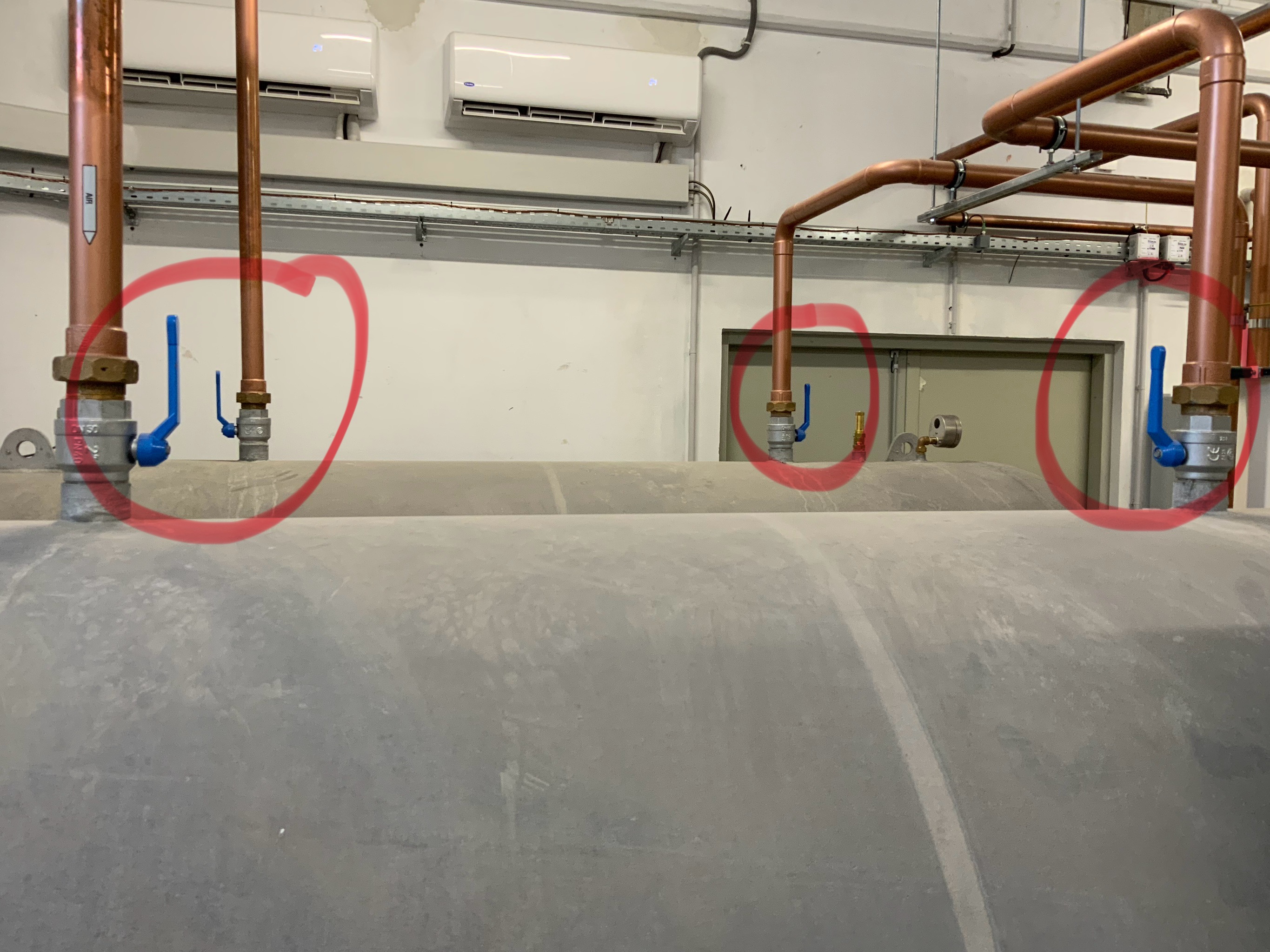
Vanne alimentation AIR : Ouverte
-
-
Pression AIR : 10-12bars
-
-
Vanne alimentation O2 : ouverte
-
-
Pression O2 : 10-12 bars
-

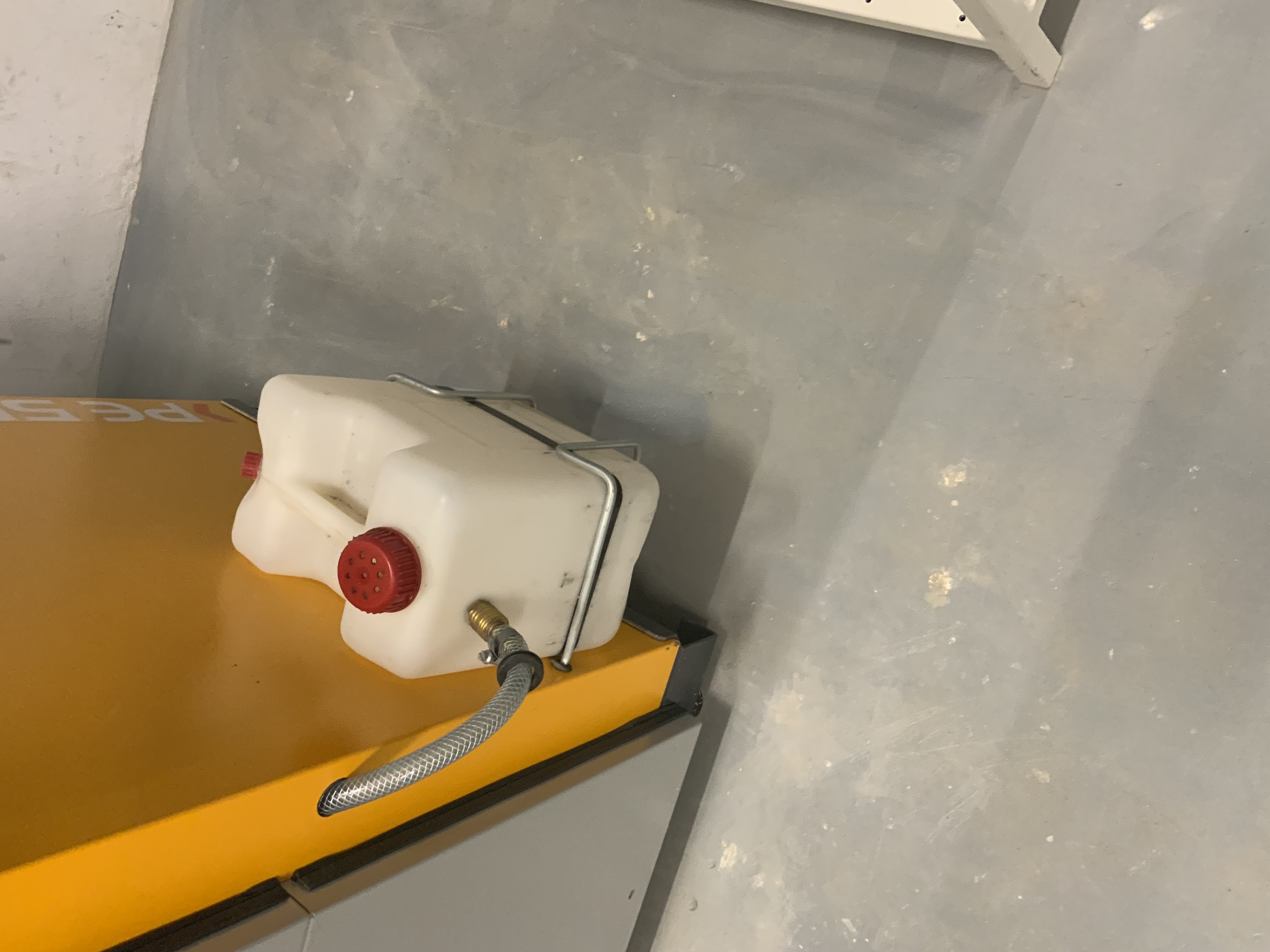
LOCAL TECHNIQUE CUVE INCENDIE
-
Vanne remplissage B80 : Fermée
-
-
B80 : Robinets Ouverts et plombées & purge fermée
-
-
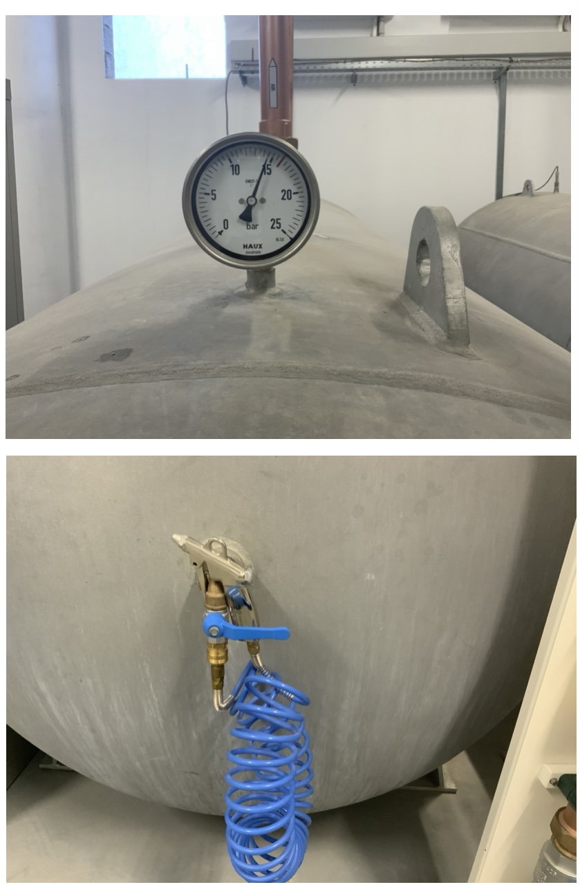
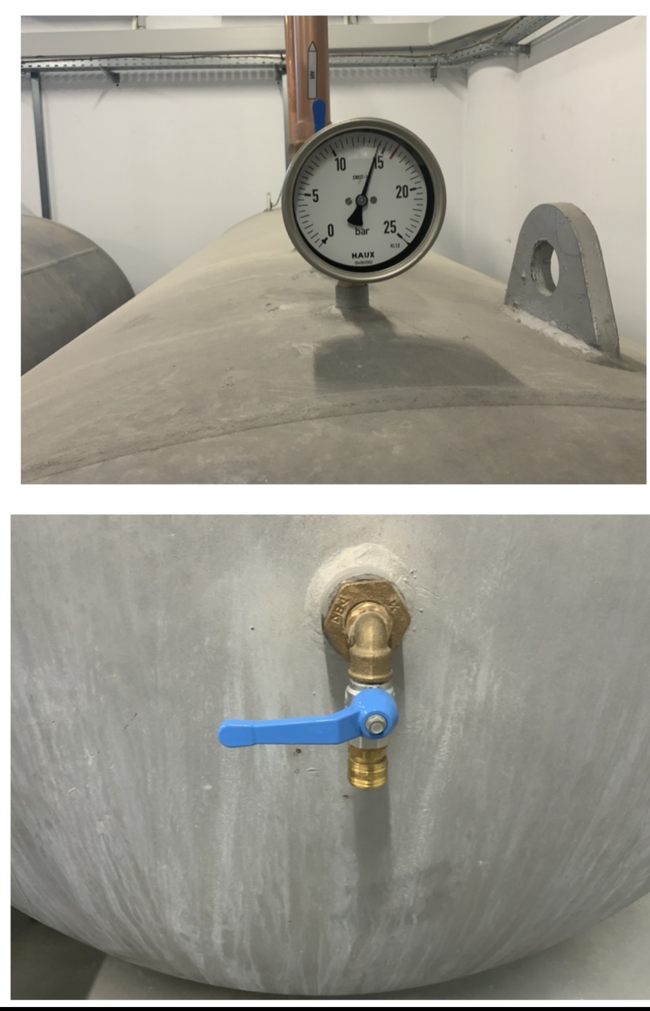
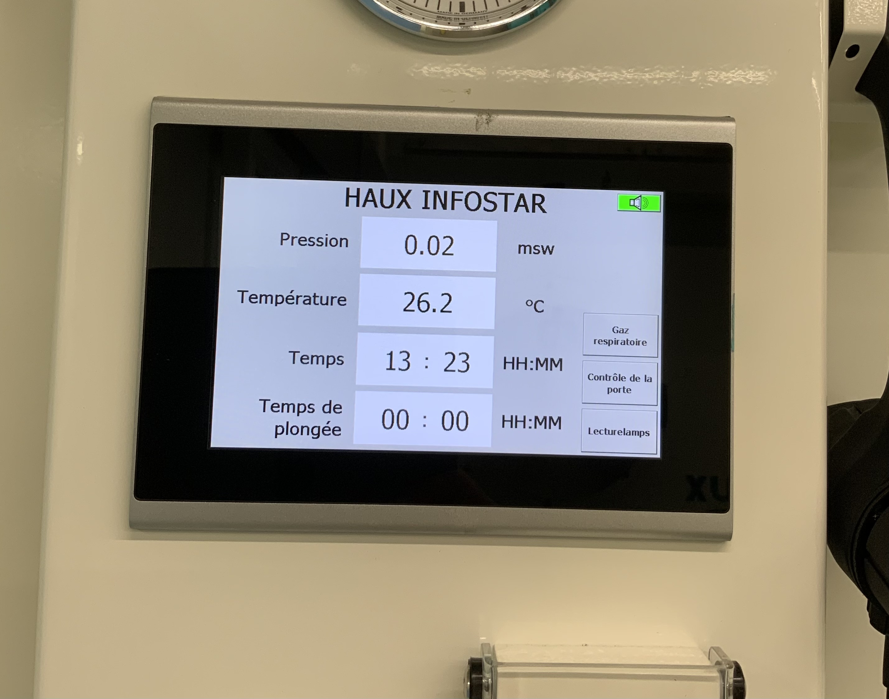
Manomètre : B80 à180-200 bars & Pression Cuve à 28-30 bars
-
-
Manomètre air pilotage : 8 bars
-
-
Cuve : Purge fermée & Vanne alimentation ouverte plombées
-
-
Cuve : Vanne Sortie ouverte & vanne vidange ou remplissage fermée plombées
-
-
Climatisation fonctionnelle
-
-
Climatisation : position IES
-
-
Chauffage à 60°C
-
-
Vanne du système ouverte
-
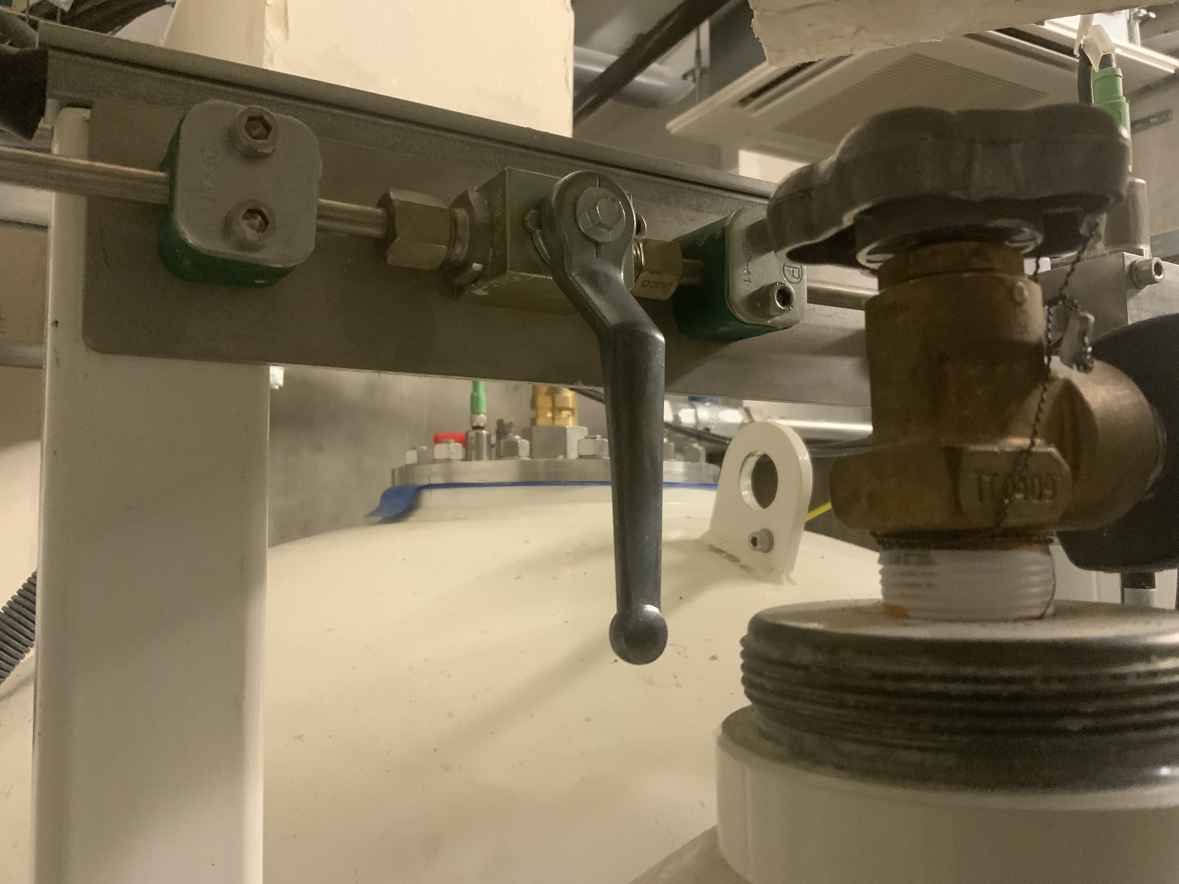
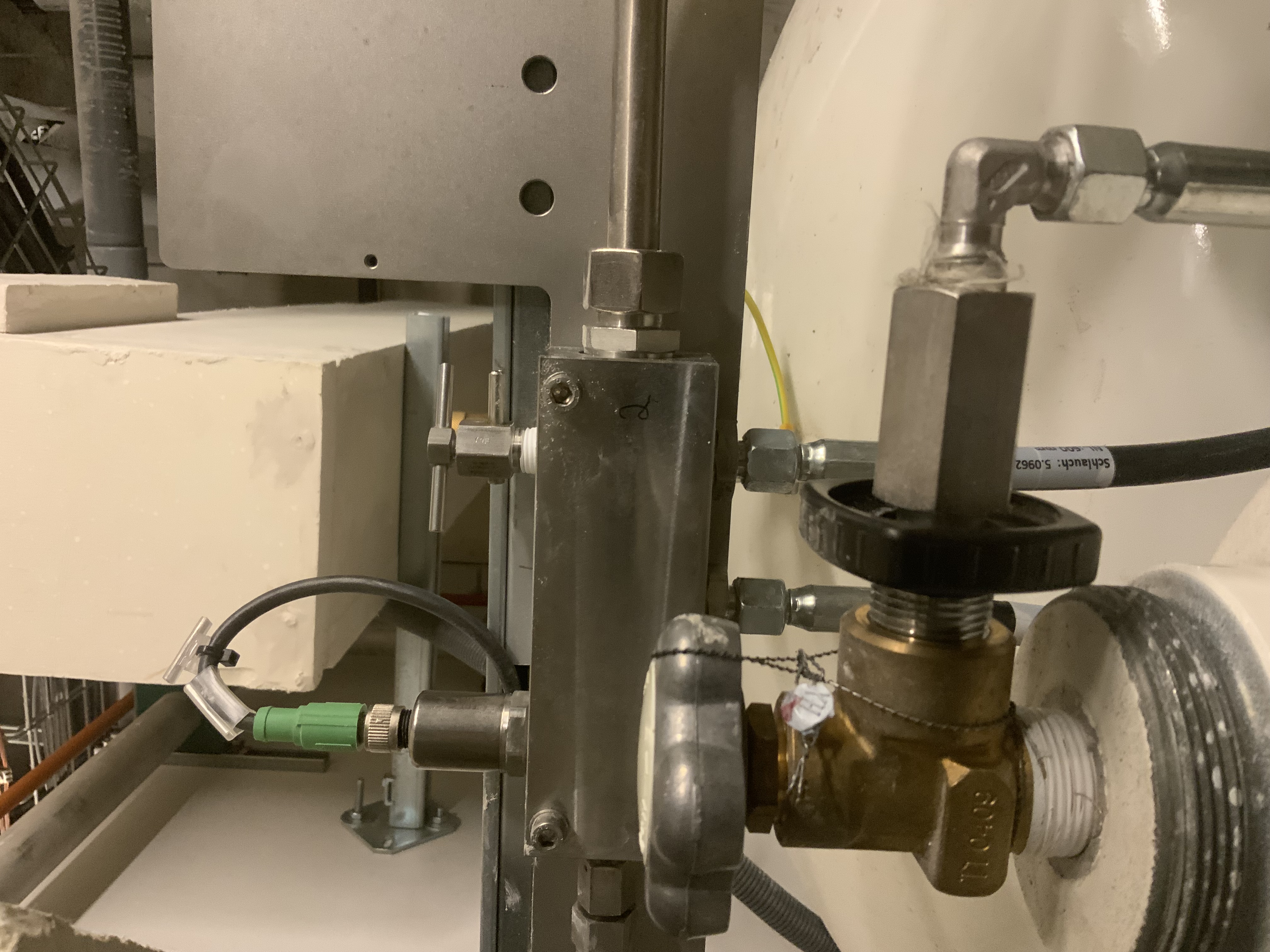
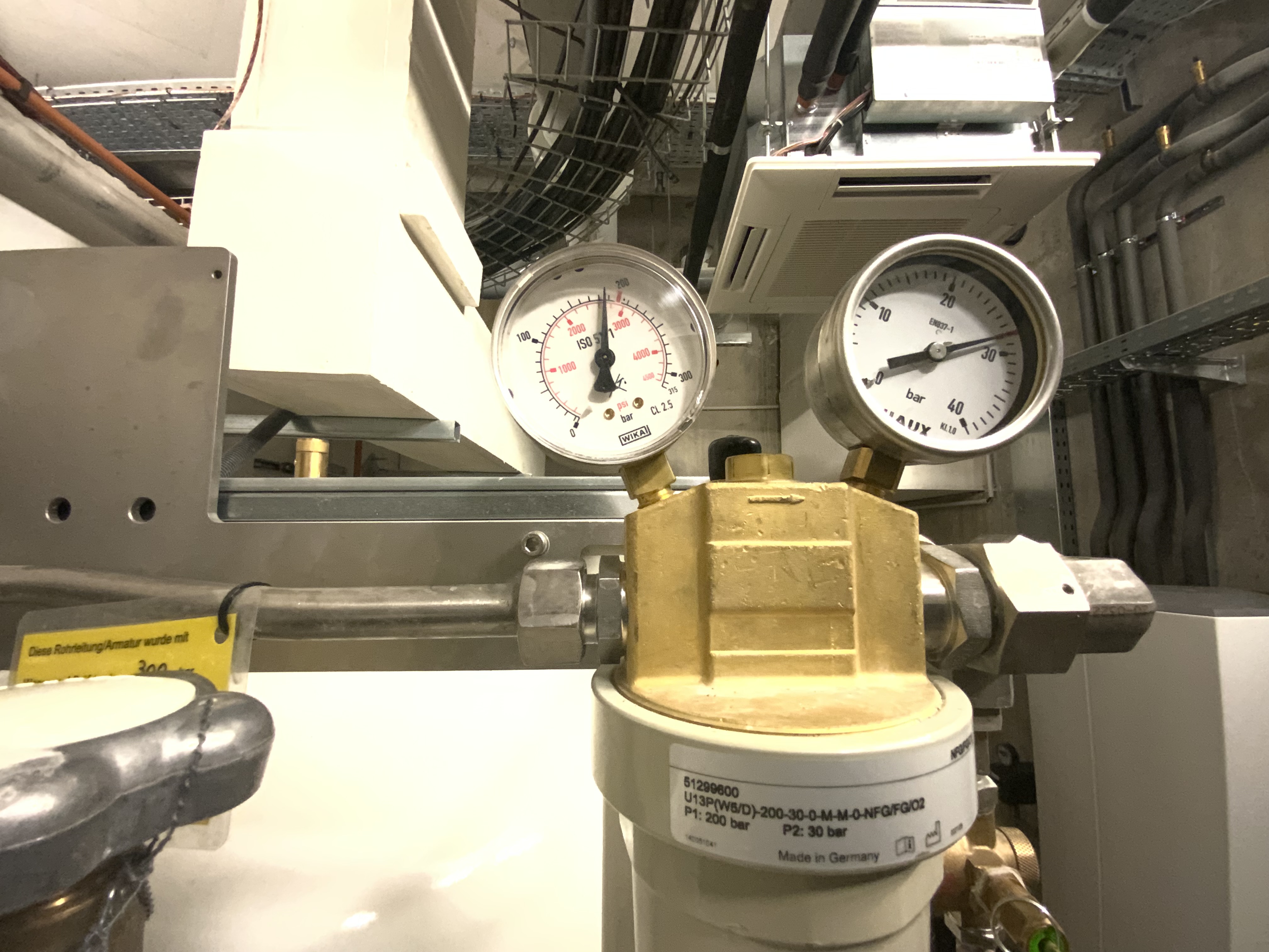
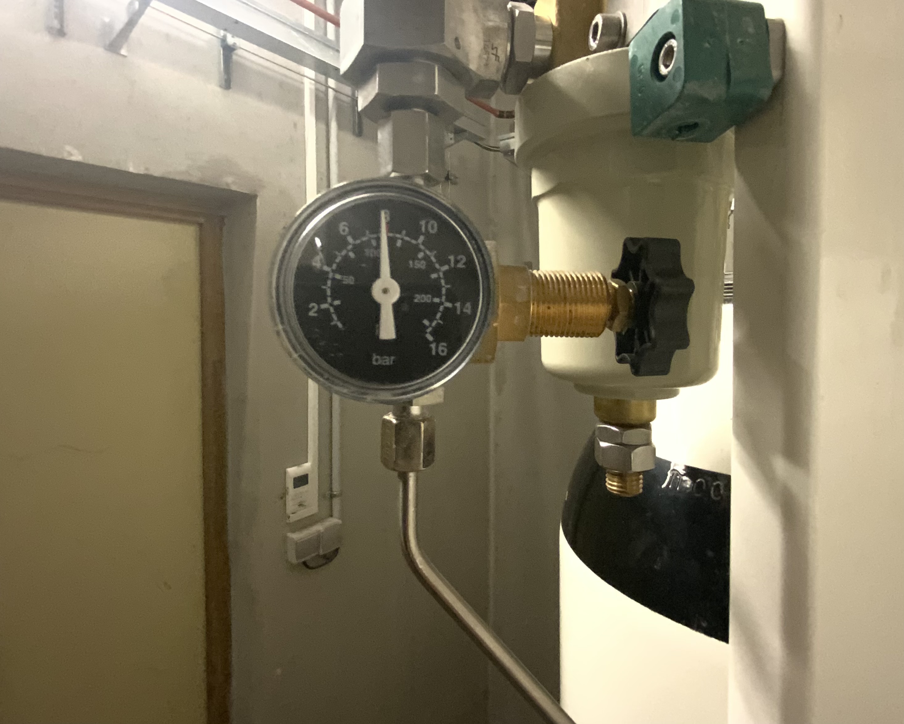
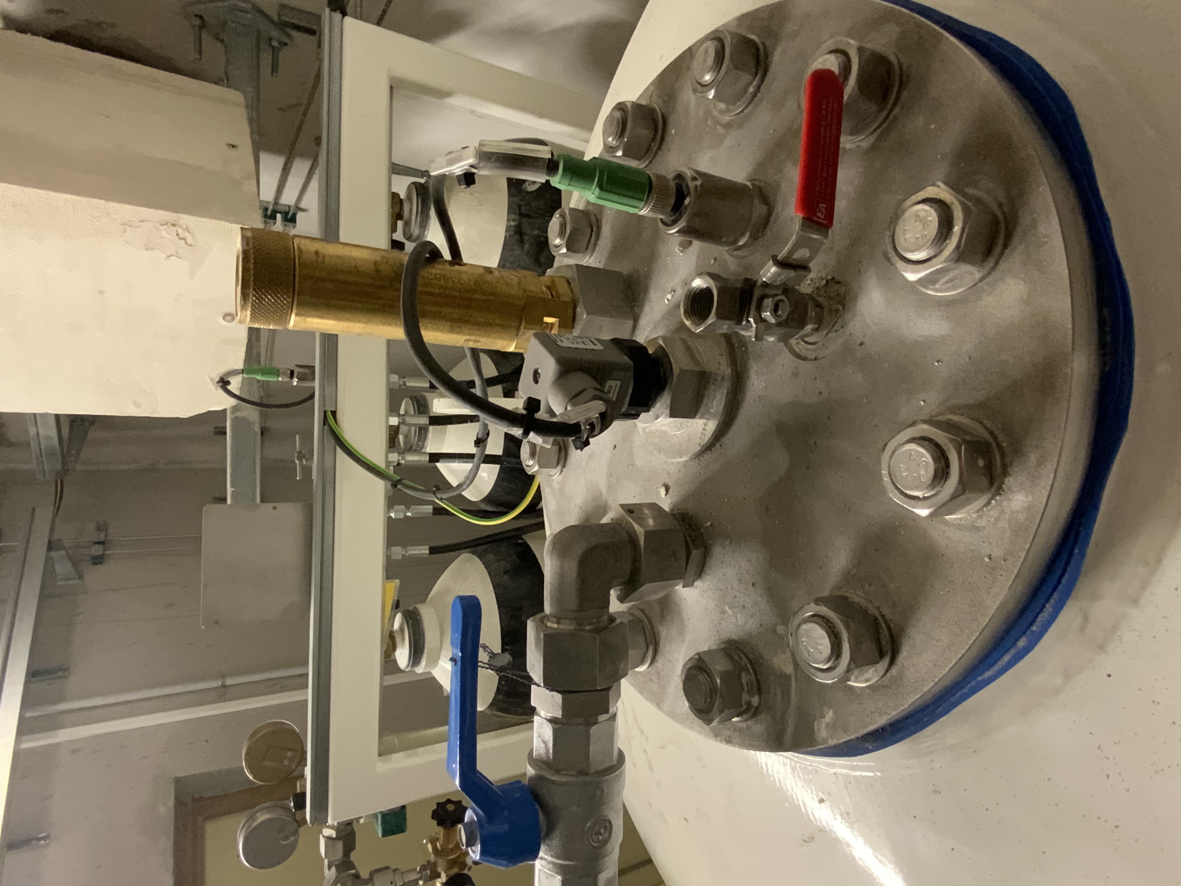
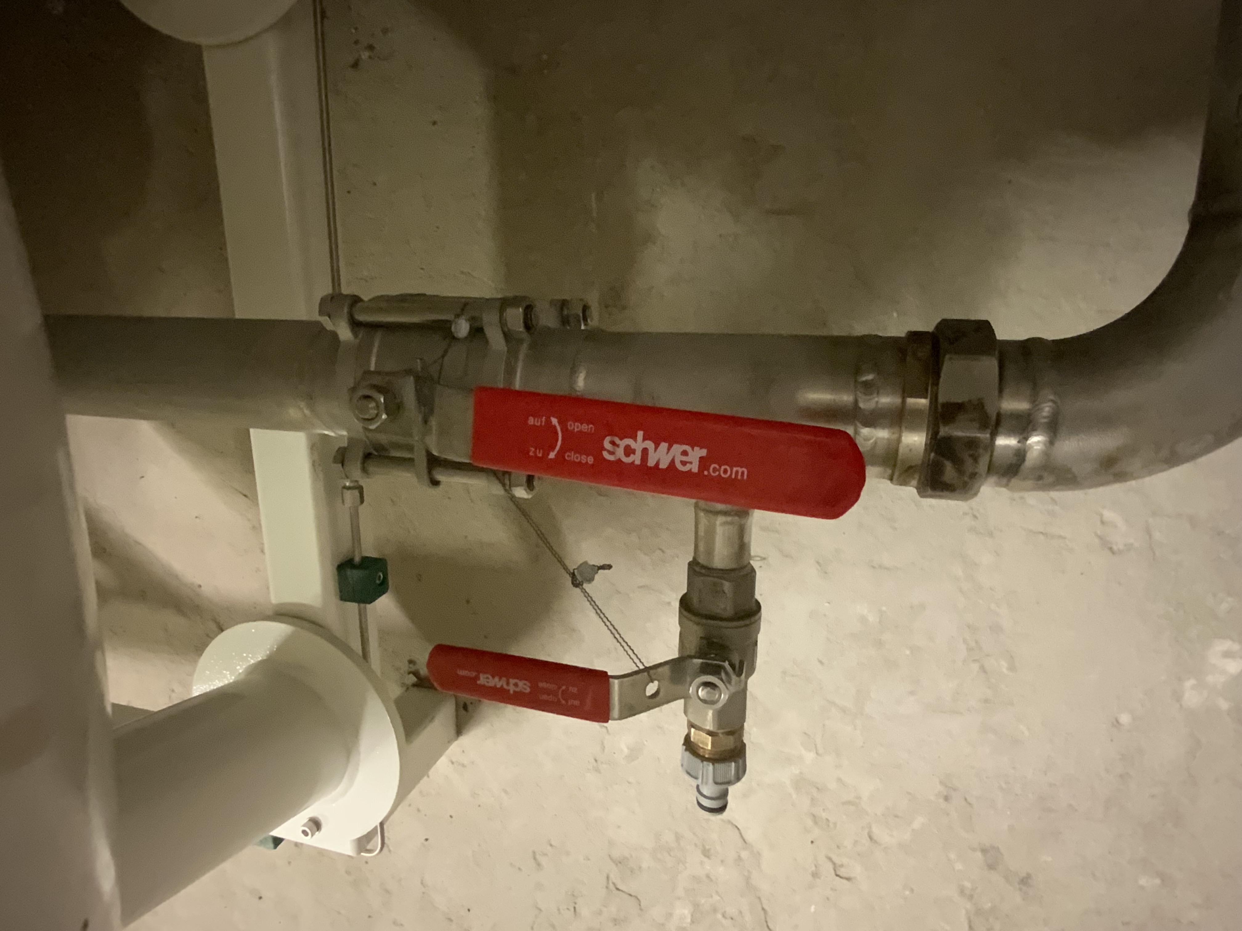
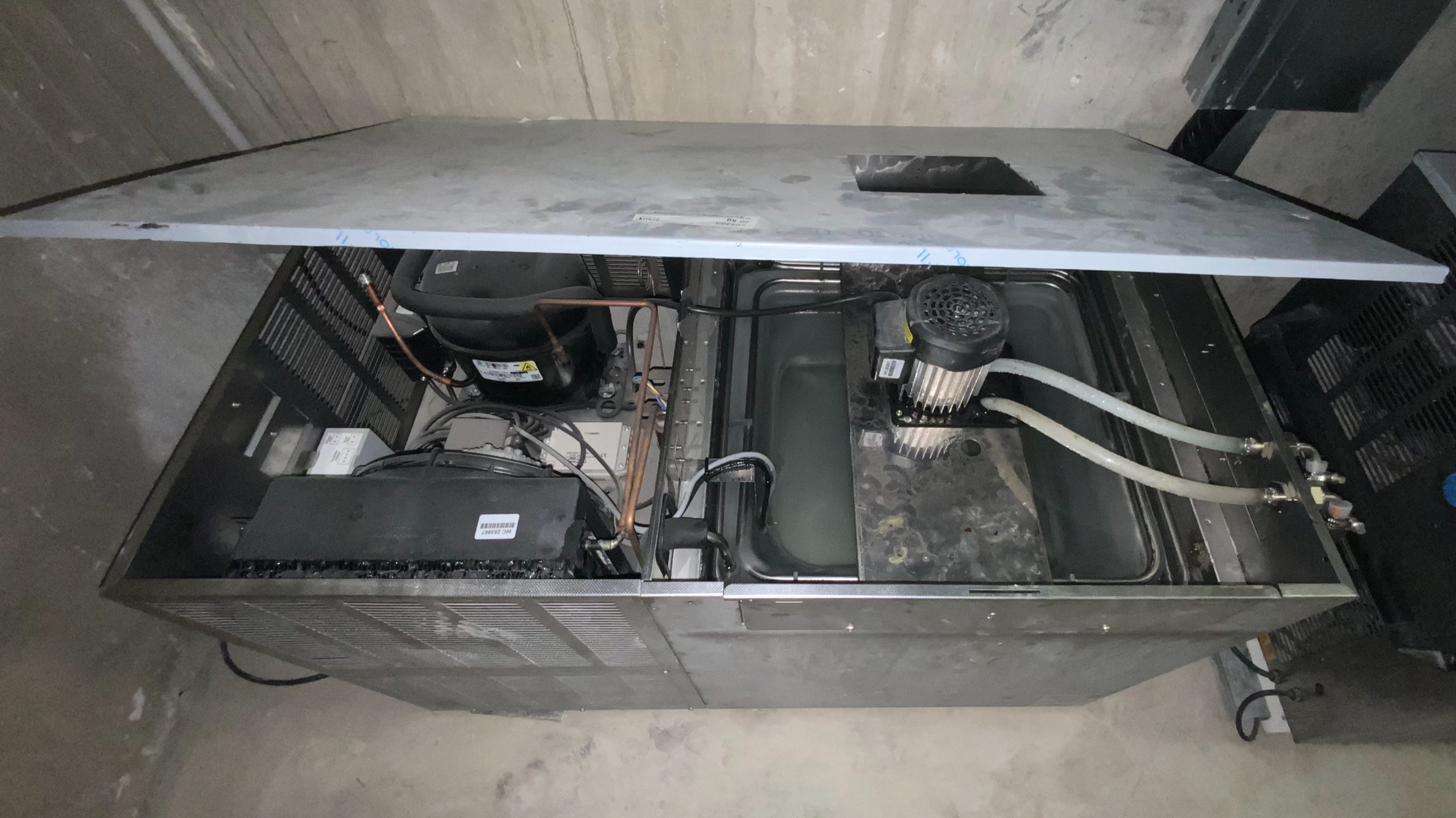
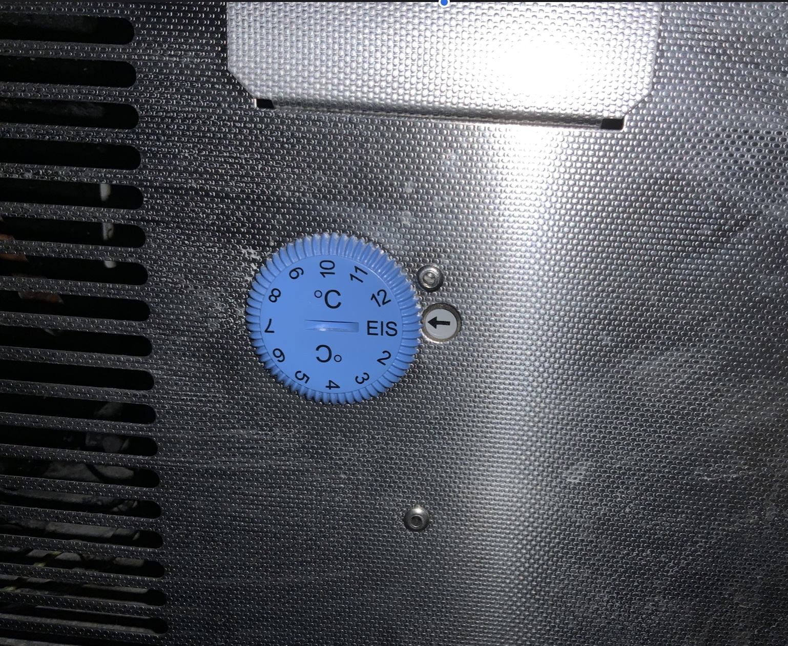
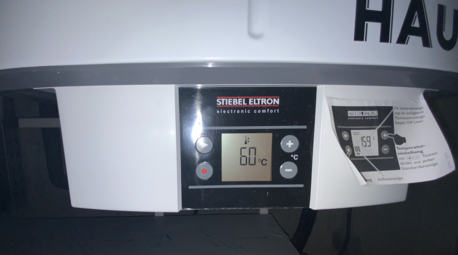
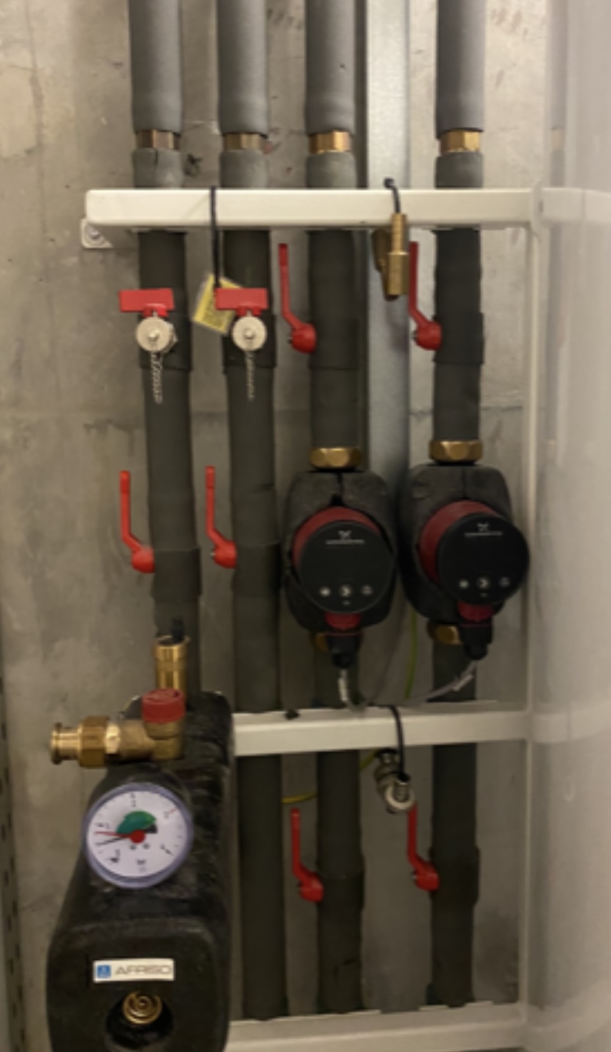
TABLEAU PNEUMATIQUE (TCPN)
-
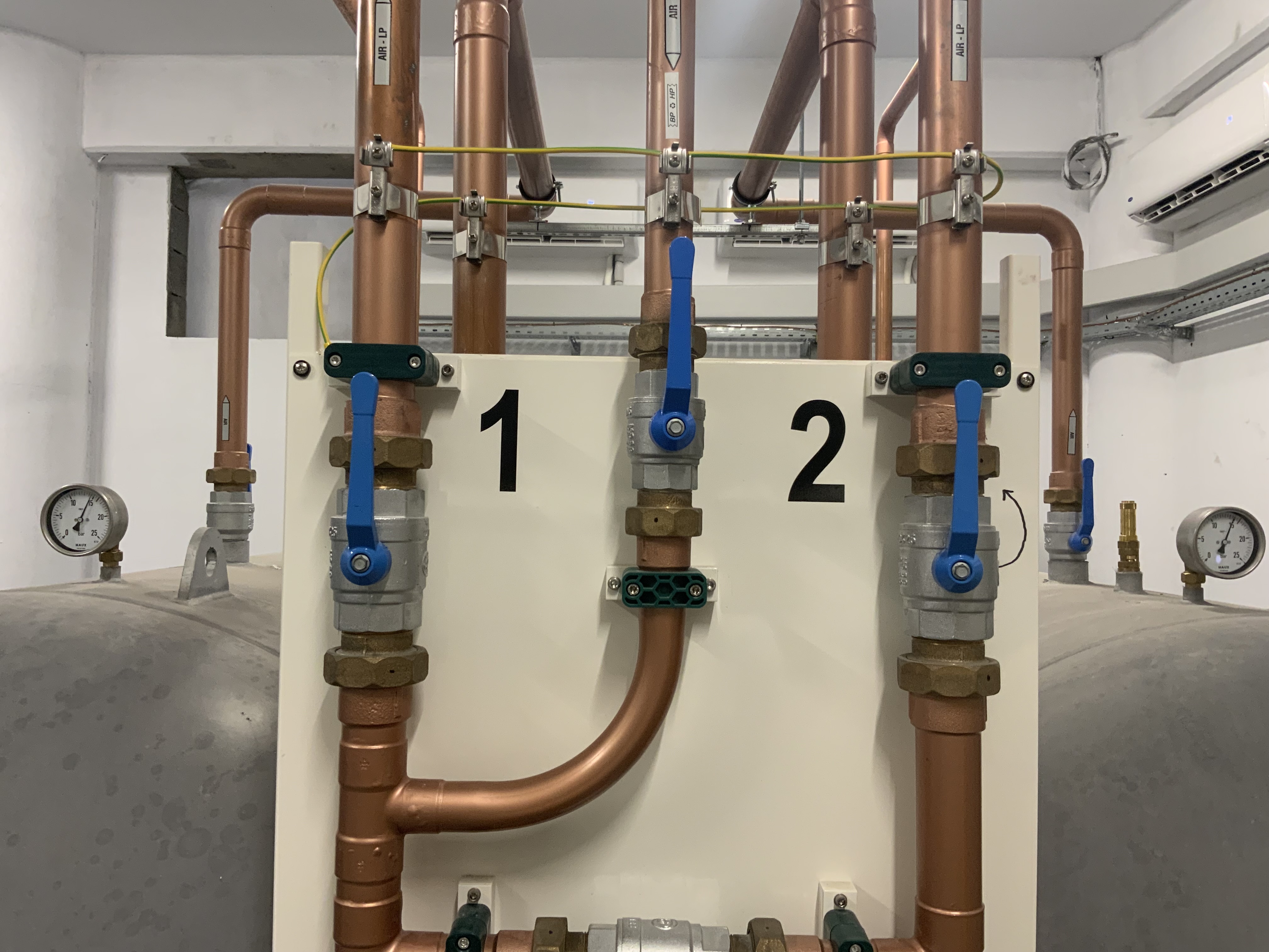
Vannes AIR BP 1 & BP 2 : Ouvrir
-
-
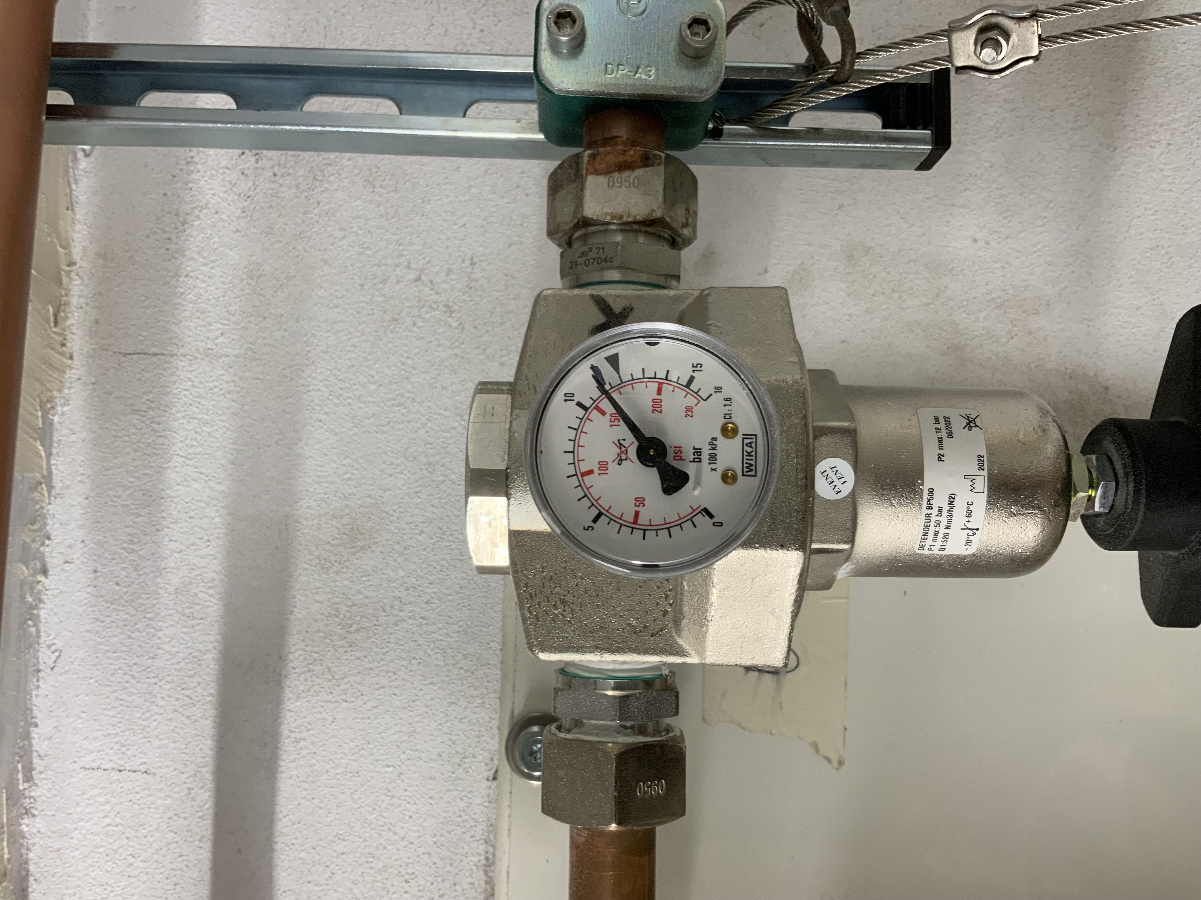
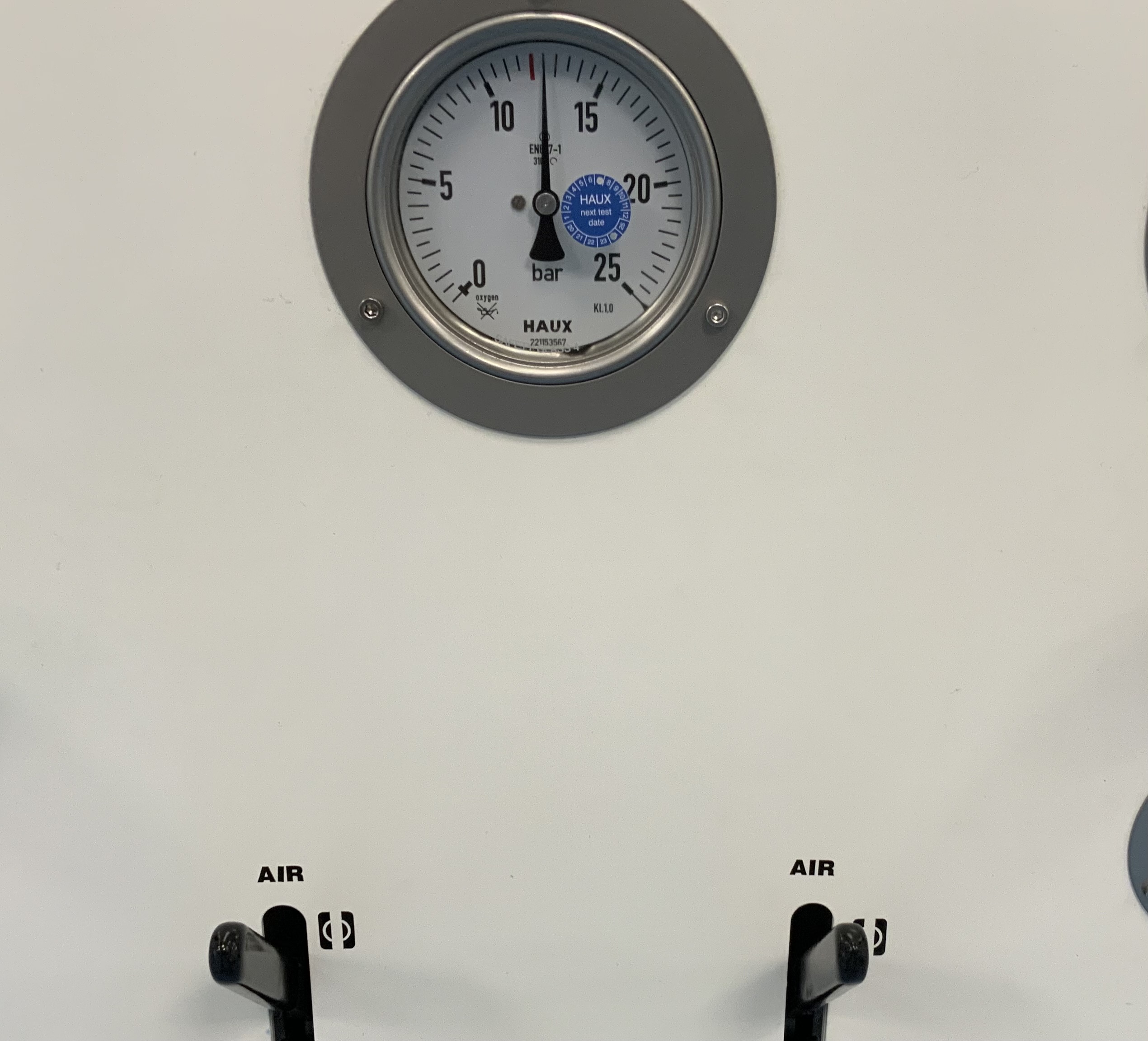
Manomètre Air BP
-
undefined
-
Pression Air BP
-
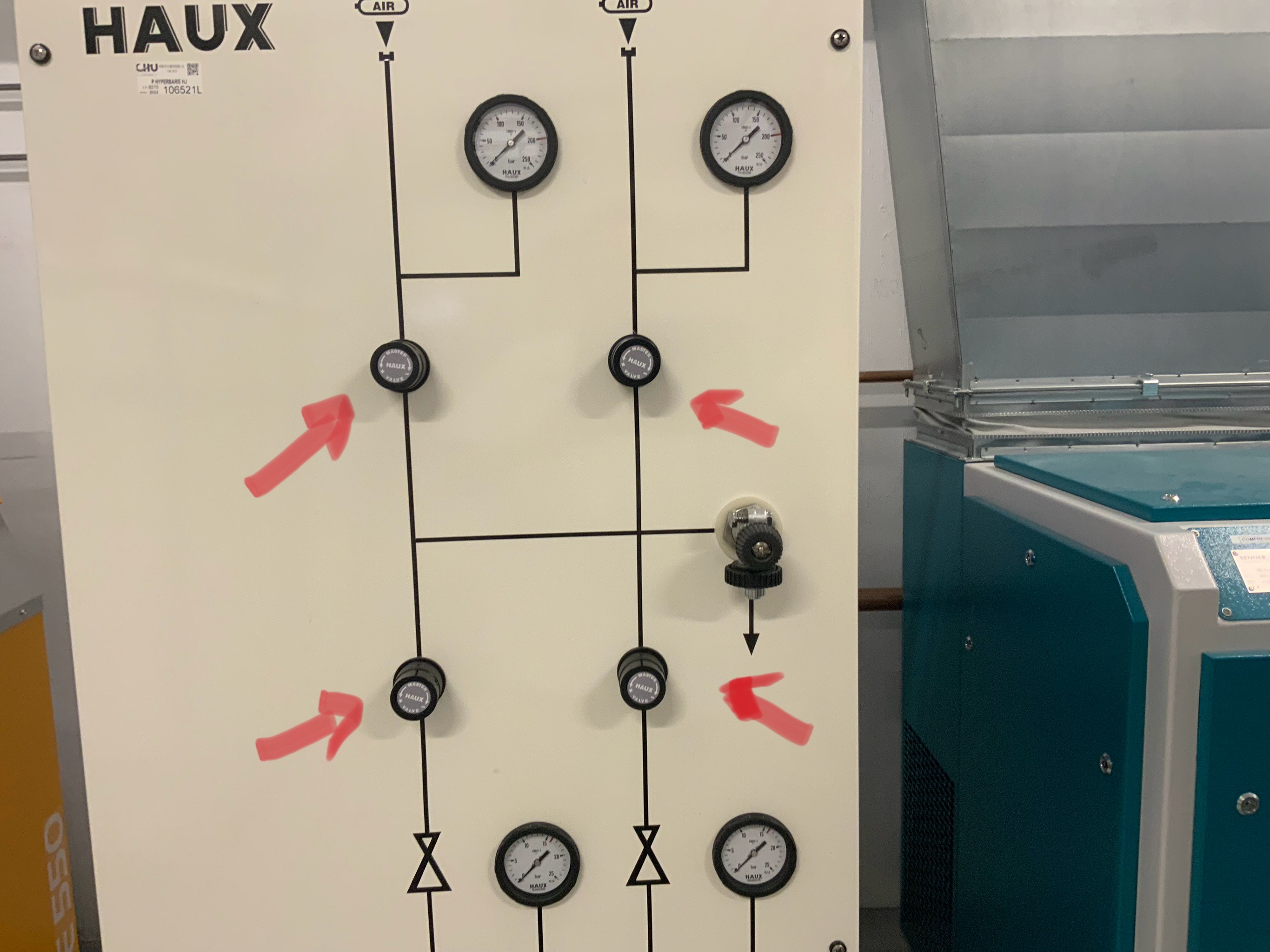
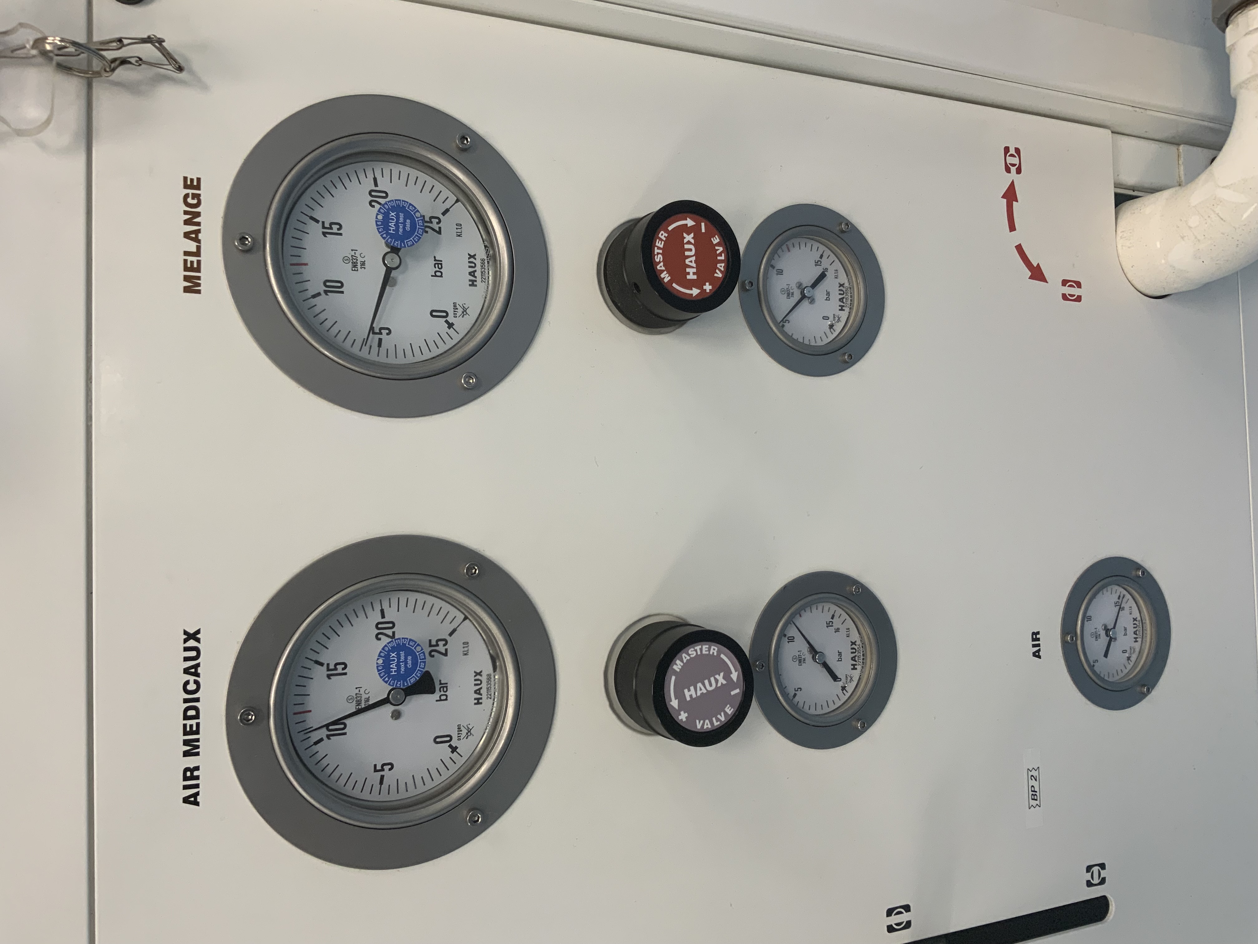
Mastervalve vide & Mastervalve O2 (10-12b) : ouvert
-
-
Masterv Air (10-12b) : ouvert
-
-
Sélecteurs sur décomat X6
-
CHAMBRES HYPERBARES
-
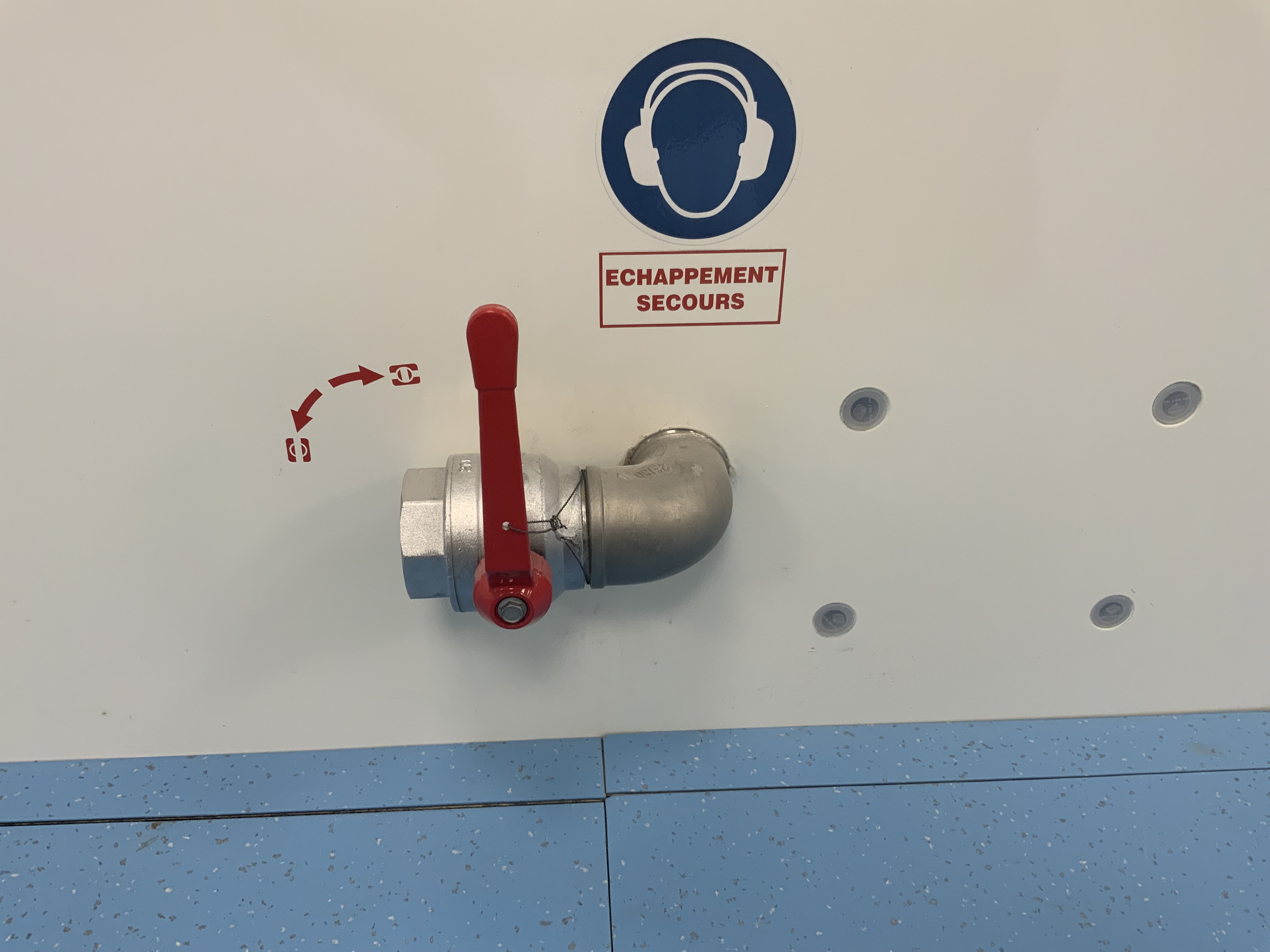
Vannes échappement secours plombées x3 : Fermées
-
-
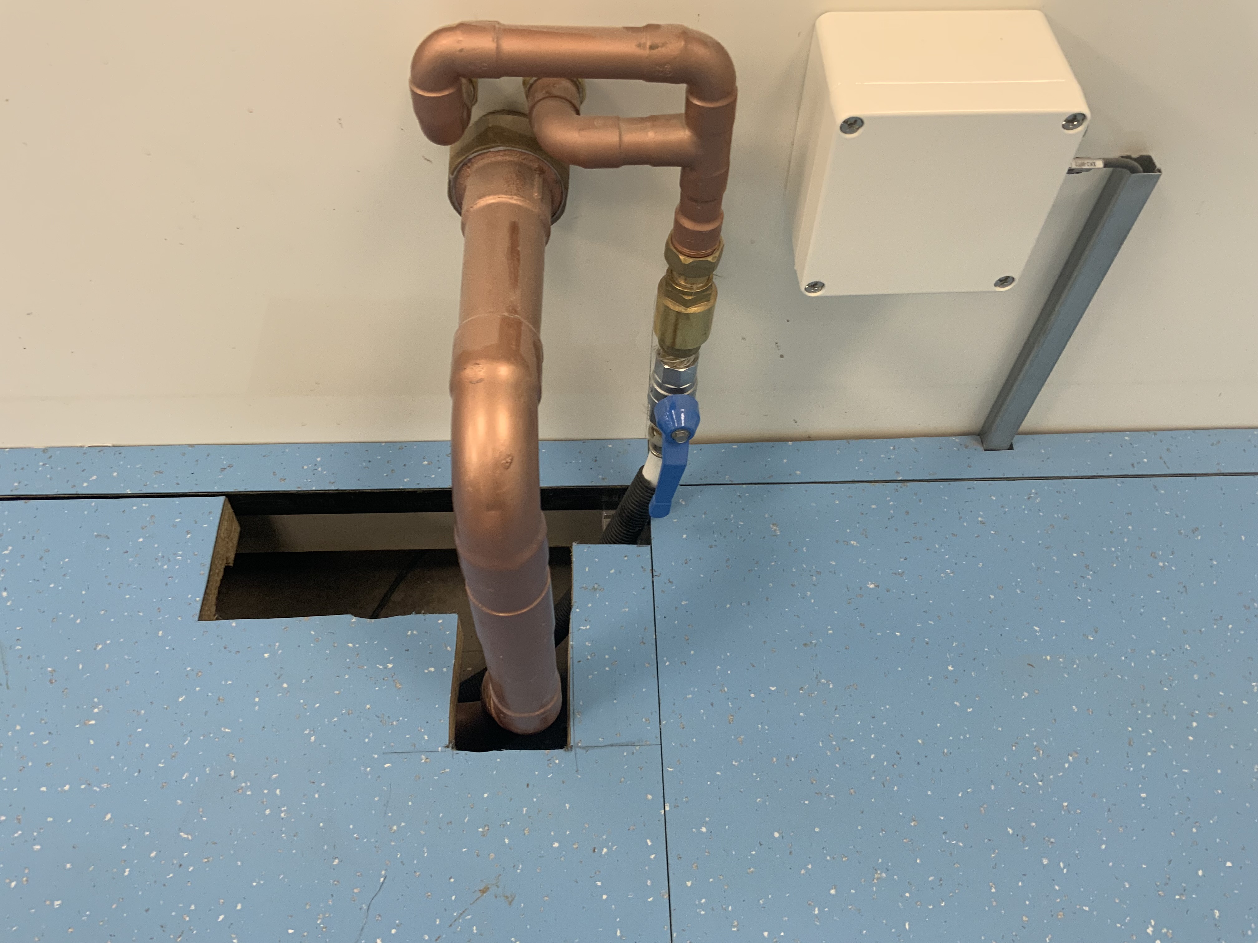
Vannes évacuation des eaux x2 : Ouvertes
-
-
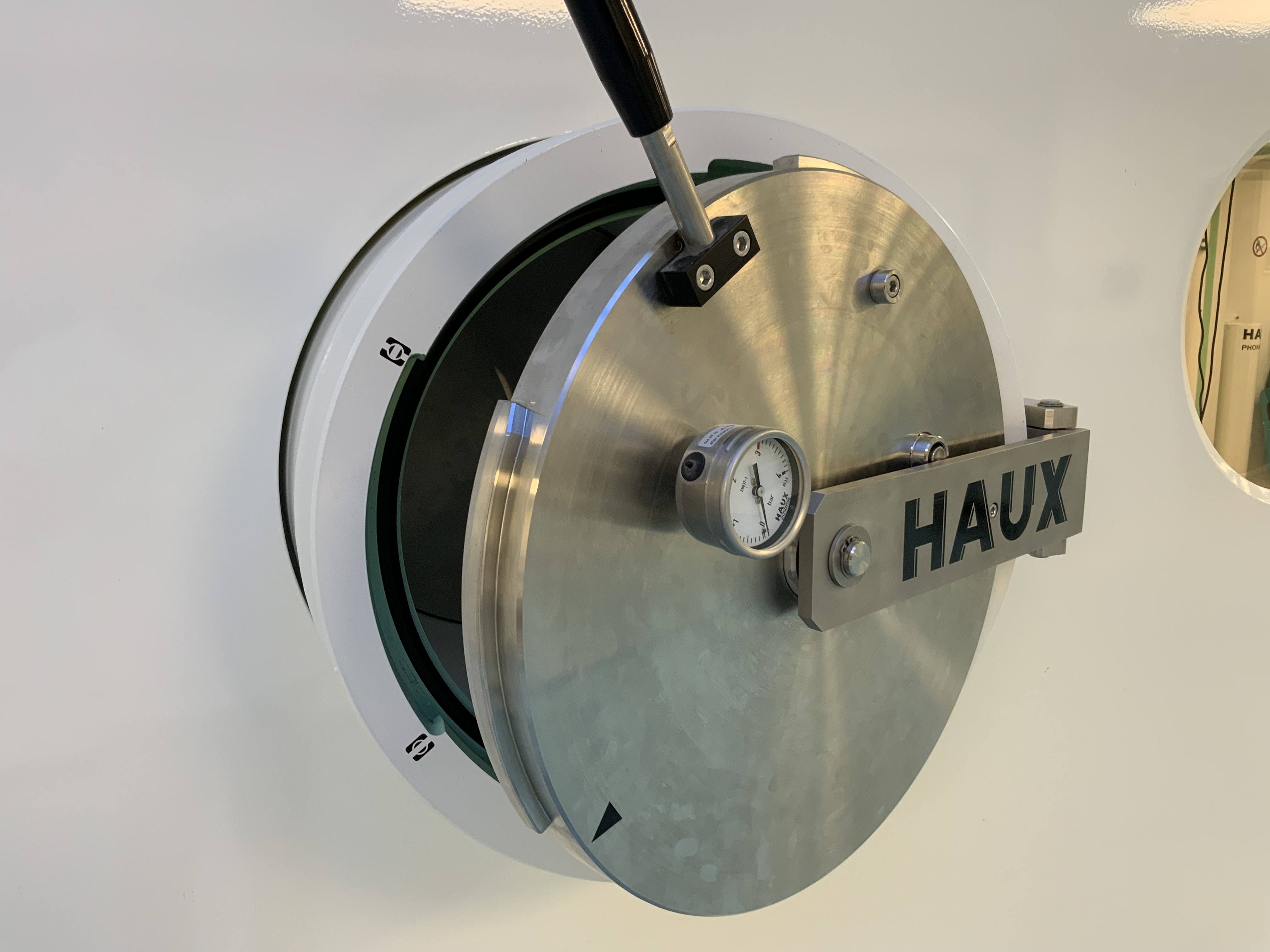
CH 1 : SAS extérieur ouvert
-
-
CH 1 : Bouton incendie OK
-
-
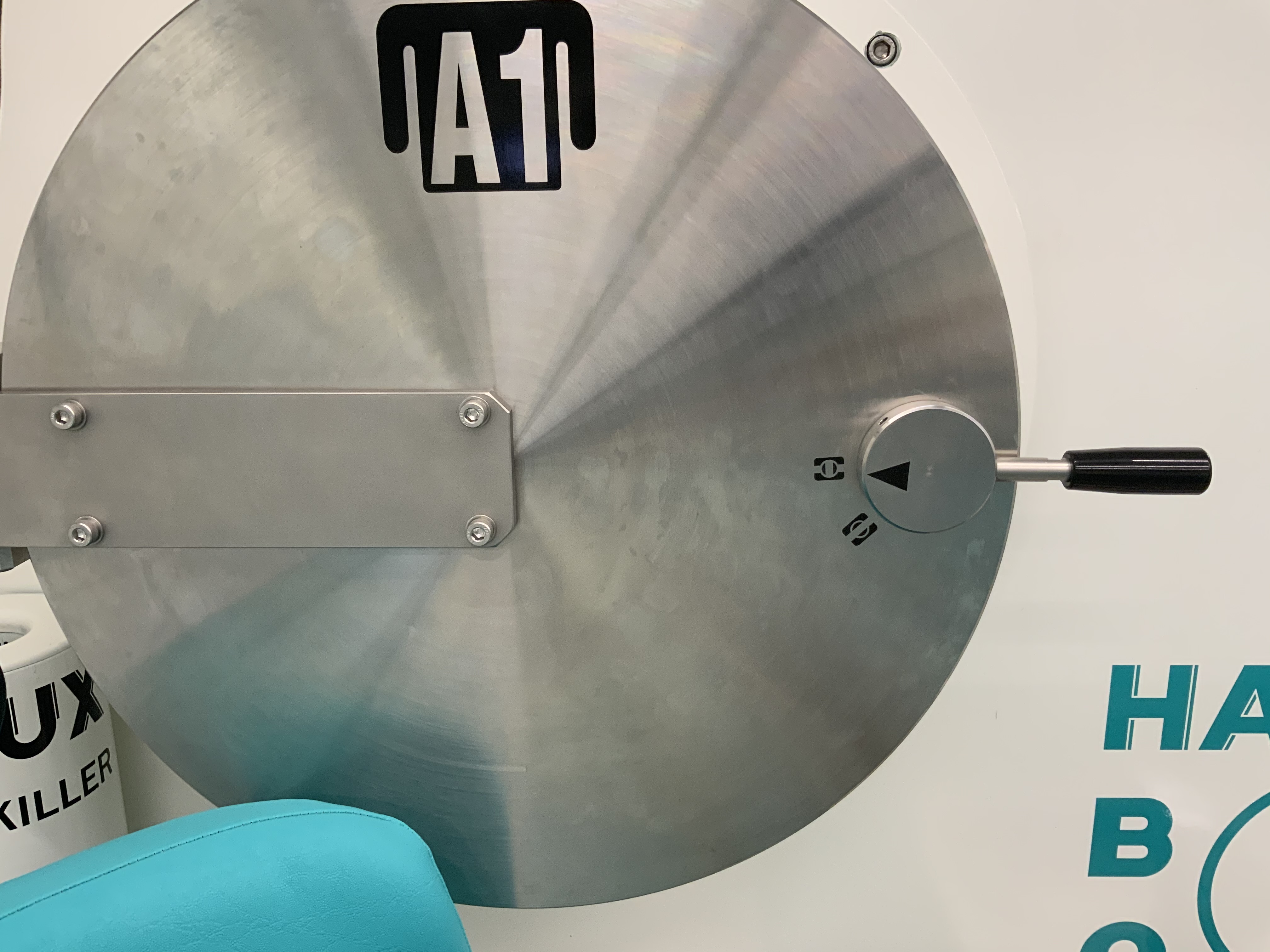
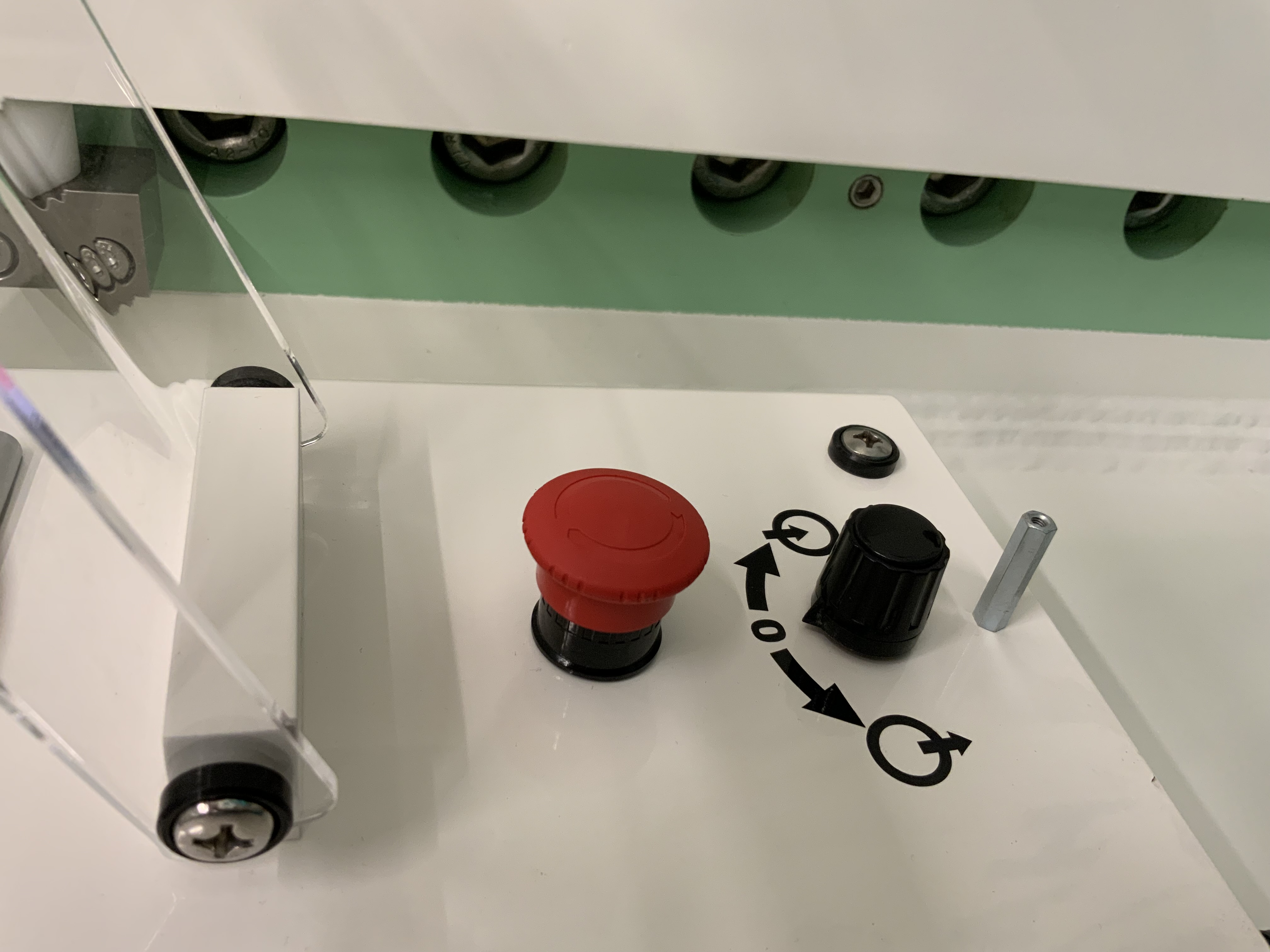
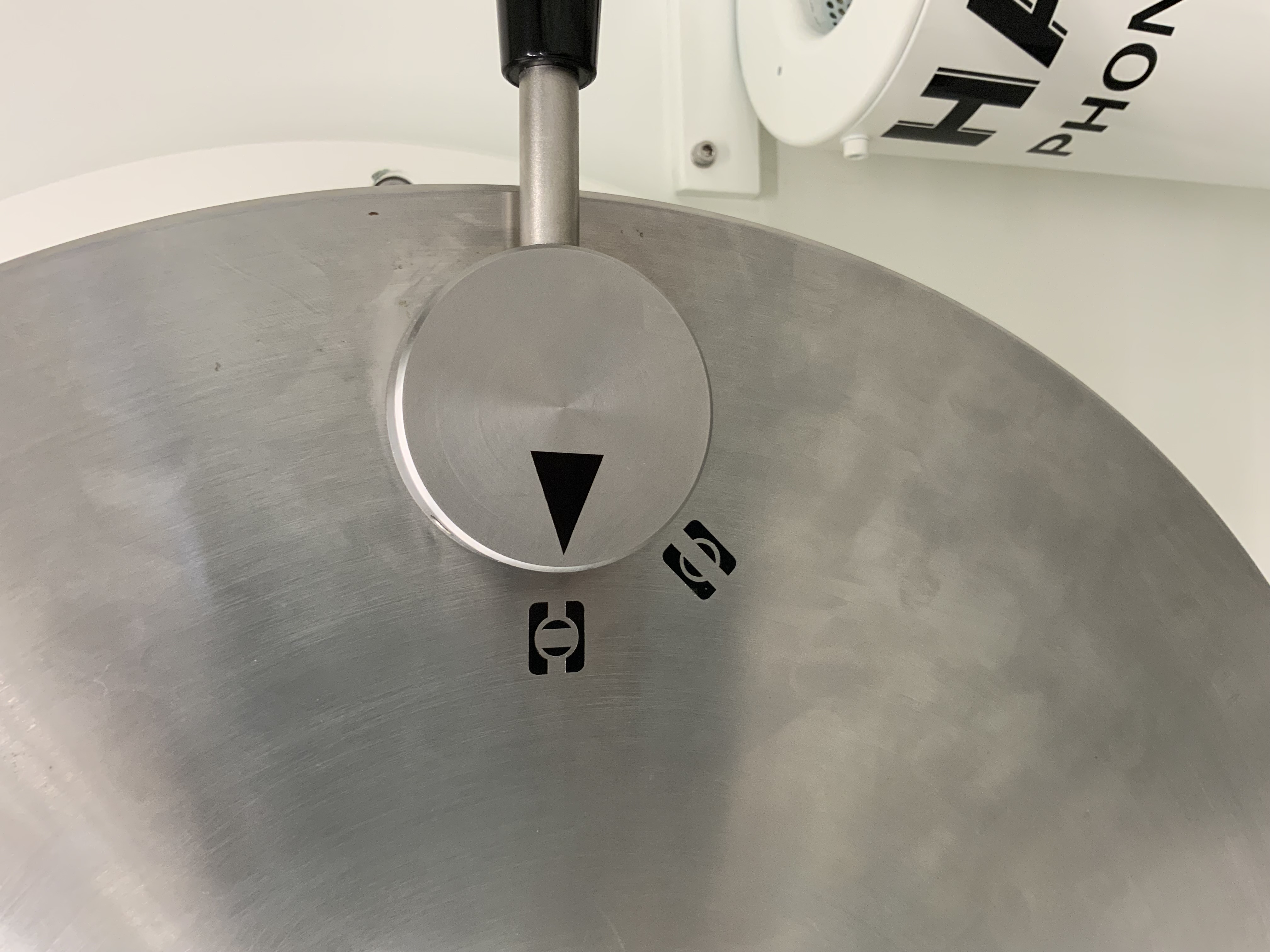
CH 1 : Pilotage interne : Bouton Ok et Molette à niveau
-
-
CH 1 : Bus fonctionnel
-
-
CH 1 : SAS à médicament fermé
-
-
CH 1 : Bouton incendie OK
-
-
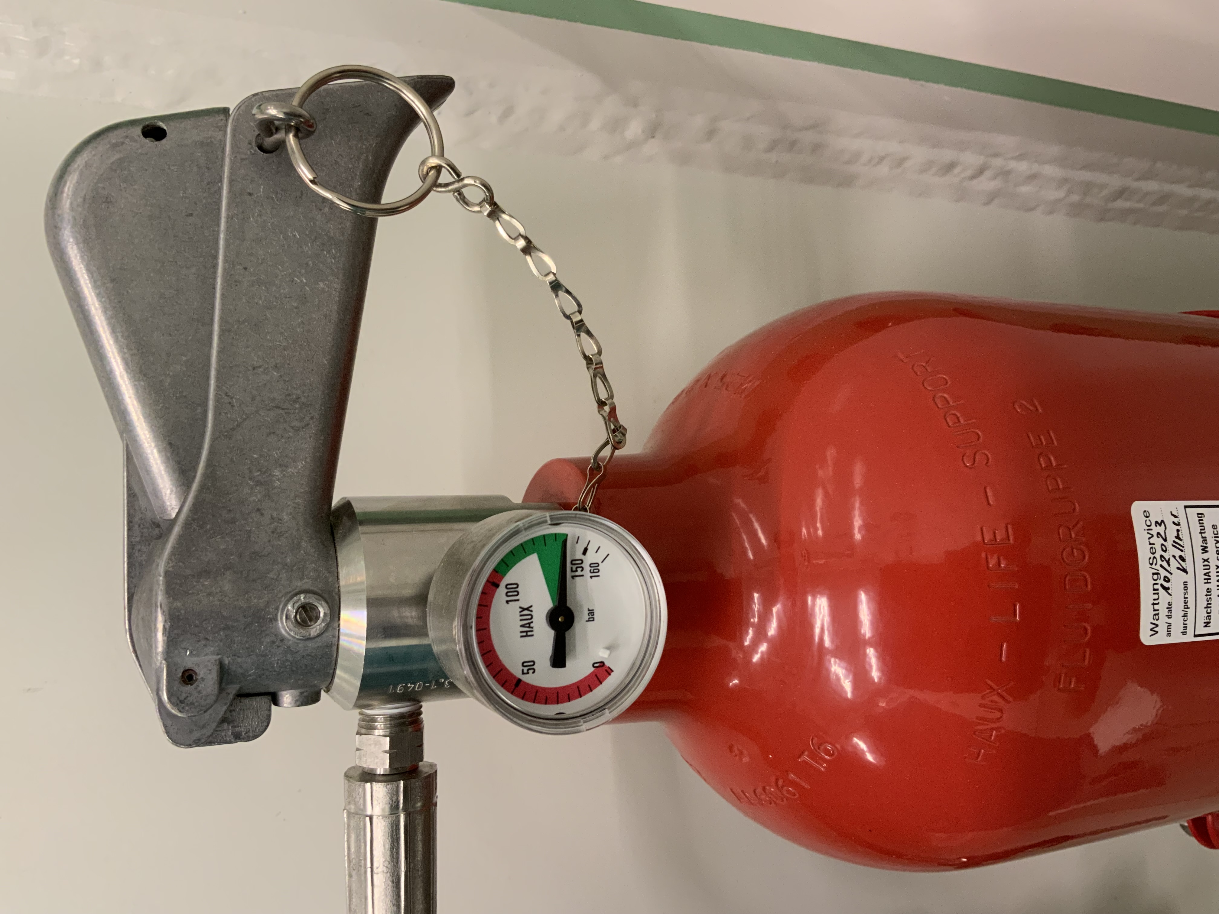
CH 1 : Extincteur 150 bars
-
-
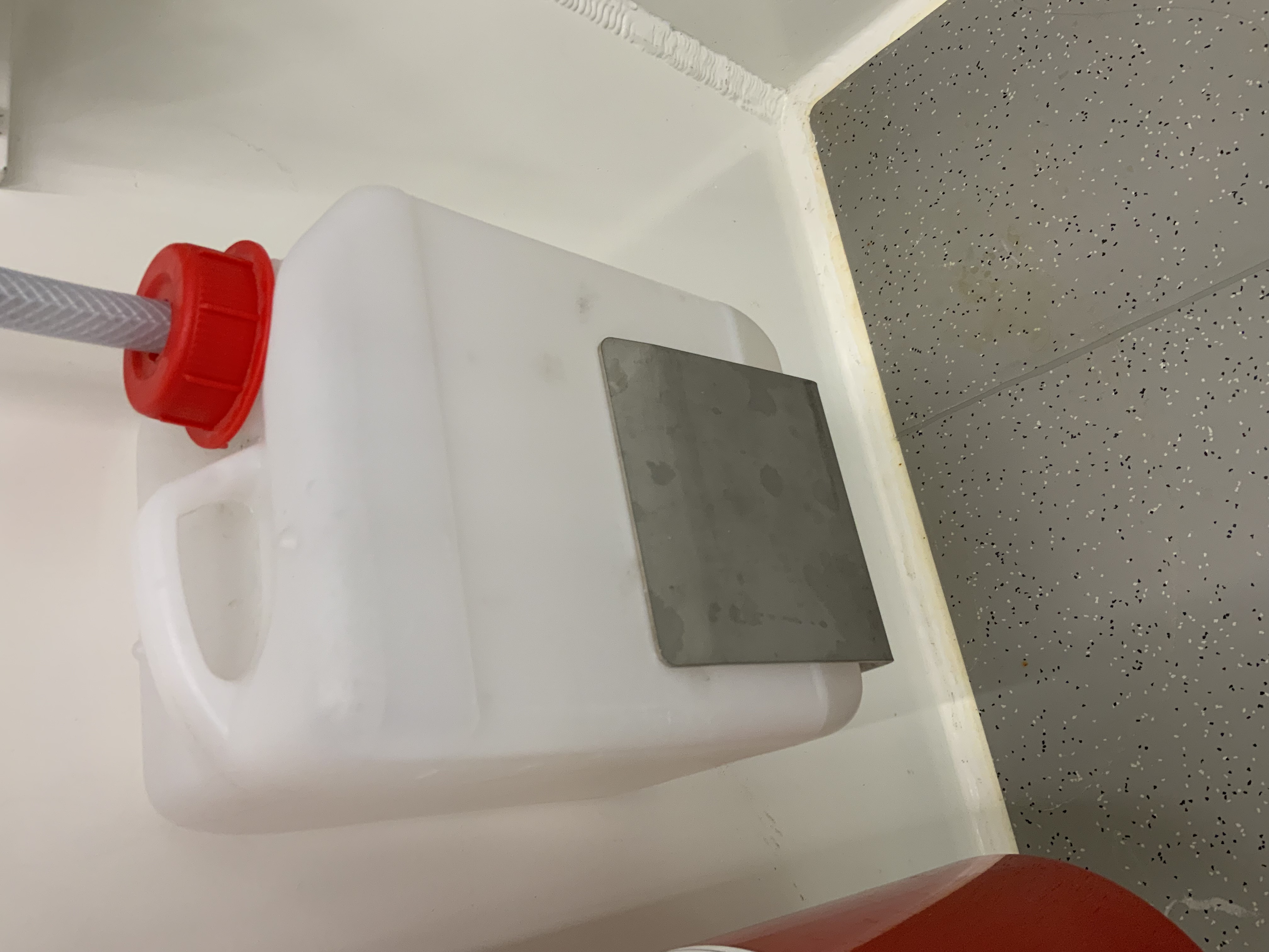
CH 1 : Condensat de Clim : OK
-
-
CH 1 : Valise/sac d’urgence présent
-
CH1 : Vanne de purge de la Porte du SAS : fermée
-
-
SAS Personnel : Vanne de purge avec la CH 1 : Fermée
-
-
SAS Personnel : Bouton incendie OK
-
-
SAS Personnel : Pilotage interne : Bouton et molette OK
-
-
SAS : Bus fonctionnel
-
-
SAS Personnel : Vanne de purge et CH 2 : Fermée
-
-
CH 2 : Vanne de purge et SAS : Fermée
-
-
CH 2 : Extincteur 150 bars
-
-
CH 2 : Bouton incendie OK
-
-
CH 2 : Condensat de Clim : OK
-
-
CH 2 : SAS médicament : fermé
-
-
CH 2 : Pilotage interne : Bouton et Molette OK
-
-
CH 2 : Bouton incendie OK
-
-
CH 2 : Bus fonctionnel
-
-
CH 2 : Valise/Sac d’urgence présent


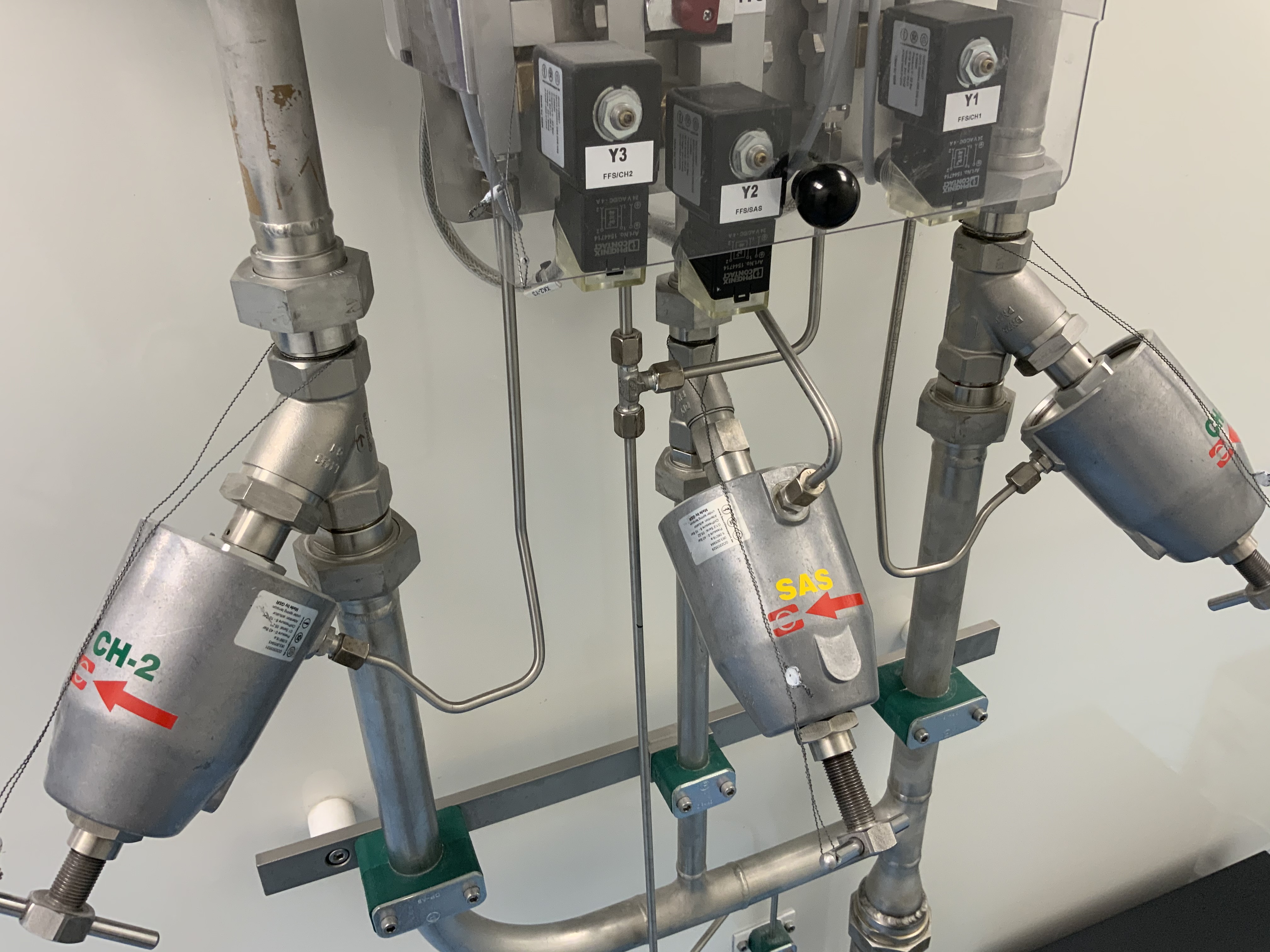
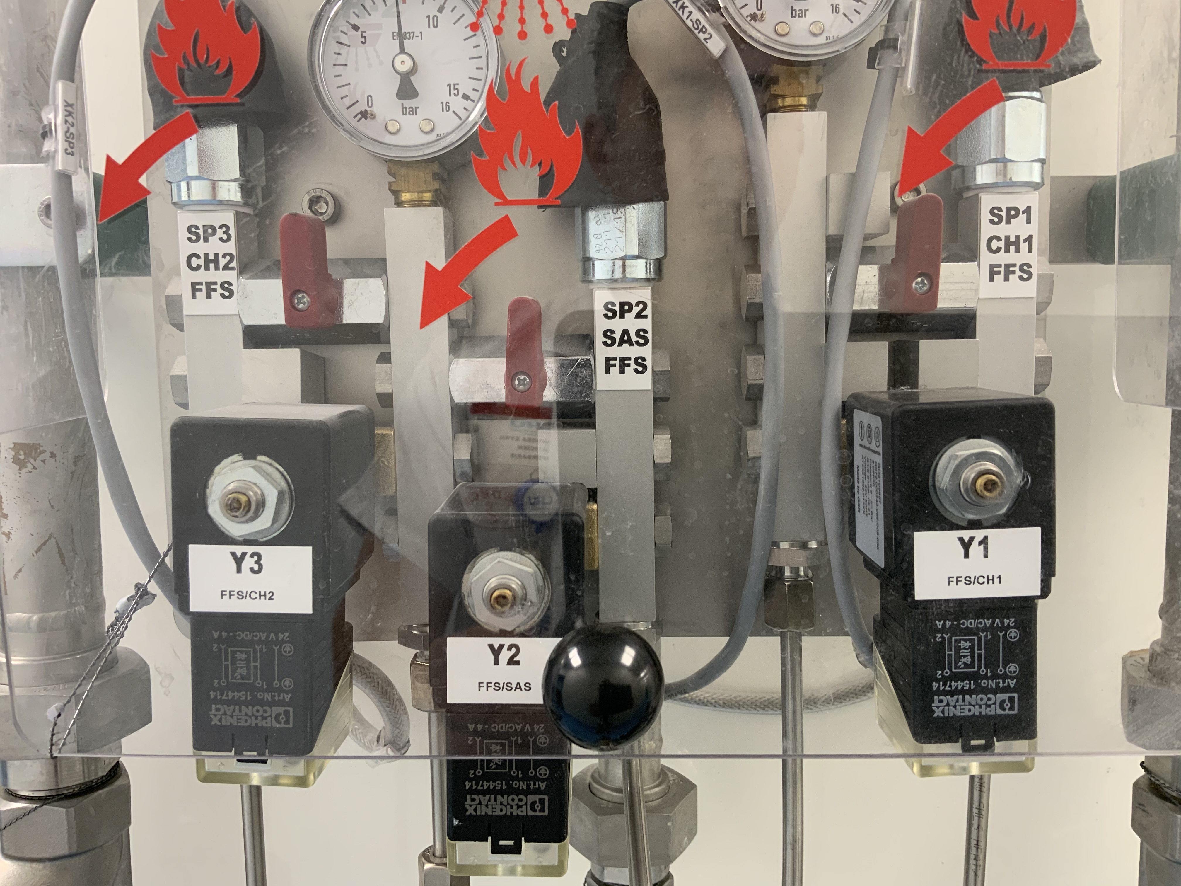
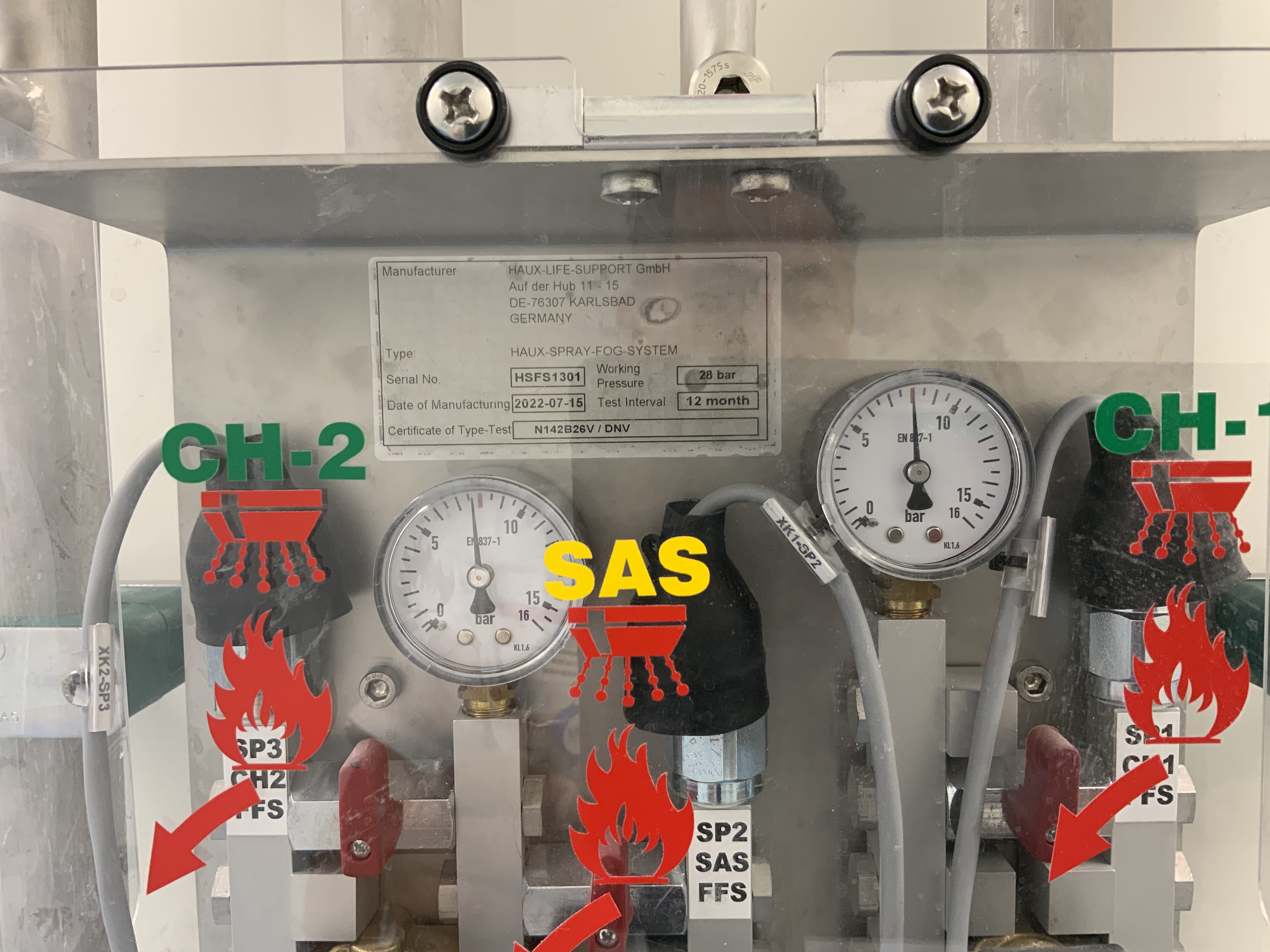
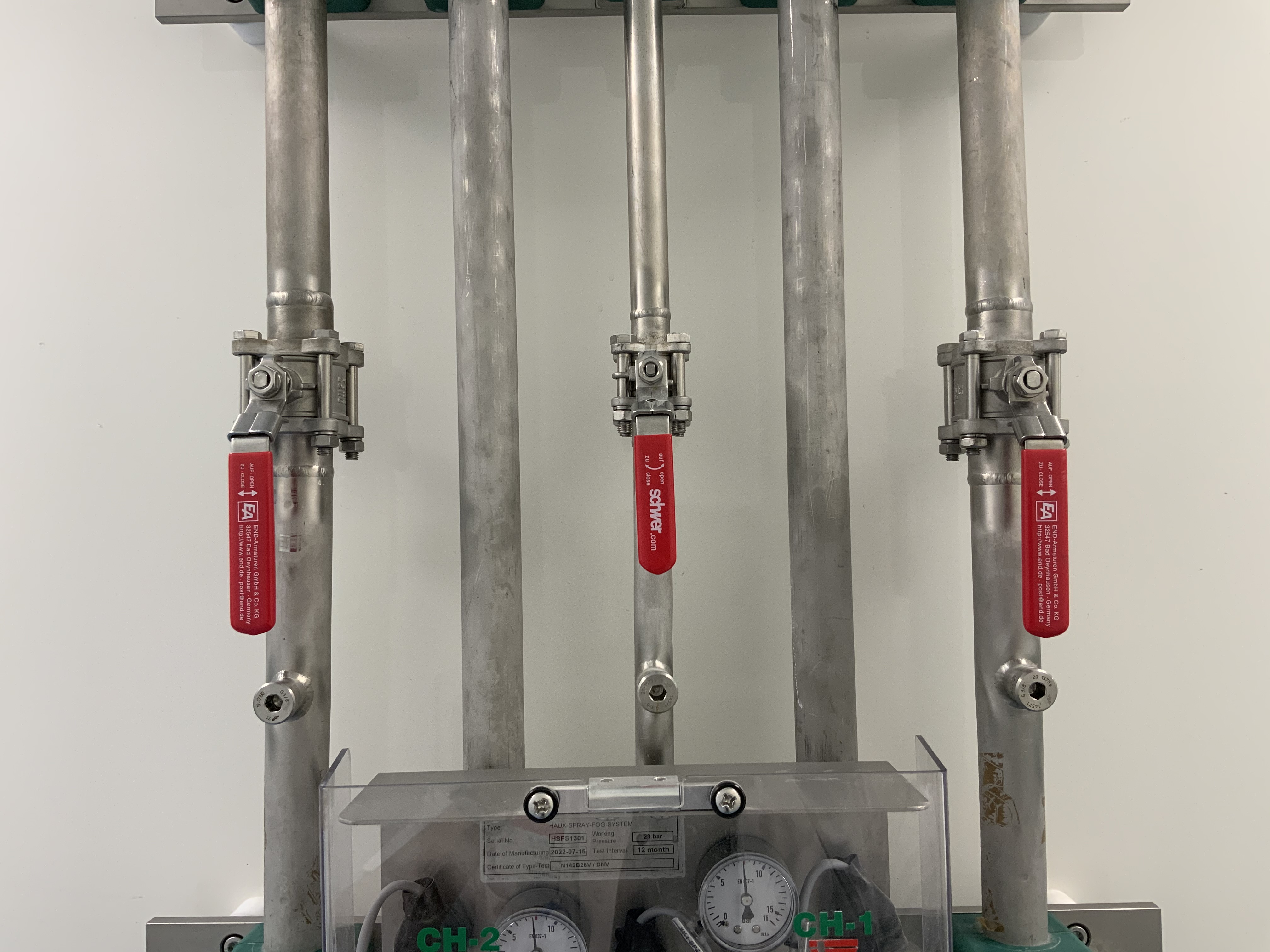
EXTÉRIEUR DE LA CHAMBRE
-
Système incendie : Manuelles plombées
-
-
Système incendie : électrovannes OK
-
-
Système incendie : Manomètres 8bars
-
-
Système incendie : Vannes d’aspersion ouvertes
-
-
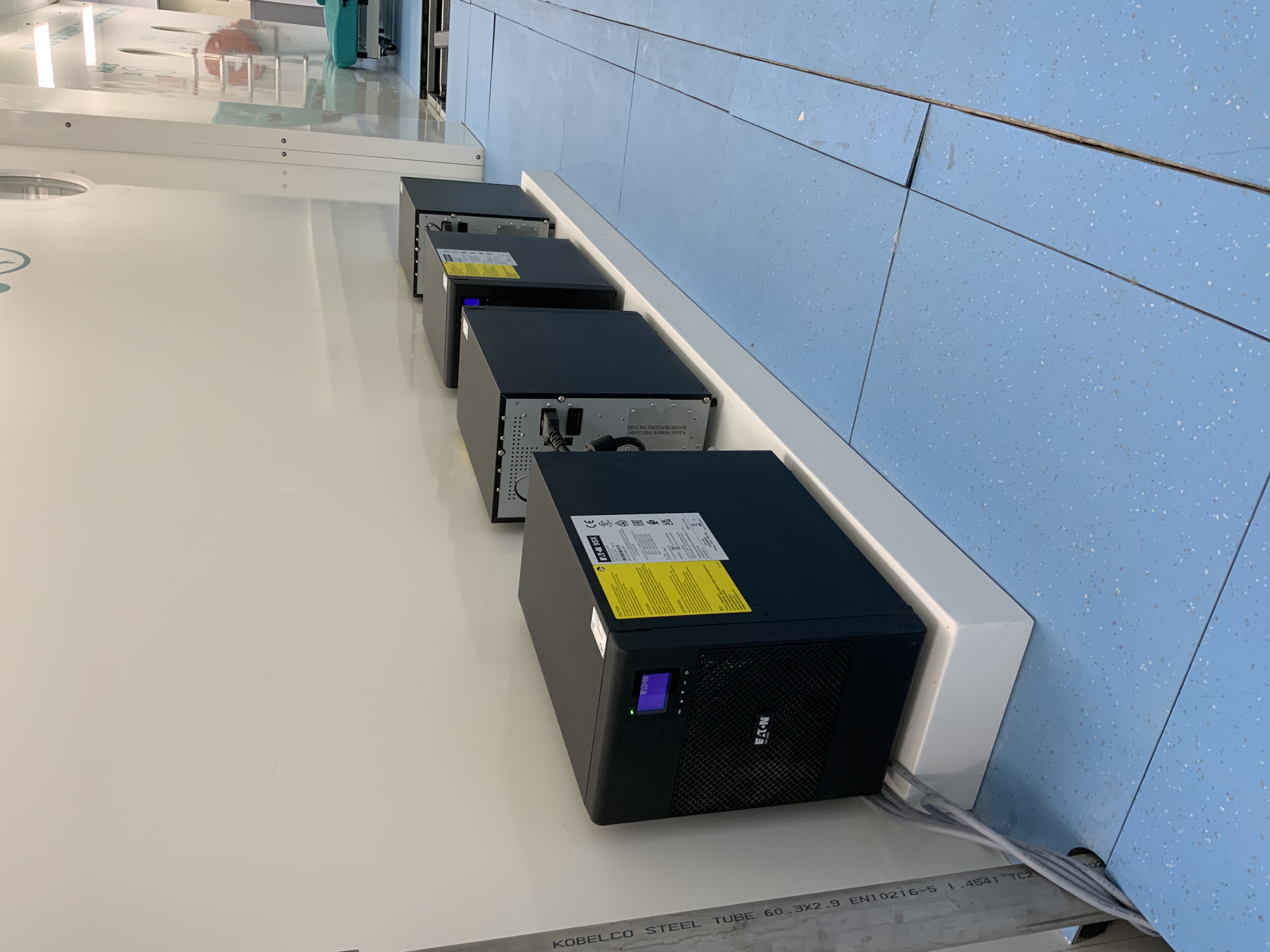
Onduleur: fonctionnel
-
PUPITRE CAISSON
-
-
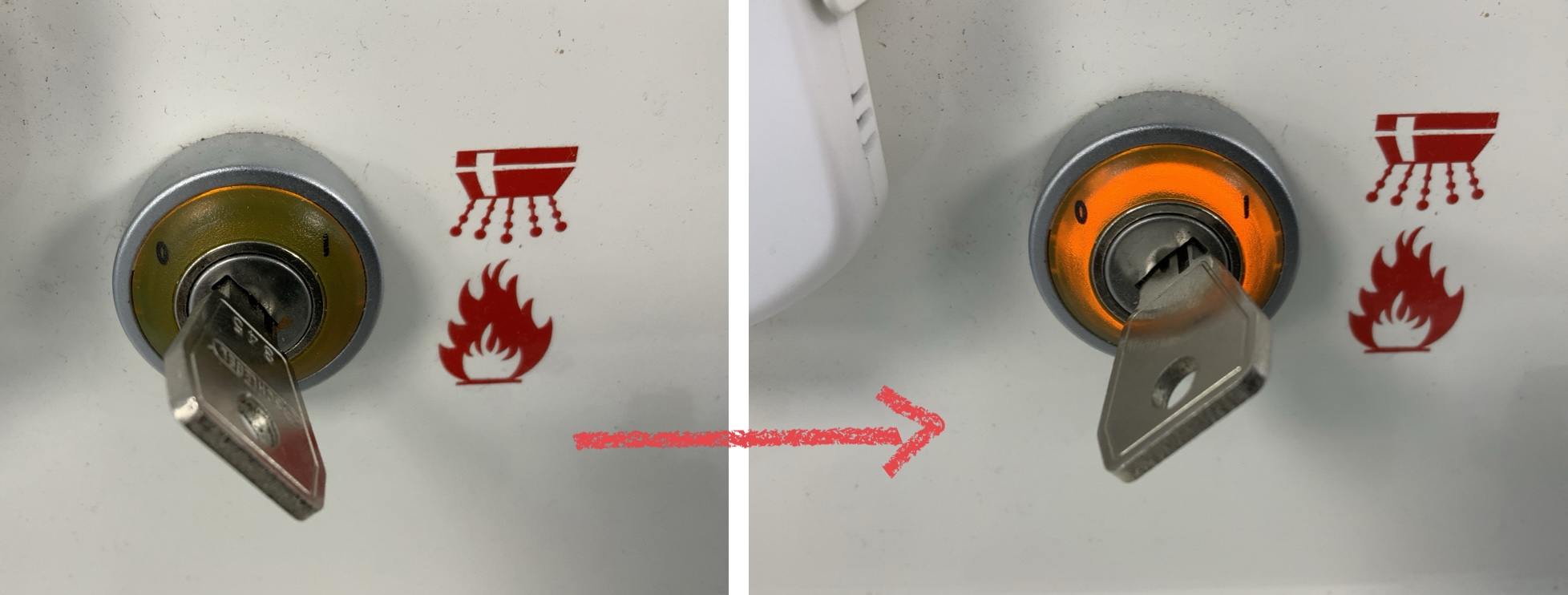
Clef incendie : ON
-
-
Décomat : CH 1 + CH 2 : activé & SAS : main
-
-
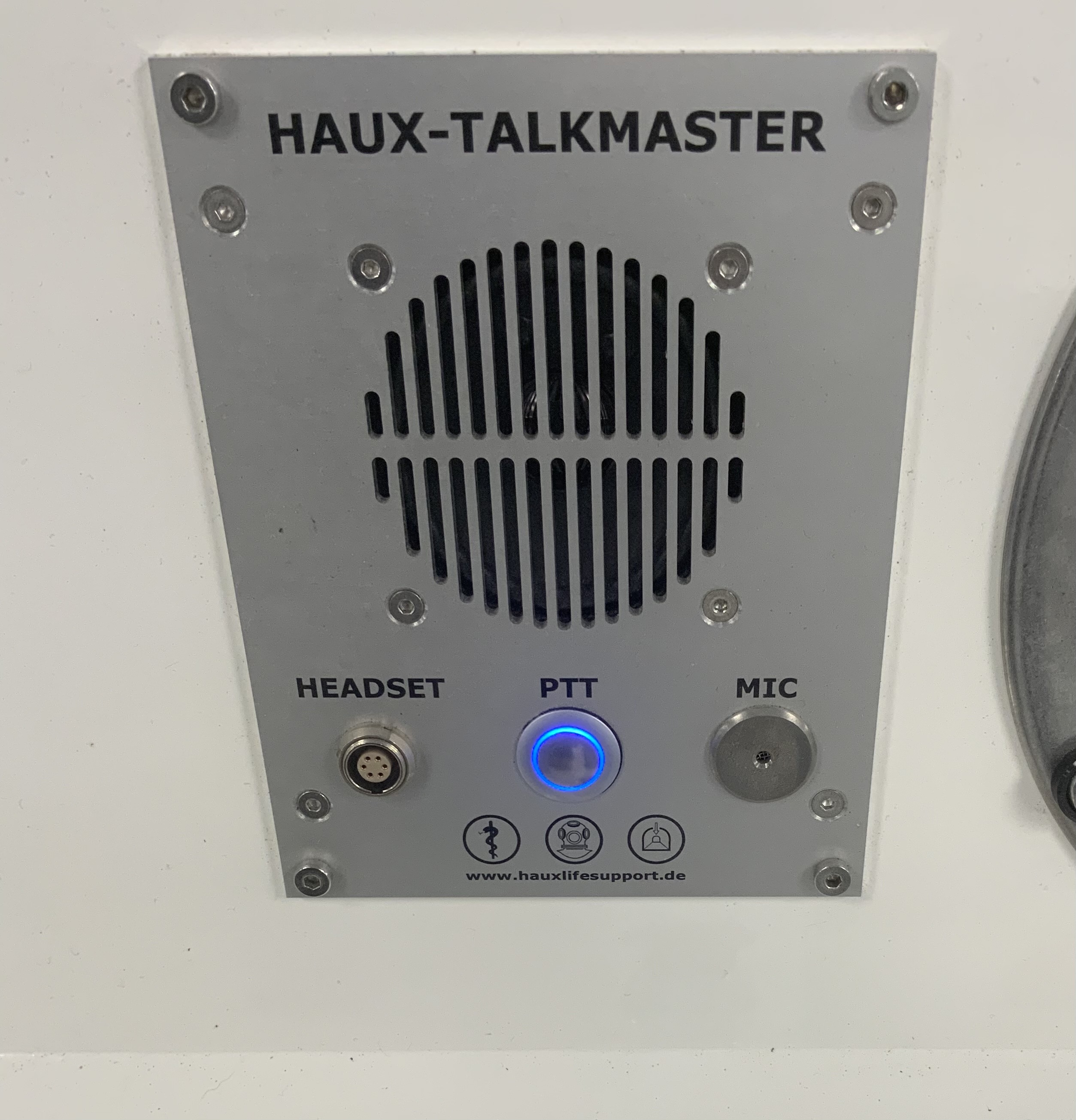
Communication : fonctionnelle
-
SIGANTURE
-
Add signature


