Title Page
-
Document nr
-
Description
-
Site conducted
-
Prepared by
-
Date
-
Site Location
-
Client Name
-
Other Comments
A. Client Handover
-
Grid Lines and Datum, Safe area of work, Skip ...
B. Drawings
-
Design, Details Drawings, Data Sheet & installation guide checked
QAC-Inspection Checklist
- 1. Breather Membrane Installation
-
Breather Membrane to spec seal /tape all joints with Tape
2. Aluminium Support C Channel & BRACKETS Installation
-
Channel & Top Hat fixed to SFS studs, GL/Datum; fixings to spec.SINGLE BRACKETS and DOUBLE BRACKETS 2 or 4 No FIXING, CENTRES ARE TYPICALLY 600mm HORIZONTAL AND VERTICAL, ALL WITH THERMAL ISOLATOR PADS. (SUBJECT TO CALCS)
-
SUPPORT CHANNELS<br>Aluminium support channels allow greater bracket placement flexibility by removing the need to align brackets with SFS framing section when designing and installing rainscreen support framing.<br>Support channels are supplied up to 4.0m lengths and can be cut on site to suit project specific layouts.<br>S-Support Channel is required when using the small bracket type.<br>D-Support Channel is required when using the large<br>bracket type.<br>INSTALLATION INSTRUCTIONS<br>•Choose correct channel type depending bracket type required in that location (Bracket type and location is subject to calculated spansand project design loads)<br>•Cut aluminium channel to length ensuring each end can be fixed to SFS Studs<br>•Line and level channel depending on required bracket locations<br>•Starting at one end double fix the channel into each SFS stud it spans.
-
FACADE BRACKETS<br>Facade mounting (hands free)brackets are available in various lengths to accomodate a wide range of clad zones.<br>Brackets come with fitted isolator for easy installation<br>but are available without.<br>INSTALLATION INSTRUCTIONS<br>•Set laser line to vertical module line place bracket inside support channel and adjust horizontally until laser line falls centrally in the clamping spring<br>•Insert fixings through slots in the bracket foot and into the aluminium support channel (avoid over tigtening and threading the aluminium channel)
3. Cavity Fire Barrier Installation
-
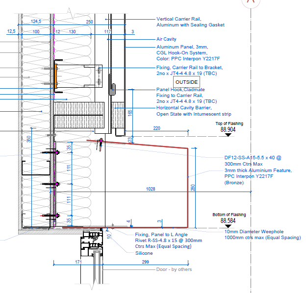
a) VFB-Fire Barrier - Inspection of vertical cavity barriers (FB) FULL FILL CAVITY BARRIER TO SUIT CAVITY,10 mm compression check project spec, x 2 Brackets required per length RV Bracket @ 600 max cc,300 from the edge, x1 Brackets required if the cut length is 300mm or less,x2 Brackets required if the cut length is 301-1200mm, Apply Tape to both sides of the cavity barrier joint The Brackets must penetrate the firestop by 75% at mid-thickness RV Cavity Barriers MUST take priority over RH Intumescent Strip Installed b) HFB-Horizontal cavity barriers - check project spec, 25mm +-3mm GAP,x3 Brackets required per length, nominal 400mm centres, RH Bracket @400 mm cc,x2 Brackets required per length between 100mm and 800mm, Trim split leg to 10-20mm using snips, Apply Tape the top side of the cavity barrier joint, AVOID lengths less than 100mm, Bend split leg in opposing directions using long-nose pliers making sure the bracket is holding the cavity barrier tight but not overly tight, Apply Tape to inside and outside of the RV to RH cavity barrier corner joints around openings. Make sure the cavity barrier is tight around the rail, if there are any gaps, pack with RV/RH offcuts and seal wising Tape. Corner joints should be mitred to ensure a continuous line of intumescent. Additional Intumescent Strip Installed RH25 where the gap is over 25mm. <br> c) Pigtail Screws: The intumescent strip is mechanically fixed to the mineral stone wool by way of pigtail screws minimum of 65mm long applied on-site during installation.<br>
-
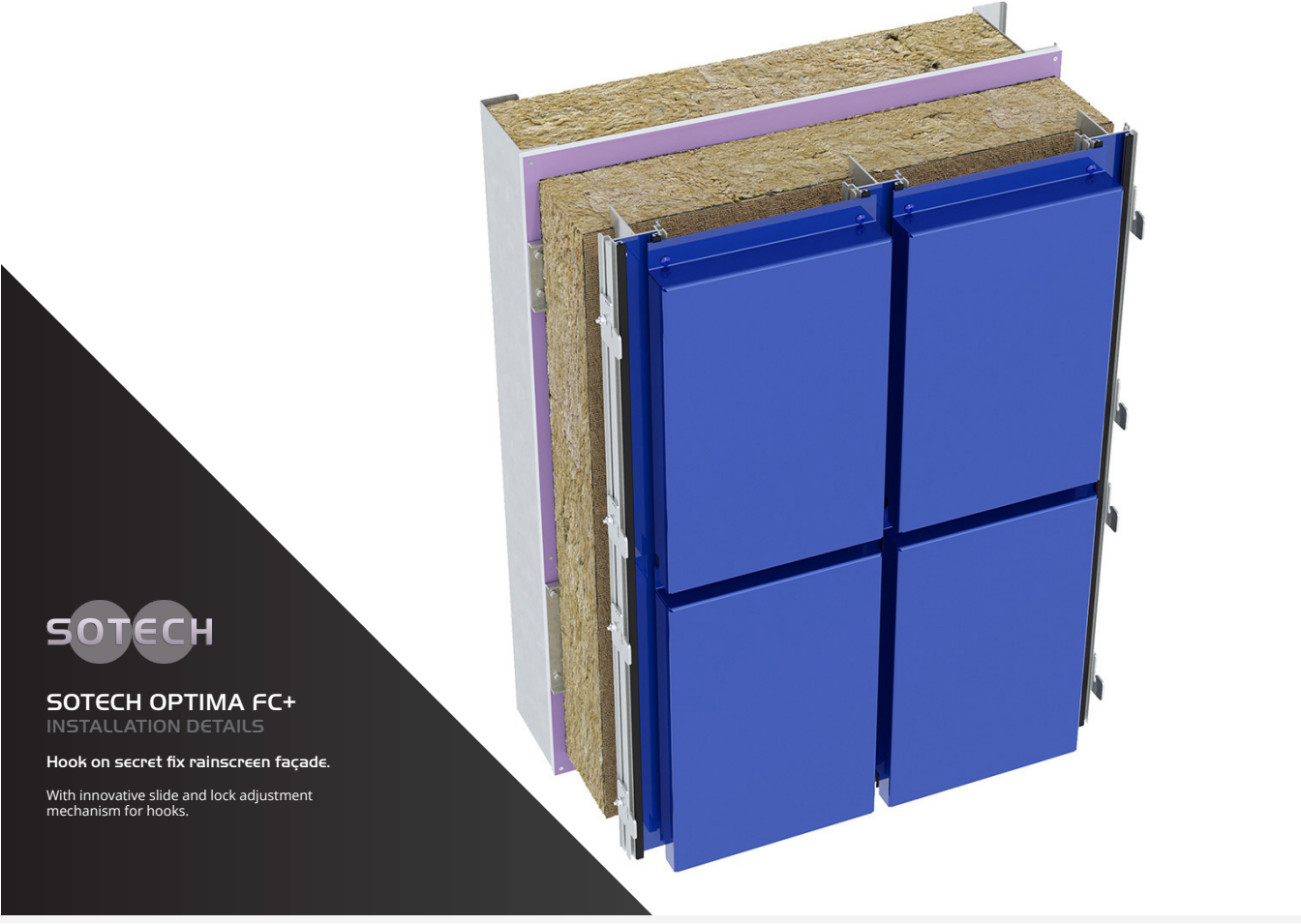
VERTICAL CAVITY BARRIERS<br>SIDERISE RV vertical cavity barriers for rainscreen cladding are used to full fill the void between the external envelope and internal structure.By fully sealing the void, they assist ventilated facades to function by maintaining air-pressurisation compartmentation. Importantly, their unique stonewool lamella core construction enables the vertical barriers to accommodate the sevice ability movement normally associated with rainscreen facades. Intersections between horizontal and vertical cavity barriers are simply abutted.<br>INSTALLATION INSTRUCTIONS<br>•Bend the required SIDERISE Support Bracket on site to give a spike length of 75% of the cavity barrier.<br>•Fix the support brackets to the wall on the centre line of the Vertical barrier location at<br>•600mm Cts & 300mm from each end of each barrier.<br>•Trim Vertical barrier width to give 10mm compression between WD board and rear of the FC+ Panel face.<br>•Line up cavity barrier if the required location and push firmly onto the support brackets ensuring each barrier is tightly abutted to the next to prevent gaps.<br>•All joints to be sealed with Aluminium Foil to to both sides of the Vertical Barrier.
-
HORIZONTAL CAVITY BARRIERS<br>RH ‘Open State’ horizontal cavity barriers have been specifically developed to meet the requirements for cavity barriers used in drained and ventilated facades. Their use ensures that the system will drain any moisture within the facade construction, whilst maintaining airflow and in the event of fire, provide an effective hot smoke and fire seal.<br> Cavity Barrier has developed two ‘Open State’ (open void) horizontal solutions: RH25(G/S) for air gaps up to 25mm and RH50(G/S) for airgaps up to 50mm.<br>The product range is fully compliant to current market requrements and additionally has been tested to recent ASFP Guidance: ‘Open State’ Cavity Barrier used in External Envelope or Fabric of Buildings, utilising principles of EN 1363-1.<br>INSTALLATION INSTRUCTIONS<br>•Trim the rear edge of the horizontal cavity barrier to ensure the correct air gap is achived for the system build-up.<br>•Make small horizontal cuts in the front facing intumescent strip where the ‘split’ fixing brackets are required.<br>•Insert the fixing bracket into the cavity barrier wth the ‘split’ end of the bracket throught the horizontal cuts made in the intumescent strip.<br>•The ‘split’ ends of the brackets should be folded in opposite directions and trimmed to 10-20mm.<br>•Fold the rear side of the bracket to ensure the cavity barrier fits firmly against the WD board when fitted.<br>•Mark out the required position of the horizontal cavity barrier and install with the Siderise logo facing up and tightly abutted to any verical or horizontal cavity barriers to prevent gaps.<br>•Aluminium foil tape or equivalent should be aplied to the top edge of all joints.
-
Cavity Barrier Cassette -OSCI<br>Open State Cassette Inserts (OSCI) are designed for use in Cassette Panel Cladding Systems.<br>•OSCI ‘s can be used horizontally or vertically as part of the cladding system. They are applied directly to the internal surface of the cassette panel to simplify the detailing and installation of adjacent cavity barriers and/or to ensure that the ventilation air gap is dimensioned within the permissible limits.<br>•OSCI’s are positioned parallel and aligned centrally to ‘RH’ or ‘RV’ Cavity Barriers, taking into account the specification of the cladding system assembly. Typically, this requires consideration of the specification and configuration of the cladding panels, the positioning of the support rails or similar steelwork, and/or hook-on or bracket arrangements for panel support.<br>INSTALLATION INSTRUCTIONS<br>•Mark the required position of the OSCI to line up with the coresponding horizontal cavity barrier.<br>•Cut the OSCI(s) to match the internal panel face width at this position.<br>•Cut the ahisive strip on the rear edge of the OSCI 45mm from each side.<br>•Remove the backing film from the adhisive strip leaving the 45mm left by the previous cut.<br>•Compress the edge of the OSCI with the backing fil still in place and puch under the rear return edges.<br>•Ensure the OSCI is in the correct location and firmly push the adhisive to the panel surface.<br>•If required cut out a section of the OSCI to allow for the Vertical cavity barrier
4. Mineral Wool Insulation Installation
-
Rockwool Insulation, fix with Textured outer face of the slab, close edges of the slabs at all vertical and horizontal joints, Stagger the horizontal joints min 100mm, Fixings min 1 no metal and 2 no polypropylene per board, @ max 500 cents, minimum head diameter of 70mm. check project spec
-
MINERAL WOOL INSULATION<br>•Mineral wool insulation is also known as mineral fibre and mineral cotton. Created by spinning or drawing molten or synthetic minerals it’s a fantastic thermal insulator and often has acoustic abilities too.<br>•Our mineral wool system testing category features ROCKWOOL and KNAUF as of the global market leaders in stone wool insulation.<br>INSTALLATION INSTRUCTIONS<br>1.Fit the insulation slabs on top of the horizontal fire barrier ensuring a tight fit between FC+ Carrier rials.<br>2.stack the insulation slab on top of each other in a staggered pattern (or as per the manufactures instructions)<br>3.Sercure the insulation slabs in place using stainless steel fixings and insulation discs, vertically in the centre of each
Hold Point 1: Carrier Rail Installation U & L & T Rails, Fixings, Windows Flashings
- Hold Point 1
-
Hold Point Inspection putting a hold on construction activities until the inspection above is passed. Is a mandatory verification point beyond which a work process cannot proceed without authorisation by the contract administrator. Hold points are usually assigned to those critical aspects of the work that cannot be inspected or corrected at a later stage because they will no longer be accessible.
5. Carrier Rail Installation U & L & T Section
-
RAILS U & L & T- RAILS 65x50x2.2mm & L Section 40x60x2.2mm @ . ALL FIXED BACK TO HELPING HAND BRACKETS AS FOLLOWS: (SUBJECT TO CALCS) SINGLE BRACKET -2 No FX2 THROUGH<br>SLOTTED HOLES (SLIDING FIX) DOUBLE BRACKET - 2 No FX2 THROUGH HOLES (DEAD FIX)
-
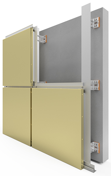
CARRIER RAILS<br>•Carrier rails feature an innovative slide and lock adjustment mechanism, carrier rail hooks can be locked in position on site by installers, or pre-installed in the factory if preferred (see Carrier Assembly Drawing)<br>•Carrier rails will be supplied with gaskets and cover strips pre installed (if required).<br>INSTALLATION INSTRUCTIONS<br>•Make vertical cuts in the horizontal cavity barriers where required to allow the FC+ carrier rail to be inserted.<br>•Line up the carrier rails stem with the spring clamp of the Façade brackets and firmly push the carrier rail into the bracket.<br>•Adjust the locations of the carrier rail vertically to ensure the hooks are in the correct location (the top of the rail will line up with the top of the upstand of the top panel on that rail or the op hook will enamel with the top hook slot of each panel with all lower hooks 5mm lower) using the hook set out edge adjust the horizontal position of the carrier rail to ensure the correct Clad-zone is achieved.<br>•Secure the carrier rail by fixing through the slots/holes in the rainscreen brackets depending on bracket type
6. Windows Flashings & Cills
-
A# Windows Cills & Flashings & Aluminium Cleat Support B# Insect mesh @ Bottom & Top of the Cladding - check project spec C# Aluminium PPC: Jamb Closer, PPC Ventilation, Corner, Drip flashing – project spec
7. Fixings & Carrier Rail Assembly Details
-
Fixings Specification used ,GASKET ,HOOK (PANEL THICKNESS SPECIFIC) M6x20 S/STEEL HEX BOLT ,SPIRALOCK ® M6 HEX FLANGE NUT or check projects spec
HOLD POINT 2: Installation of Cladding and Copings
- 8. Panel Installation
-
Strat Setting Out from Corner & Windows Head & Jamb & Between. Panel Installation is firmly between rails. Ensure perp joints align
-
PANEL SYSTEM<br>•Panels can be quickly and easily fitted top down or bottom up giving a precision fit with 20mm joints horizontally and vertically, with the ability to remove and replace individual panels if required.<br>•Ventilation and Drainage is achieved with the systems specially designed labyrinth joints in the horizontal joints.<br>•The panel system is CWCT & BS8414 accredited.<br>INSTALLATION INSTRUCTIONS<br>•Align the panel centrally between the Carrier rails.<br>•Lift panel into position, inserting the upstand behind the panel above. rotate the bottom of the panel so parallel to the carrier rail liftin the panel up and over the carrier hooks.<br>•Firmly push the panel onto the building to compress the gasket and pull the panel down onto the hooks (ensure the panel fully engages the to hooks for that panel.<br>•Insert the anti lift fixing through the slots in the upstand and into the carrier rail.
9. Movement Joint
-
A# Horizontal Movement Joint as per location/datum/details
-
B# Vertical Movement Joints as per location/datum/details
10. Copings Installation
-
EPDM Membrane installation
-
Aluminium Support BRACKETS Installation ,Line and level the bracket , fixings to spec ,INSTALLATION INSTRUCTIONS
-
Mineral Wool Insulation Installation
11. Other Details or Comments
-
HOLD POINT 3: Handover
- 12 .Handover Inspection
-
Handover Inspection
-
Add signature
