


Title Page
-
ITP No.
-
Principal Contractor / Builder:
-
Project Name:
-
Project Location / Address
-
Conducted on
-
Applicators Name:
-
Location / Area where product is installed:
-
www.constructwaterproofing.com
ABN 71 136 716 366
PH: 0422 102 025
Product Installed
-
Select Membrane Type
- Butynol / PVC / TPO / Ardex1000
- Liquid Applied Membrane
- Spray Applied Membrane
- Torch On Membrane
- Peal & Stick / Self Adhesive Membrane
- Epoxy Sealers / Concrete Sealers
- Vehicle Traffic-able system
- Movement Joint / Construction joint Bandage
- Mainterance waterproofing
Liquid Membranes
-
Product Name:
- Sika 488
- Ardex 002
- Grace Aquagard M
- Grace Aquagard M Non-Slip Topcoat
- Grace Newflex R100
- Grace Ultraure A-80 Membrane
- Grace Newflex WAM Fibre Grey
- Grace Tuffcote Duratop
- Grace Fastflex
- Tremco Vulkem Non-Exposed Membrane (N.E.M.)
- Pasco Aquaproof 110
- Pasco Aquaproof 115
- Pasco Aquaproof SLM
- Tremco Eco NEM
- TREMproof® 60
- TREMproof® 90
- Tremco TREMproof 120
- Vulkem® 350-R NF
- Tremco Tremproof 350 SL
- Tremco Tremproof 351
- Vulkem® 360NF
- Vulkem® 951NF
- Tremco TREMproof® 250GC
- Ardex WPM 157 membrane
- Ardex WPM 908
- Ardex WPM 155
- Ardex WPM 179
- Ardex WPM 300
- Grace Epocote F100W HD
- Grace Epocote F100 Grey
- Grace Epocote F100 Clear
- Grace Ultraure A80 Top Coat
- Alsan Flashing
- Brushable Hydroseal
- Parchem Vandex BB75
- Other:
-
Primer Applied:
-
Primer Application Dates:
-
Primer batch numbers
-
Membrane Application Dates:
-
Membrane batch numbers
-
Wet Film Thickness
-
Dry Film Thickness
1. Product has been checked against the Applicators copy of Quoted works, and the marked up plans:
-
Does the product delivered to site match the Applicator's copy, and the nominated location on the marked up plans? <br>Does the membrane and membrane application follow the suppliers specifications? Also the Construct Applicator has read and understood the Technical Data Sheet for the product, provided in the Construct Site Folder.
2. Acceptance of Substrate -
-
The substrate has been prepared by Buildier/Client. All falls of substrate has signed off by builder/ Client.<br>a) Moisture Content Accepted - equal or less than 6% or suitable for the membrane applied as per Supplier TDS.<br>b) Correct Drain waste Details Accepted by Builder/Client <br>c) Substrate has acceptable Smoothness and Uniformity for application of Membrane<br>e) Screed Substrate is acceptable for application of Membrane<br>f) Substrate is suitably clean for application of Membrane
List the issues relating to the substrate:
-
Does this relate to any of the following items:
- Curingtimes & Moisture Content of Concrete
- Contaminants and issues affecting bonding
- Caulking not compatible - Silicon etc installed by other trades
- Fire Caulking
- Substrate finish suitable for membrane - Concrete
- Substrate finish suitable for membrane - Blockwork
- Substrate finish suitable for membrane - Lightweight Timber structures
- Post Tension Pockets, Grout Tubes etc
- Work area not clean and clear of any building Debris, ponding water, Other Trades, other items
- Exclusion / Drop Zone
- Weather - Rain and Temperature
- Hobs and Up-turn heights
- Falls / Drainage
- Floor Wastes
- Pipe Penetrations
- Flexible Conduits
- Bunched Pipes / Conduits
- Overflows
- Fixings & Penetrations through the membrane
- Dividing Walls, Landscape Walls, Retaining walls - ontop of membranes
- Construction Joints
- Handrails
- Screed MPA / strength
- Protection not installed over membrane - ie protection board under drainage cell and soil etc
- Pipes hard against walls and hobs - not able to properly detail
- Other Finishes already installed
- Damage done to membrane
- Other items
-
Curing times of substrates:
All concrete and masonry should be cured for 28 days prior to application of the membrane - as per supplier’s requirements on their Technical Data Sheets to meet warranty conditions.
AS 4654.2 – 2012 states:
“moisture content in the substrate should be under 8.0% for most membranes (5% or less for Spray applied Polyurea membranes). If a Waterproof membrane is applied to a damp/green substrate there is a high risk the application will either de-bond or become fractured due to the force of the moisture trying to evaporate from the substrate. When there is trapped moisture in the substrate membranes can show signs of blistering or bubbling known in the industry pin holing, and delamination.” -
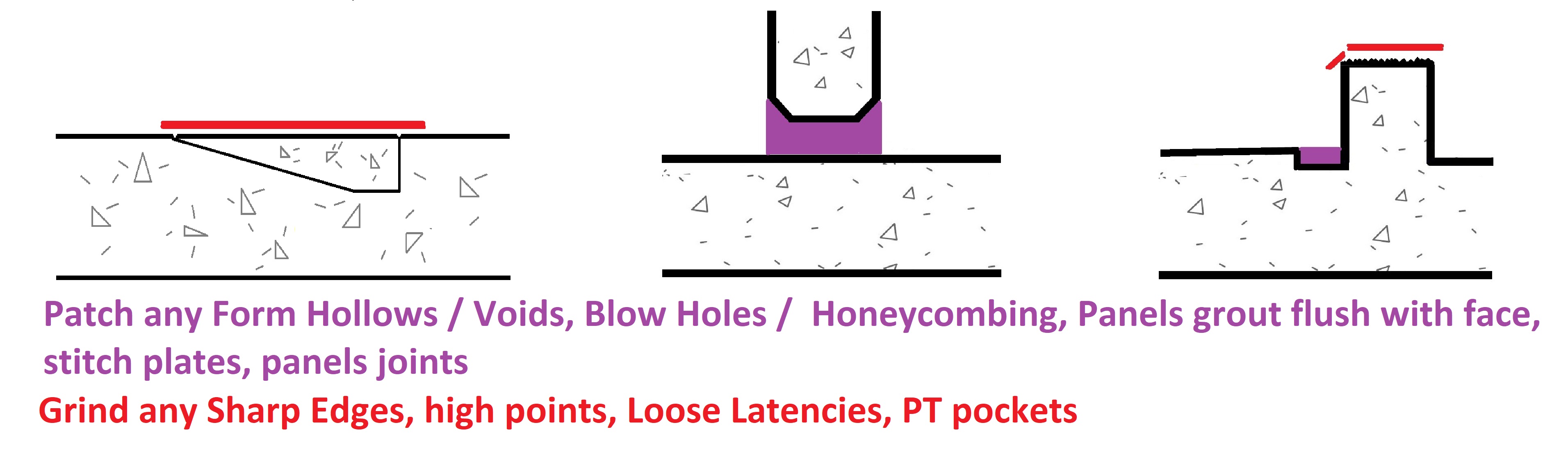
Substrate surface patching / preparation required prior to membrane application.
To be done by others.
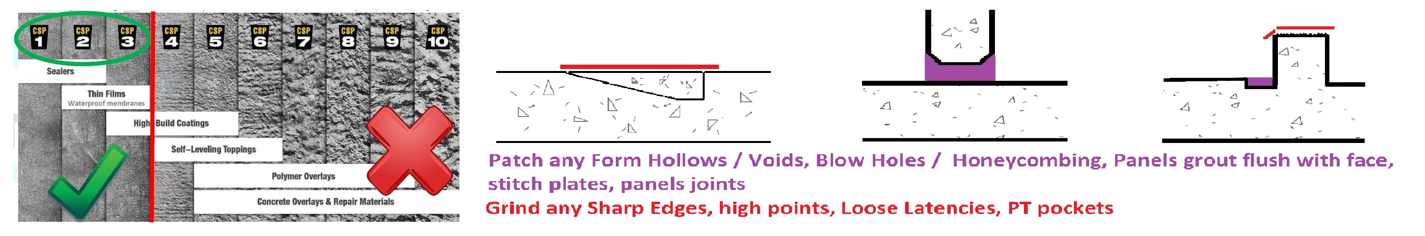
AS 4654.2—2012 states "The substrate shall be smooth, without protrusions, voids or formwork distortions, and clean, dry, and free from dust and contamination."
Finish compatible with membrane, generally not rougher than a wood trowel/float or broom finish concrete, approximately CSP3.
There should be no blow holes / bug holes in the substrate.
Grinding and patching requirements:
To be done by others prior to membrane application. all patching products must be properly cured (3 days) before membrane application. -
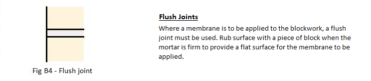
Blockwork:
Mortar in block work needs to be a flush joint, smooth and level with the blocks, no blow outs of mortar.
No Versaloc, or similar block work wall systems for membranes, as there are gaps in the block work which will become a weak point in the membrane.
AS 4654.2—2012 states "The substrate shall be smooth, without protrusions, voids or formwork distortions, and clean, dry, and free from dust and contamination." -
Lightweight Structures:
Framing supports at a maximum 400mm centres (in one direction). All CFC or plywood sheet edges must also be supported. Do not use tongue and groove plywood. If thicker plywood is to be used support spacing needs to meet AS 1684 for Residential Timber Framed Construction, AS1860 and structural plywood which must comply with AS/NZS 2269.
o Tongue & Groove strip timber floors are not acceptable wet area substrates under
these requirements.
o NOTE: For further information on suitability of materials used for substrates, refer to
the following:
a. Timber, AS 1684 (all parts).
b. Plywood, AS/NZS 2269.
c. Cellulose-cement products, AS/NZS 2908.2 or ISO 8336.
Minimum 19mm treated structural plywood H4 grade or 19mm Compressed Fibre Cement
sheet.
Minimum CD grade with the sanded C face upwards.
Plywood laid with face grain at right angles to supports.
Plywood is to be laid with staggered joints in a brick bond pattern with a 3mm expansion gap
between plywood sheet edges. Bond breaker tape to be applied to all plywood sheet joints
prior to membrane application (Liquid membranes only).
Plywood is screwed with 10g x 50mm SS counter sunk screws at 150mm centres on all sheet
edges and at 200mm centres through the body of the sheet. All screws to be counter sunk 1-
2mm.
Provide 20mm timber fillets at the base of all upstands.
Chamfer all external edges with a minimum radius of 5mm.
Plywood is to be kept dry at all times during construction. Blow/ torch drying the plywood
surface prior to membrane application does not comply. Plywood and framing supports to
be at no more than 5% moisture content.
For Roofs and Roof Decks over living spaces, all cavities must be ventilated and insulated in
compliance with the Building Code of Australia (BCA).
All drains and outlets are membrane compatible. -
Work area not Clear:
Building Debris, Ponding water, Other trades working in area, and other items found in area preventing membrane works able to be installed. These need to be removed prior to the membrane application.
Removal to be done by others, either the trade responsible or the builder. -
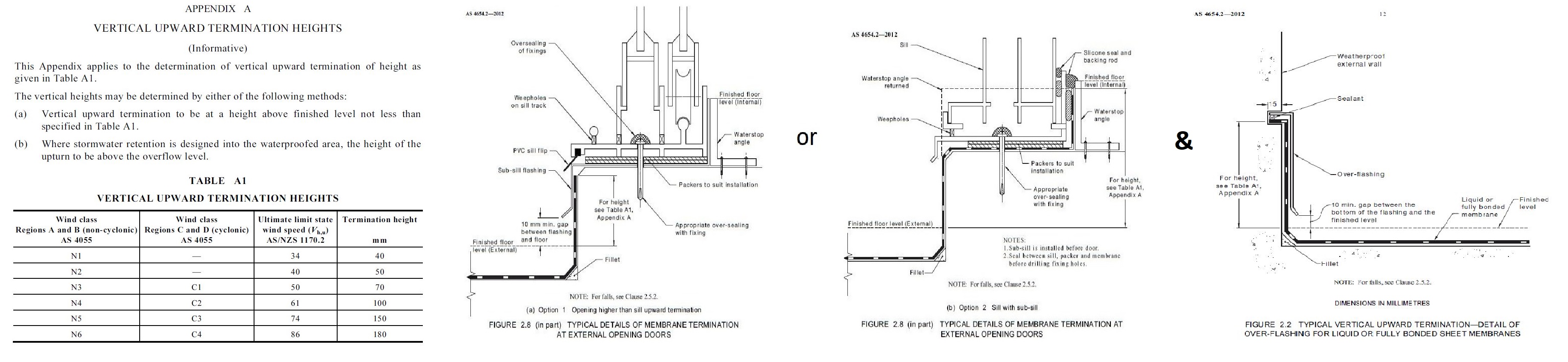
Correction of Hobs required.
AS 4654.2 – 2012 – 2.8.3 states Door and Window hobs should be as follows:
- “Typical details of external terminations at external opening doors and at wall openings are shown in Figure 2.8 and Figure 2.9.”
- “Openings should be provided with a set-down or hob to provide a vertical surface of sufficient dimension. See also Table A1, Appendix A.” Membrane upturn height must be equal to or greater than the height determined in Table A1, Appendix A. And is determined from the top of the floor finished surface level, which includes membrane termination above pavers on pods.
- “Sub-sill flashing shall be included as part of the membrane system”
Correction of Upturn heights required to allow the membrane to finish above the floor finish surface, including pavers on pods.
AS 4654.2 – 2012 - 2.8.1.1 Height, states that:
“Where the membrane termination is to prevent water entry, the finished height of the membrane above the finished surface level shall be sufficient to prevent water, including wind driven, flowing over the top of the membrane."
The vertical heights may be determined by either of the following methods:
(a) Vertical upward termination to be at a height above finished level not less than specified in Table A1.
(b) Where stormwater retention is designed into the waterproofed area, the height of the upturn to be above the overflow level. -
Correction of Falls / drainage required.
AS 4654.2 – 2012 – 2.5.2 states:
“Falls in finishes shall ensure water drains to the drainage outlet. Water shall not be retained on the finished surface with the exception of residual water remaining due to surface tension. The fall shall be in the structural substrate, or formed by a screed over the structural substrate. NOTE: Falls for surface drainage should be no flatter than 1 in 100.” -
Correction of floor wastes / drainage required. The floor waste must be connected prior to membrane application to allow the water to drain away. Also the flange on the floor waste needs to be exposed to allow bonding of the membrane onto the flange.
AS 4654.2 – 2012 – 2.5.2 states:
“The membrane shall be connected to the stormwater drainage system through a turn down of the membrane into the inlet of the system as shown in Figure 2.15. An alternative connection may have a flange to which the membrane is clamped or attached" -
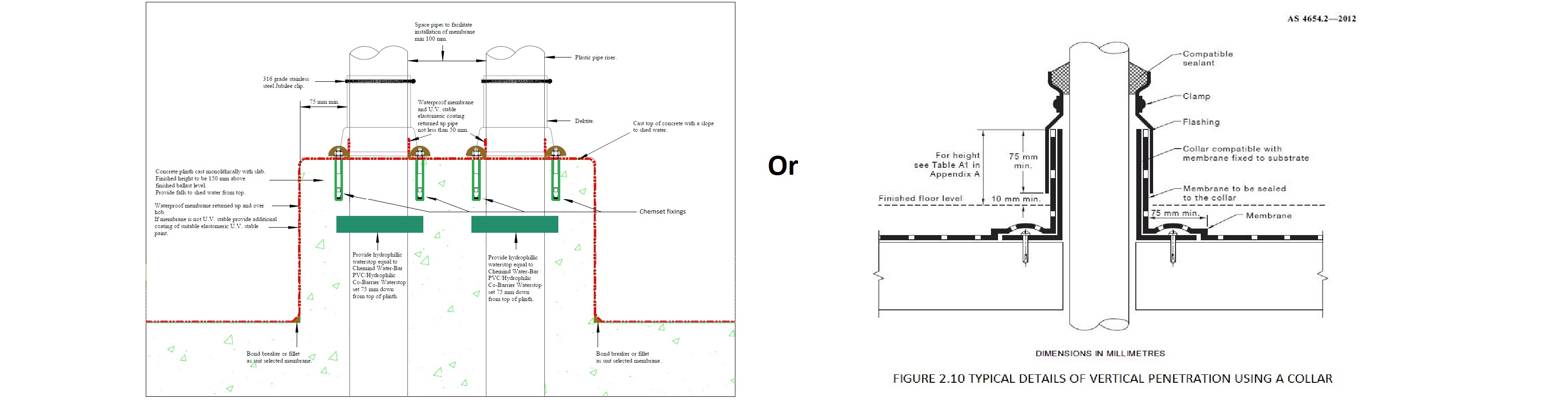
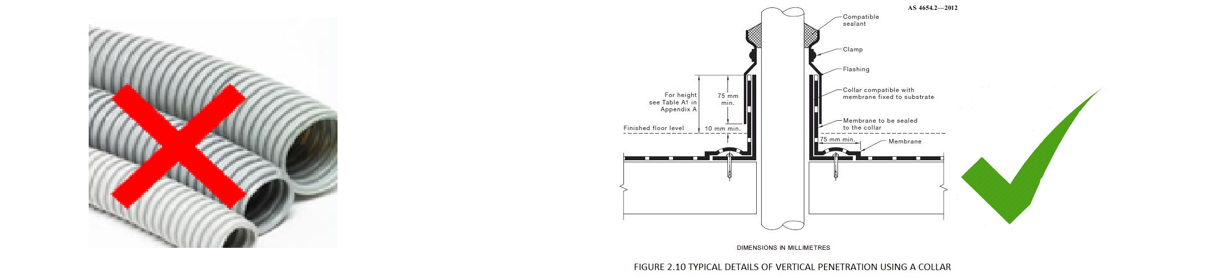
Penetrating the membrane should be avoided at all times where possible, as this is one of the most common causes of water ingression.
AS 4654.2 – 2012 – 2.5.2 states:
“All pipes, ducts and vents should be located within a collar mechanically fixed to the substrate as an extension to the penetration. Alternatively, a collar may be cast into the substrate to form the penetration. A separate collar should be used for each penetration.” & “all penetrations should be packed to stabilize the pipe”
Other contractors should avoid penetrating slabs wherever possible, but where penetrations are essential they must be detailed correctly:
1. Properly secured with flanged sleeves and clamp collars.
a. a separate collar must be used for each penetration, either cast in, or mechanically fixed.
2. Where they occur through a slab, plinths to be poured around them to raise the critical tear point away from potential ponding water
3. Penetration not located next to a floor waste or critical point,
a. ie the floor wall junction
4. Singular (not bunched together) to allow correct detail to occur around each penetration.
5. No flexible corrugated conduit – it always breaks.
6. Use hydrophilic wraps and seals when casting into the slab.
7. No Voids around penetrations. All properly patched.
8. No HDPE pipes installed where the membrane will connect onto the HDPE.
a. If HDPE is required it must be sleeved with a collar that allows bonding of the membrane to occur. -
Flexible conduits must be avoided anywhere you expect to get water. They are made from thinner gauge materials, cannot be properly secured which results in breaking from movement, and usually also break the waterproofing detail. Penetrating the membrane should be avoided at all times where possible, as this is one of the most common causes of water ingression.
AS 4654.2 – 2012 – 2.5.2 states:
“All pipes, ducts and vents should be located within a collar mechanically fixed to the substrate as an extension to the penetration. Alternatively, a collar may be cast into the substrate to form the penetration. A separate collar should be used for each penetration.” & “all penetrations should be packed to stabilize the pipe” -
Bunched pipes are impossible to detail correctly and not compliant with AS4564.2. The preferred Penetration detail:
- All Pipe penetrations have a plinth installed around them.
- Pipes are individually spaced out and not bunched together.
AS 4654.2 – 2012 – 2.5.2 states:
“All pipes, ducts and vents should be located within a collar mechanically fixed to the substrate as an extension to the penetration. Alternatively, a collar may be cast into the substrate to form the penetration. A separate collar should be used for each penetration.” & “all penetrations should be packed to stabilize the pipe” -
Penetrating the membrane should be avoided at all times where possible, as this is one of the most common causes of water ingression.
Other contractors should avoid penetrating slabs wherever possible, but where penetrations are essential they must be detailed correctly by 2 part epoxy injection to set them in place.
AS 4654.2 – 2012 states that any fixings, threaded rods, starter bars, and bolts should be 2 part epoxy injection set in place to reduce water ingression:
“All penetrations into concrete should be treated with epoxy. All fixings into concrete should be of a chemically injected type in order to maintain the integrity of the waterproofing and substrate.”
Process for 2 part epoxy injection fixings:
1. Overfill holes with 2 part epoxy injection.
2. Blow out dust to make sure adequate bond occurs.
3. Turn Bars clockwise with the thread to avoid any air bubbles occurring in the mix and bonds onto the entire thread.
4. Make sure mix overflows out of the hole.
5. Smooth out 2 part epoxy injection around bars -
Overflows need to be correctly installed prior to the membrane application.
AS 4654.2 – 2012 – 2.11 states:
“The membrane shall be turned into the overflow, to prevent moisture from tracking behind the membrane. The finished floor level shall not reduce the design flow of an outlet. NOTES: 1 Typical examples of membranes turned into the overflow are shown in Figure 2.16."
All Overflows through walls should be cored on a downward angle away from the area.
Must have preformed outlets installed prior to membrane application. -
Dividing walls - Must allow sequencing to occur for all walls being installed over a membrane:
- Membrane installed onto substrate.
- Bars installed and properly 2 part Epoxy / Chemset, please see notes on Chemset.
- Walls then installed
- If block walls being installed, then:
- Flush mortar joints for section to receive membrane.
- Tops of walls must be steel trowel to smooth core fill
- No voids, blowholes, bug holes, form-work distortions -
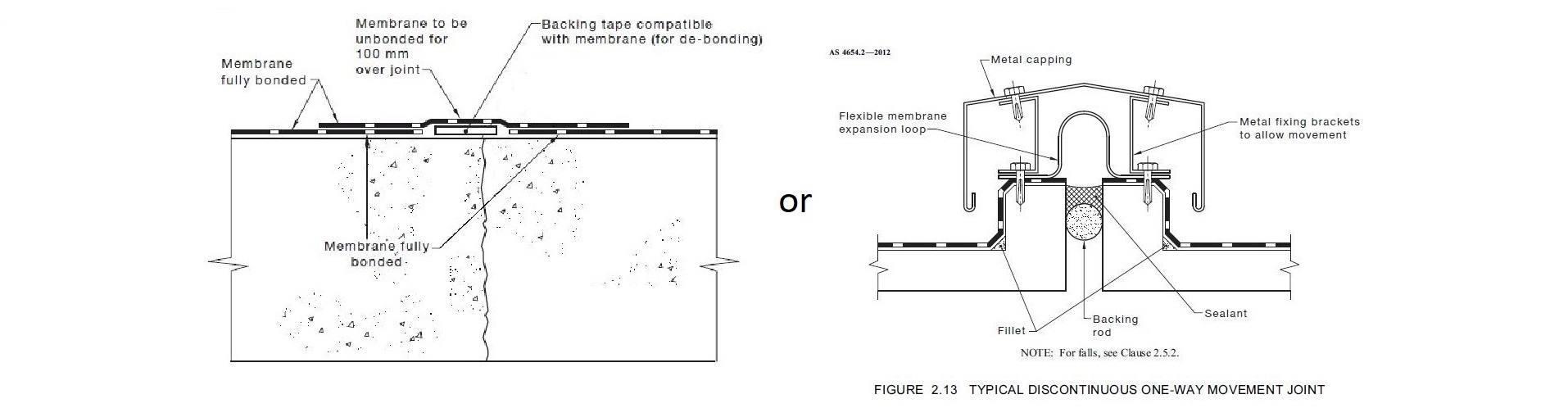
Movement joints and Construction joints should be avoided in high risk locations where water may be constantly present, i.e. through planter boxes etc.
i. Identify where these will occur and quantum of movement is nominated, co-ordinate to reduce risks of failure in the design phase.
AS 4654.2 – 2012 states
“Where a building or structure has construction joints, movement joints or control joints, the membrane shall be either discontinuous or continuous over the joint, to allow for the anticipated movement. Where continuous, the membrane shall be unbonded for the first 100 mm. NOTES: Typical detail of a discontinuous membrane over the joint is shown in Figure 2.13."
2. Typical detail of a continuous membrane over the joint is shown in Figure 2.14. “ -
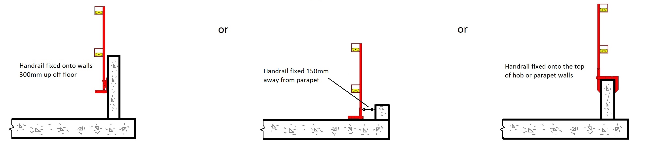
Safety handrails need to be correctly installed above the height of the membrane. Either up on top of the hob or onto the face of the wall / parapet.
It is critical the handrail is not placed onto the floor wall junction, the most critical point, as this will create a weak point in the membrane detail. There must be a 200mm space between the upturn junction and the handrail fixing to allow for a continuous bead of caulk and membrane detail. -
Contaminants cause issues with membrane adhesion to the substrate. All contamination such as oils, rubber from tyre treads etc must be removed prior to application of any membrane. Any installed products must be checked for adhesion compatibility prior to ensure the membrane can be warranted with each item.
-
Where a membrane is to be installed over a screed, the screed needs to achieve a compressive strength of 20 Mpa and tensile strength of 1.5 Mpa to be considered acceptable as required under the Australian Standards AS1884 – 2012 & AS3958.1. Please provide evidence that this has been achieved.
-
All caulking by other trades must be compatible with the membrane being installed.
If a polyurethane, Polyurea, Acrylic, and Cementitious membrane is being installed, the caulking product must be a neutral cure polyurethane caulk.
If a Bituminous sheet or Liquid membrane is being installed a Bituminous impregnated caulk must be used.
NO Silicon caulking is compatible with membranes. It is a cause of debonding and delamination issues. -
An Acrylic Fire caulk has been noted in this area. Please note most Fire caulking is not compatible with membranes and is not suitable for external use. This is because Acrylic fire caulks have a propensity to shrink and distort over time, also emulsify when wet.
All caulking by other trades must be compatible with the membrane being installed.
If a polyurethane, Polyurea, Acrylic, and Cementitious membrane is being installed, the caulking product must be a neutral cure polyurethane caulk.
If a Bituminous sheet or Liquid membrane is being installed a Bituminous impregnated caulk must be used. -
AS 4654.2 – 2012 states that “Where a membrane is to be overlayed with another system (e.g. ballast, insulation, soil and the like), the overlaying system shall be compatible with, and not cause damage to, the membrane. & a slip sheet or protection board may be required and not cause damage to, the membrane. & a slip sheet or protection board may be required between the membrane and the overlaying surface "
-
Do not locate the penetrating element hard to the floor and wall junction. This is an impossible detail to make 100% watertight, as there is always a section that cannot be detailed properly, refer picture on right. Make sure there is a minimum of 50-100mm space between the penetration and the wall or floor to allow for proper detailing of the membrane.
-
undefined
-
Post Tension Pockets, Grout Tubes etc: Substrate surface patching / preparation required prior to membrane application.
To be done by others.
AS 4654.2—2012 states "The substrate shall be smooth, without protrusions, voids or formwork distortions, and clean, dry, and free from dust and contamination."
Finish compatible with membrane, generally not rougher than a wood trowel/float or broom finish concrete, approximately CSP3.
There should be no blow holes / bug holes in the substrate.
Grinding and patching requirements:
To be done by others prior to membrane application. all patching products must be properly cured (3 days) before membrane application. -
Drop Zone / Exclusion zone in Work area:<br>Other trades working in area above preventing membrane works able to be installed. Site Foreman to co-ordinate this area to be free from other trades to allow membrane works to be completed.
-
Weather – Rain and temperature:
Where weather conditions are not compliant with Supplier T.D.S. requirement for installation of membranes. The following conditions prohibit membrane application to occur:
a) Ambient temperature - between 5°C and 35°C.
b) Do not apply materials during conditions of rain, mist, fog or snow.
c) Ensure rain is not forecast during the application process or less than 4 hours following. -
Other Finishes already installed:
Other finishes cause issues with membrane adhesion to the substrate and cannot be guaranteed. All installed finishes such as paints, renders, tiles etc must be removed prior to application of any membrane. Any installed products must be checked for adhesion compatibility prior to ensure the membrane can be warranted with each item. -
Damage done to Membrane:
Damage has occurred to membrane after installation. All repairs to be done on hours and materials as a variation. -
Was this reported to the builder's Foremen or Supervisors?
-
Name of Person reported to:
-
Reason why installation of Membrane continued even though substrate had the above issues:


3. Clean and prepare substrate - AS 4654 .2.2012 Section 2.5
-
The Construct applicator has performed the following:<br>a) A scrape, stiff brush, or light grind of the area prior to product installation.<br>b) Ensure all surfaces are structurally sound or securely fixed and totally dry. The surface to be coated should be free from dust, oil, curing compounds or any other contaminating materials. I
4. Application of primer to prepare surface for adhesion of membrane:
-
The Construct Applicator has read and understood the Technical Data Sheet for the product, provided in the Construct Site Folder.<br>The entire surface to receive the membrane has had the relevant primer installed, including turn-ups, using brush or roller as specified in the Technical Data Sheet.<br>Allowed the area primed to properly dried and cured prior to membrane application. Correct curing time and number of coats as specified in the Technical Data Sheet.<br>
5. Fillets / Caulking - A cove or curved profile used at internal intersections to assist the membrane to accommodate the transition from horizontal to vertical surfaces.
-
The Construct applicator has ensured fillets/caulking has been applied and smoothed off to all internal intersections. Corners to be rounded and smoothed to an adequate width, ensuring depth is not greater than width.
6. Application of first layer / coat of membrane AS 4654 .2.2012 Section 2.6
-
The Construct applicator has read and understood the Technical Data Sheet for the product, provided in the CW Site Folder.<br>Ensuring the turn ups the correct height as specified in the Technical Data Sheet, project drawings(eg. AS.150mm minimum).<br>Applied liquid membranes with a roller/squeegee to the correct wet film thickness as specified in the Technical Data Sheet, and allowed required curing times.
-
The completed membrane is free from Pinholes & Irregularities <br>The membrane has the correct adhesion/bonding to the substrate, correct smoothness and uniformity and is continuous across the extent of the substrate. <br>If no, state actions required
-
Construction Joints and Penetrations.<br>The applicator has installed the correct detailing and material to allow for Fixing and Supports (Detailing)<br>
-
Wet Film Thickness:
7. Application of second layer of membrane if required
-
The Construct applicator has read and understood the Technical Data Sheet for the product, provided in the Construct Site Folder.<br>Ensuring the turn ups the correct height as specified in the Technical Data Sheet, project drawings(eg. AS. 150mm minimum).<br>Applied liquid membranes with a roller/squeegee to the correct wet film thickness as specified in the Technical Data Sheet, and allowed required curing times.
8. Pictures of Area that was installed / inspected:
-
Pictures of area:
-
Pictures of Penetrations in membrane:
-
Pictures of Perimeter detailing, ie: membrane turn-up of 150mm minimum
-
Any Notes / Comments / Issues:
-
To be used for multiple locations on site:
Inspected and approved by Construct
-
Signature of Construct applicator:
Inspected and Approved by Head Contractor
-
Signature of Builder / client Site Manager / Foreman:
Third Party Inspection
-
undefined
Water Tested
-
-
Water test Date
Spray Applied Membrane
-
Product name:
- Grace Chemspray 790 - Polyurea Membrane
- Grace Chemspray UV Trafficable Topcoat
- Rhino PP1195 Pure Polyures
- Enviro HP 1200
- Enviro 800 PUR or 900PUR
- Fasteflex to tops of walls
- Other:
-
Name / Description of product installed:
-
Number of Kits installed?
-
Product Batch Number:
-
Photo of Batch Number:
1. Product has been checked against the Applicators copy of Quoted works, and the marked up plans, and product TDS read:
-
Product is suitable for location as per AS 4654.1.2012
-
Does the product delivered to site match the Applicator's copy, and the nominated location on the marked up plans?<br>Also the Watertite Applicator has read and understood the Technical Data Sheet for the product, provided in the Watertite Site Folder.
2. Acceptance of Substrate - AS 4654 .2.2012 Section 2.5
-
The area has been inspected and accepted for the following where relevant and applicable to AS 4654 .2.2012 Section 2.5:<br>a) Moisture Content Accepted - equal or less than 5% or suitable for the membrane applied as per Supplier TDS.<br>b) Condition of Substrate Accepted as relevant to the Suppliers TDS<br>c) Correct Drain waste Details Accepted<br>d) Substrate has acceptable Smoothness and Uniformity for application of Membrane<br>e) Screed Substrate is acceptable for application of Membrane<br>f) Substrate is suitably clean for application of Membrane
List the issues relating to the substrate:
-
Does this relate to any of the following items:
- Curingtimes & Moisture Content of Concrete
- Contaminants and issues affecting bonding
- Caulking not compatible - Silicon etc installed by other trades
- Fire Caulking
- Substrate finish suitable for membrane - Concrete
- Substrate finish suitable for membrane - Blockwork
- Substrate finish suitable for membrane - Lightweight Timber structures
- Post Tension Pockets, Grout Tubes etc
- Work area not clean and clear of any building Debris, ponding water, Other Trades, other items
- Exclusion / Drop Zone
- Weather - Rain and Temperature
- Hobs and Up-turn heights
- Falls / Drainage
- Floor Wastes
- Pipe Penetrations
- Flexible Conduits
- Bunched Pipes / Conduits
- Overflows
- Fixings & Penetrations through the membrane
- Dividing Walls, Landscape Walls, Retaining walls - ontop of membranes
- Construction Joints
- Handrails
- Screed MPA / strength
- Protection not installed over membrane - ie protection board under drainage cell and soil etc
- Pipes hard against walls and hobs - not able to properly detail
- Other Finishes already installed
- Damage done to membrane
- Other items
-
Curing times of substrates:
All concrete and masonry should be cured for 28 days prior to application of the membrane - as per supplier’s requirements on their Technical Data Sheets to meet warranty conditions.
AS 4654.2 – 2012 states:
“moisture content in the substrate should be under 8.0% for most membranes (5% or less for Spray applied Polyurea membranes). If a Waterproof membrane is applied to a damp/green substrate there is a high risk the application will either de-bond or become fractured due to the force of the moisture trying to evaporate from the substrate. When there is trapped moisture in the substrate membranes can show signs of blistering or bubbling known in the industry pin holing, and delamination.” -
Substrate surface patching / preparation required prior to membrane application.
To be done by others.
AS 4654.2—2012 states "The substrate shall be smooth, without protrusions, voids or formwork distortions, and clean, dry, and free from dust and contamination."
Finish compatible with membrane, generally not rougher than a wood trowel/float or broom finish concrete, approximately CSP3.
There should be no blow holes / bug holes in the substrate.
Grinding and patching requirements:
To be done by others prior to membrane application. all patching products must be properly cured (3 days) before membrane application. -
Blockwork:
Mortar in block work needs to be a flush joint, smooth and level with the blocks, no blow outs of mortar.
No Versaloc, or similar block work wall systems for membranes, as there are gaps in the block work which will become a weak point in the membrane.
AS 4654.2—2012 states "The substrate shall be smooth, without protrusions, voids or formwork distortions, and clean, dry, and free from dust and contamination." -
Lightweight Structures:
Framing supports at a maximum 400mm centres (in one direction). All CFC or plywood sheet edges must also be supported. Do not use tongue and groove plywood. If thicker plywood is to be used support spacing needs to meet AS 1684 for Residential Timber Framed Construction, AS1860 and structural plywood which must comply with AS/NZS 2269.
o Tongue & Groove strip timber floors are not acceptable wet area substrates under
these requirements.
o NOTE: For further information on suitability of materials used for substrates, refer to
the following:
a. Timber, AS 1684 (all parts).
b. Plywood, AS/NZS 2269.
c. Cellulose-cement products, AS/NZS 2908.2 or ISO 8336.
Minimum 19mm treated structural plywood H4 grade or 19mm Compressed Fibre Cement
sheet.
Minimum CD grade with the sanded C face upwards.
Plywood laid with face grain at right angles to supports.
Plywood is to be laid with staggered joints in a brick bond pattern with a 3mm expansion gap
between plywood sheet edges. Bond breaker tape to be applied to all plywood sheet joints
prior to membrane application (Liquid membranes only).
Plywood is screwed with 10g x 50mm SS counter sunk screws at 150mm centres on all sheet
edges and at 200mm centres through the body of the sheet. All screws to be counter sunk 1-
2mm.
Provide 20mm timber fillets at the base of all upstands.
Chamfer all external edges with a minimum radius of 5mm.
Plywood is to be kept dry at all times during construction. Blow/ torch drying the plywood
surface prior to membrane application does not comply. Plywood and framing supports to
be at no more than 5% moisture content.
For Roofs and Roof Decks over living spaces, all cavities must be ventilated and insulated in
compliance with the Building Code of Australia (BCA).
All drains and outlets are membrane compatible. -
Work area not Clear:
Building Debris, Ponding water, and other items found in area preventing membrane works able to be installed. These need to be removed prior to the membrane application.
Removal to be done by others, either the trade responsible or the builder. -
Correction of Hobs required.
AS 4654.2 – 2012 – 2.8.3 states Door and Window hobs should be as follows:
- “Typical details of external terminations at external opening doors and at wall openings are shown in Figure 2.8 and Figure 2.9.”
- “Openings should be provided with a set-down or hob to provide a vertical surface of sufficient dimension. See also Table A1, Appendix A.” Membrane upturn height must be equal to or greater than the height determined in Table A1, Appendix A. And is determined from the top of the floor finished surface level, which includes membrane termination above pavers on pods.
- “Sub-sill flashing shall be included as part of the membrane system”
Correction of Upturn heights required to allow the membrane to finish above the floor finish surface, including pavers on pods.
AS 4654.2 – 2012 - 2.8.1.1 Height, states that:
“Where the membrane termination is to prevent water entry, the finished height of the membrane above the finished surface level shall be sufficient to prevent water, including wind driven, flowing over the top of the membrane."
The vertical heights may be determined by either of the following methods:
(a) Vertical upward termination to be at a height above finished level not less than specified in Table A1.
(b) Where stormwater retention is designed into the waterproofed area, the height of the upturn to be above the overflow level. -
Correction of Falls / drainage required.
AS 4654.2 – 2012 – 2.5.2 states:
“Falls in finishes shall ensure water drains to the drainage outlet. Water shall not be retained on the finished surface with the exception of residual water remaining due to surface tension. The fall shall be in the structural substrate, or formed by a screed over the structural substrate. NOTE: Falls for surface drainage should be no flatter than 1 in 100.” -
Correction of floor wastes / drainage required. The floor waste must be connected prior to membrane application to allow the water to drain away. Also the flange on the floor waste needs to be exposed to allow bonding of the membrane onto the flange.
AS 4654.2 – 2012 – 2.5.2 states:
“The membrane shall be connected to the stormwater drainage system through a turn down of the membrane into the inlet of the system as shown in Figure 2.15. An alternative connection may have a flange to which the membrane is clamped or attached" -
Penetrating the membrane should be avoided at all times where possible, as this is one of the most common causes of water ingression.
AS 4654.2 – 2012 – 2.5.2 states:
“All pipes, ducts and vents should be located within a collar mechanically fixed to the substrate as an extension to the penetration. Alternatively, a collar may be cast into the substrate to form the penetration. A separate collar should be used for each penetration.” & “all penetrations should be packed to stabilize the pipe”
Other contractors should avoid penetrating slabs wherever possible, but where penetrations are essential they must be detailed correctly:
1. Properly secured with flanged sleeves and clamp collars.
a. a separate collar must be used for each penetration, either cast in, or mechanically fixed.
2. Where they occur through a slab, plinths to be poured around them to raise the critical tear point away from potential ponding water
3. Penetration not located next to a floor waste or critical point,
a. ie the floor wall junction
4. Singular (not bunched together) to allow correct detail to occur around each penetration.
5. No flexible corrugated conduit – it always breaks.
6. Use hydrophilic wraps and seals when casting into the slab.
7. No Voids around penetrations. All properly patched.
8. No HDPE pipes installed where the membrane will connect onto the HDPE.
a. If HDPE is required it must be sleeved with a collar that allows bonding of the membrane to occur. -
Flexible conduits must be avoided anywhere you expect to get water. They are made from thinner gauge materials, cannot be properly secured which results in breaking from movement, and usually also break the waterproofing detail. Penetrating the membrane should be avoided at all times where possible, as this is one of the most common causes of water ingression.
AS 4654.2 – 2012 – 2.5.2 states:
“All pipes, ducts and vents should be located within a collar mechanically fixed to the substrate as an extension to the penetration. Alternatively, a collar may be cast into the substrate to form the penetration. A separate collar should be used for each penetration.” & “all penetrations should be packed to stabilize the pipe” -
Bunched pipes are impossible to detail correctly and not compliant with AS4564.2. The preferred Penetration detail:
- All Pipe penetrations have a plinth installed around them.
- Pipes are individually spaced out and not bunched together.
AS 4654.2 – 2012 – 2.5.2 states:
“All pipes, ducts and vents should be located within a collar mechanically fixed to the substrate as an extension to the penetration. Alternatively, a collar may be cast into the substrate to form the penetration. A separate collar should be used for each penetration.” & “all penetrations should be packed to stabilize the pipe” -
Penetrating the membrane should be avoided at all times where possible, as this is one of the most common causes of water ingression.
Other contractors should avoid penetrating slabs wherever possible, but where penetrations are essential they must be detailed correctly by 2 part epoxy injection to set them in place.
AS 4654.2 – 2012 states that any fixings, threaded rods, starter bars, and bolts should be 2 part epoxy injection set in place to reduce water ingression:
“All penetrations into concrete should be treated with epoxy. All fixings into concrete should be of a chemically injected type in order to maintain the integrity of the waterproofing and substrate.”
Process for 2 part epoxy injection fixings:
1. Overfill holes with 2 part epoxy injection.
2. Blow out dust to make sure adequate bond occurs.
3. Turn Bars clockwise with the thread to avoid any air bubbles occurring in the mix and bonds onto the entire thread.
4. Make sure mix overflows out of the hole.
5. Smooth out 2 part epoxy injection around bars -
Overflows need to be correctly installed prior to the membrane application.
AS 4654.2 – 2012 – 2.11 states:
“The membrane shall be turned into the overflow, to prevent moisture from tracking behind the membrane. The finished floor level shall not reduce the design flow of an outlet. NOTES: 1 Typical examples of membranes turned into the overflow are shown in Figure 2.16."
All Overflows through walls should be cored on a downward angle away from the area.
Must have preformed outlets installed prior to membrane application. -
Dividing walls - Must allow sequencing to occur for all walls being installed over a membrane:
- Membrane installed onto substrate.
- Bars installed and properly 2 part Epoxy / Chemset, please see notes on Chemset.
- Walls then installed
- If block walls being installed, then:
- Flush mortar joints for section to receive membrane.
- Tops of walls must be steel trowel to smooth core fill
- No voids, blowholes, bug holes, form-work distortions -
Movement joints and Construction joints should be avoided in high risk locations where water may be constantly present, i.e. through planter boxes etc.
i. Identify where these will occur and quantum of movement is nominated, co-ordinate to reduce risks of failure in the design phase.
AS 4654.2 – 2012 states
“Where a building or structure has construction joints, movement joints or control joints, the membrane shall be either discontinuous or continuous over the joint, to allow for the anticipated movement. Where continuous, the membrane shall be unbonded for the first 100 mm. NOTES: Typical detail of a discontinuous membrane over the joint is shown in Figure 2.13."
2. Typical detail of a continuous membrane over the joint is shown in Figure 2.14. “ -
Safety handrails need to be correctly installed above the height of the membrane. Either up on top of the hob or onto the face of the wall / parapet.
It is critical the handrail is not placed onto the floor wall junction, the most critical point, as this will create a weak point in the membrane detail. There must be a 200mm space between the upturn junction and the handrail fixing to allow for a continuous bead of caulk and membrane detail. -
Contaminants cause issues with membrane adhesion to the substrate. All contamination such as oils, rubber from tyre treads etc must be removed prior to application of any membrane. Any installed products must be checked for adhesion compatibility prior to ensure the membrane can be warranted with each item.
-
Where a membrane is to be installed over a screed, the screed needs to achieve a compressive strength of 20 Mpa and tensile strength of 1.5 Mpa to be considered acceptable as required under the Australian Standards AS1884 – 2012 & AS3958.1. Please provide evidence that this has been achieved.
-
All caulking by other trades must be compatible with the membrane being installed.
If a polyurethane, Polyurea, Acrylic, and Cementitious membrane is being installed, the caulking product must be a neutral cure polyurethane caulk.
If a Bituminous sheet or Liquid membrane is being installed a Bituminous impregnated caulk must be used.
NO Silicon caulking is compatible with membranes. It is a cause of debonding and delamination issues. -
An Acrylic Fire caulk has been noted in this area. Please note most Fire caulking is not compatible with membranes and is not suitable for external use. This is because Acrylic fire caulks have a propensity to shrink and distort over time, also emulsify when wet.
All caulking by other trades must be compatible with the membrane being installed.
If a polyurethane, Polyurea, Acrylic, and Cementitious membrane is being installed, the caulking product must be a neutral cure polyurethane caulk.
If a Bituminous sheet or Liquid membrane is being installed a Bituminous impregnated caulk must be used. -
AS 4654.2 – 2012 states that “Where a membrane is to be overlayed with another system (e.g. ballast, insulation, soil and the like), the overlaying system shall be compatible with, and not cause damage to, the membrane. & a slip sheet or protection board may be required and not cause damage to, the membrane. & a slip sheet or protection board may be required between the membrane and the overlaying surface "
-
Do not locate the penetrating element hard to the floor and wall junction. This is an impossible detail to make 100% watertight, as there is always a section that cannot be detailed properly, refer picture on right. Make sure there is a minimum of 50-100mm space between the penetration and the wall or floor to allow for proper detailing of the membrane.
-
undefined
-
Post Tension Pockets, Grout Tubes etc: Substrate surface patching / preparation required prior to membrane application.
To be done by others.
AS 4654.2—2012 states "The substrate shall be smooth, without protrusions, voids or formwork distortions, and clean, dry, and free from dust and contamination."
Finish compatible with membrane, generally not rougher than a wood trowel/float or broom finish concrete, approximately CSP3.
There should be no blow holes / bug holes in the substrate.
Grinding and patching requirements:
To be done by others prior to membrane application. all patching products must be properly cured (3 days) before membrane application. -
Drop Zone / Exclusion zone in Work area:
Other trades working in area above preventing membrane works able to be installed. Site Foreman to co-ordinate this area to be free from other trades to allow membrane works to be completed. -
Weather – Rain and temperature:
Where weather conditions are not compliant with Supplier T.D.S. requirement for installation of membranes. The following conditions prohibit membrane application to occur:
a) Ambient temperature - between 5°C and 35°C.
b) Do not apply materials during conditions of rain, mist, fog or snow.
c) Ensure rain is not forecast during the application process or less than 4 hours following. -
Other Finishes already installed:
Other finishes cause issues with membrane adhesion to the substrate and cannot be guaranteed. All installed finishes such as paints, renders, tiles etc must be removed prior to application of any membrane. Any installed products must be checked for adhesion compatibility prior to ensure the membrane can be warranted with each item. -
Damage done to Membrane:
Damage has occurred to membrane after installation. All repairs to be done on hours and materials as a variation. -
Was this reported to the builder's Foremen or Supervisors?
-
Name of Person reported to:
-
Reason why installation of Membrane continued even though substrate had the above issues:

Does this issue relate to a particular trade?
-
Does this issue relate to a particular trade?
-
Identify trade responsible if Known:
-
Picture of substrate prior to application (if applicable) :
-
If applicable, moisture testing reading:
- Testing Did Not Occur
- Testing Occured - Passed <5%
- Testing Occured - Failed >5%
- Concrete older than 28 days - Testing Did Not Occur
- N/A product being insrtalled does not require testing
-
Photo of Moisture Test Results
-
Any Notes / Comments / Issues:
3. Clean and prepare substrate - AS 4654 .2.2012 Section 2.5
-
The Watertite applicator has performed the following:
a) A scrape and stiff brush sweep of the area prior to product installation.
b) Ensure all surfaces are structurally sound or securely fixed and totally dry. The surface to be coated should be free from dust, oil, curing compounds or any other contaminating materials.
c) Ensure all window frames, glass and surrounding surfaces are masked off and protected.
4. Application of primer to prepare surface for adhesion of membrane - as per supplier TDS or AS 4654 .2.2012:
-
The Watertite Applicator has read and understood the Technical Data Sheet for the product, provided in the Watertite Site Folder.
The entire surface to receive the membrane has had the relevant primer installed, using brush or roller as specified in the Technical Data Sheet.
Allowed the area primed to properly dried and cured prior to membrane application. Correct curing time and number of coats as specified in the Technical Data Sheet.
5. Fillets / Caulking - AS 4654 .2.2012 Section 2.7 A triangular or curved profile used at internal intersections to assist the membrane to accommodate the transition from horizontal to vertical surfaces.
-
The Watertite applicator has ensured fillets/caulking has been applied and smoothed off to all internal intersections. Corners to be rounded and smoothed to an adequate width, ensuring depth is not greater than width.
6. Application of first layer / coat of membrane AS 4654 .2.2012 Section 2.6
-
The Watertite applicator has read and understood the Technical Data Sheet for the product, provided in the Watertite Site Folder.<br>Ensuring the turn ups the correct height as specified in the Technical Data Sheet, project drawings, & AS 4654 .2.2012 - 2.8 (eg. 50 -100mm).<br>Installed the spray applied membrane at a rate of 1.65kg/m2 to produce a minimum DFT of 1.5mm as specified in the Technical Data Sheet, and allowed required curing time.
-
The completed membrane is free from Pinholes & Irregularities <br>The membrane has the correct adhesion/bonding to the substrate, correct smoothness and uniformity and is continuous across the extent of the substrate. <br>If no, state actions required
-
Construction Joints and Penetrations.<br>The applicator has installed the correct detailing and material to allow for Fixing and Supports (Detailing)<br>
-
Dry Film Thickness:
-
Photo of Dry Film Thickness testing:
7. Application of UV stable top coat of membrane if required AS 4654 .2.2012 Section 2.6
-
The Watertite applicator has read and understood the Technical Data Sheet for the product, provided in the Watertite Site Folder. Ensuring the turn ups the correct height as specified in the Technical Data Sheet, project drawings, & AS 4654 .2.2012 (eg. 50 -100mm). Applied liquid UV stable top coat with a roller/squeegee to the correct wet film thickness as specified in the Technical Data Sheet, and allowed required curing times.
- Yes
- Still to be installed
- Not required - membrane not exposed
8. Pictures of Area that was installed / inspected:
-
Pictures of area:
-
Pictures of Floor Wastes:
-
Pictures of Penetrations in membrane:
-
Pictures of Perimeter detailing, ie: membrane turn-up of 100mm:
-
Any Notes / Comments / Issues:
-
To be used for multiple locations on site:
Location #
-
Location / Apartment / Level :
-
Pictures of area:
-
Pictures of Floor Wastes:
-
Pictures of Penetrations in membrane:
-
Pictures of Perimeter detailing, ie: membrane turn-up of 100mm:
-
Any Notes / Comments / Issues:
Inspected and approved by Watertite
-
Signature of Watertite applicator:
Inspected and Approved by Head Contractor
-
Signature of Builder / client Site Manager / Foreman:
Torch Applied Membrane
-
Product Name:
- Tremproof 3000
- Tremproof 4000M
- Tremproof Anti root
- Soprasun 3.0P
- Soprema Soprasun 4 AR
- Soprema Antirock
- Soprema SOPRAJOINT
- Soprema Flam 180
- Soprema Flam 180 GR
- ARDEX WPM 150 (Shelterbit 3/160)
- Ardex WPM 185
- K-flashing Pressure seal
- Alsan Flashing
- Brushable Hydrosel
- Other:
-
Name / Description of product installed:
-
Number of Rolls installed:
Torch applied Sheet Membrane:
-
Number of Rolls Installed?
-
If a Pallet of material delivered please provide Product Batch Number:
-
Photo of Batch Number:
1. Product has been checked against the Applicators copy of Quoted works, and the marked up plans, and product TDS read:
-
Product is suitable for location as per AS 4654.1.2012
-
Does the product delivered to site match the Applicator's copy, and the nominated location on the marked up plans?<br>Also the Watertite Applicator has read and understood the Technical Data Sheet for the product, provided in the Watertite Site Folder.
2. Acceptance of Substrate - AS 4654 .2.2012 Section 2.5
-
The area has been inspected and accepted for the following where relevant and applicable to AS 4654 .2.2012 Section 2.5:
a) Moisture Content Accepted - equal or less than 6% or suitable for the membrane applied as per Supplier TDS.
b) Condition of Substrate Accepted as relevant to the Suppliers TDS
c) Correct Drain waste Details Accepted
d) Substrate has acceptable Smoothness and Uniformity for application of Membrane
e) Screed Substrate is acceptable for application of Membrane
f) Substrate is suitably clean for application of Membrane -
Picture of substrate prior to application (if applicable):
-
If applicable, moisture testing reading:
- Testing Did Not Occur
- Testing Occured - Passed <5%
- Testing Occured - Failed >5%
- Concrete older than 28 days - Testing Did Not Occur
- N/A product being insrtalled does not require testing
-
Picture of moisture testing:
-
Any Notes / Comments / Issues:
3. Clean and prepare substrate - AS 4654 .2.2012 Section 2.5
-
The Watertite applicator has performed the following:
a) A scrape and stiff brush sweep of the area prior to product installation.
b) Ensure all surfaces are structurally sound or securely fixed and totally dry. The surface to be coated should be free from dust, oil, curing compounds or any other contaminating materials.
4. Application of primer to prepare surface for adhesion of membrane - as per supplier TDS or AS 4654 .2.2012:
-
The Watertite Applicator has read and understood the Technical Data Sheet for the product, provided in the Watertite Site Folder.
The entire surface to receive the membrane has had the relevant primer installed, using brush or roller as specified in the Technical Data Sheet.
Allowed the area primed to properly dried and cured prior to membrane application. Correct curing time and number of coats as specified in the Technical Data Sheet.
5. Fillets / Caulking - AS 4654 .2.2012 Section 2.7
-
A triangular or curved profile used at internal intersections to assist the membrane to accommodate the transition from horizontal to vertical surfaces.
The Watertite applicator has ensured fillets have been applied and that the cove should be dimensioned as a 40 mm × 40 mm fillet/cove for ‘sheet’ membranes, or as otherwise specified in the suppliers TDS.
6. Application of first layer / coat of membrane AS 4654 .2.2012 Section 2.6
-
The Watertite applicator has read and understood the Technical Data Sheet for the product, provided in the Watertite Site Folder.<br>Ensuring the turn ups the correct height as specified in the Technical Data Sheet, project drawings, & AS 4654 .2.2012 - 2.8 (eg. 50 -100mm).<br>Sheet membranes have been adequately heated to fully weld the sheet to the primed surface and each sheet welded to the adjoining sheet on the laps.<br>Placements of laps in relation to falls: The longitudinal direction of placement of the membrane shall commence at the lowest point and be in the same direction as the fall of the supporting substrate as shown in Figure 2.1. AS 4654 .2.2012.
-
The completed membrane is free from Irregularities <br>The membrane has the correct adhesion/bonding to the substrate, correct smoothness and uniformity and is continuous across the extent of the substrate. <br>If no, state actions required
-
Construction Joints and Penetrations.<br>The applicator has installed the correct detailing and material to allow for Fixing and Supports (Detailing)<br>
7. Application of second layer / UV stable top coat of membrane if required AS 4654 .2.2012 Section 2.6
-
The Watertite applicator has read and understood the Technical Data Sheet for the product, provided in the Watertite Site Folder. Ensuring the turn ups the correct height as specified in the Technical Data Sheet, project drawings, & AS 4654 .2.2012 (eg. 50 -100mm). Sheet membranes have been adequately heated to fully weld the sheet to the membrane layer beneath, and each sheet welded to the adjoining sheet on the laps. Placements of laps in relation to falls: The longitudinal direction of placement of the membrane shall commence at the lowest point and be in the same direction as the fall of the supporting substrate as shown in Figure 2.1. AS 4654 .2.2012.
- Yes
- Still to be installed
- Not required - membrane not exposed
8. Pictures of Area that was installed / inspected:
-
Pictures of area:
-
Pictures of Floor Wastes:
-
Pictures of Penetrations in membrane:
-
Pictures of Perimeter detailing, ie: membrane turn-up of 100mm:
-
Any Notes / Comments / Issues:
-
To be used for multiple locations on site:
Location #
-
Location / Apartment / Level :
-
Pictures of area:
-
Pictures of Floor Wastes:
-
Pictures of Penetrations in membrane:
-
Pictures of Perimeter detailing, ie: membrane turn-up of 100mm:
-
Any Notes / Comments / Issues:
Pressure seal K-flashing to membrane Perimeter:
1. Pressure Seal k-flashing Product has been checked against the Applicators copy of Quoted works, and the marked up plans, and product TDS read:
-
Product is suitable for location as per AS 4654.1.2012
-
Does the product delivered to site match the Applicator's copy, and the nominated location on the marked up plans?<br>Also the Watertite Applicator has read and understood the Technical Data Sheet for the product, provided in the Watertite Site Folder.
2. Acceptance of Substrate - AS 4654 .2.2012 Section 2.5
-
The area has been inspected and accepted for the following where relevant and applicable to AS 4654 .2.2012 Section 2.5:
a) Condition of Substrate Accepted as relevant to the Suppliers TDS
b) Substrate has acceptable Smoothness and Uniformity for application of pressure flashing
c) Substrate is suitably sound and secure for application of pressure flashing
3. Application of pressure flashing AS 4654 .2.2012 Section 2.8.1.3
-
The Watertite applicator has read and understood the Technical Data Sheet for the product, provided in the Watertite Site Folder.<br>Ensuring the turn ups the correct height as specified in the Technical Data Sheet, project drawings, & AS 4654 .2.2012 - 2.8 (eg. 50 -100mm).
-
The Watertite applicator has istalled the pressure seal as per AS 4654 .2.2012 Section 2.8.1.3:<br>a) Pressure seal flashing shall be attached using mechanical fixings. The lap from the bottom edge of the mechanical fixing to the bottom edge of the pressure seal flashing shall be a minimum of 15 mm.<br>(b) Sealant shall be used to encapsulate the pressure seal flashing to the weatherproof wall.<br>(c) There shall be a minimum 10 mm gap between the bottom of the flashing and finished level.<br>NOTE: Typical details of pressure seal flashing are shown in Figure 2.3.
Pictures of areas the Pressure flashing has been installed:
-
Add media
1. Product has been checked against the Applicators copy of Quoted works, and the marked up plans, and product TDS read:
-
Product is suitable for location as per AS 4654.1.2012
-
Does the product delivered to site match the Applicator's copy, and the nominated location on the marked up plans?<br>Also the Watertite Applicator has read and understood the Technical Data Sheet for the product, provided in the Watertite Site Folder.<br>
2. Acceptance of Substrate - AS 4654 .2.2012 Section 2.5
-
The area has been inspected and accepted for the following where relevant and applicable to AS 4654 .2.2012 Section 2.5:<br>a) Moisture Content Accepted - equal or less than 6% or suitable for the membrane applied as per Supplier TDS.<br>b) Condition of Substrate Accepted as relevant to the Suppliers TDS<br>c) Correct Drain waste Details Accepted<br>d) Substrate has acceptable Smoothness and Uniformity for application of Membrane<br>e) Screed Substrate is acceptable for application of Membrane<br>f) Substrate is suitably clean for application of Membrane
List the issues relating to the substrate:
-
Does this relate to any of the following items:
- Curingtimes & Moisture Content of Concrete
- Contaminants and issues affecting bonding
- Caulking not compatible - Silicon etc installed by other trades
- Fire Caulking
- Substrate finish suitable for membrane - Concrete
- Substrate finish suitable for membrane - Blockwork
- Substrate finish suitable for membrane - Lightweight Timber structures
- Post Tension Pockets, Grout Tubes etc
- Work area not clean and clear of any building Debris, ponding water, Other Trades, other items
- Exclusion / Drop Zone
- Weather - Rain and Temperature
- Hobs and Up-turn heights
- Falls / Drainage
- Floor Wastes
- Pipe Penetrations
- Flexible Conduits
- Bunched Pipes / Conduits
- Overflows
- Fixings & Penetrations through the membrane
- Dividing Walls, Landscape Walls, Retaining walls - ontop of membranes
- Construction Joints
- Handrails
- Screed MPA / strength
- Protection not installed over membrane - ie protection board under drainage cell and soil etc
- Pipes hard against walls and hobs - not able to properly detail
- Other Finishes already installed
- Damage done to membrane
- Other items
-
Curing times of substrates:
All concrete and masonry should be cured for 28 days prior to application of the membrane - as per supplier’s requirements on their Technical Data Sheets to meet warranty conditions.
AS 4654.2 – 2012 states:
“moisture content in the substrate should be under 8.0% for most membranes (5% or less for Spray applied Polyurea membranes). If a Waterproof membrane is applied to a damp/green substrate there is a high risk the application will either de-bond or become fractured due to the force of the moisture trying to evaporate from the substrate. When there is trapped moisture in the substrate membranes can show signs of blistering or bubbling known in the industry pin holing, and delamination.” -
Substrate surface patching / preparation required prior to membrane application.
To be done by others.
AS 4654.2—2012 states "The substrate shall be smooth, without protrusions, voids or formwork distortions, and clean, dry, and free from dust and contamination."
Finish compatible with membrane, generally not rougher than a wood trowel/float or broom finish concrete, approximately CSP3.
There should be no blow holes / bug holes in the substrate.
Grinding and patching requirements:
To be done by others prior to membrane application. all patching products must be properly cured (3 days) before membrane application. -
Blockwork:
Mortar in block work needs to be a flush joint, smooth and level with the blocks, no blow outs of mortar.
No Versaloc, or similar block work wall systems for membranes, as there are gaps in the block work which will become a weak point in the membrane.
AS 4654.2—2012 states "The substrate shall be smooth, without protrusions, voids or formwork distortions, and clean, dry, and free from dust and contamination." -
Lightweight Structures:
Framing supports at a maximum 400mm centres (in one direction). All CFC or plywood sheet edges must also be supported. Do not use tongue and groove plywood. If thicker plywood is to be used support spacing needs to meet AS 1684 for Residential Timber Framed Construction, AS1860 and structural plywood which must comply with AS/NZS 2269.
o Tongue & Groove strip timber floors are not acceptable wet area substrates under
these requirements.
o NOTE: For further information on suitability of materials used for substrates, refer to
the following:
a. Timber, AS 1684 (all parts).
b. Plywood, AS/NZS 2269.
c. Cellulose-cement products, AS/NZS 2908.2 or ISO 8336.
Minimum 19mm treated structural plywood H4 grade or 19mm Compressed Fibre Cement
sheet.
Minimum CD grade with the sanded C face upwards.
Plywood laid with face grain at right angles to supports.
Plywood is to be laid with staggered joints in a brick bond pattern with a 3mm expansion gap
between plywood sheet edges. Bond breaker tape to be applied to all plywood sheet joints
prior to membrane application (Liquid membranes only).
Plywood is screwed with 10g x 50mm SS counter sunk screws at 150mm centres on all sheet
edges and at 200mm centres through the body of the sheet. All screws to be counter sunk 1-
2mm.
Provide 20mm timber fillets at the base of all upstands.
Chamfer all external edges with a minimum radius of 5mm.
Plywood is to be kept dry at all times during construction. Blow/ torch drying the plywood
surface prior to membrane application does not comply. Plywood and framing supports to
be at no more than 5% moisture content.
For Roofs and Roof Decks over living spaces, all cavities must be ventilated and insulated in
compliance with the Building Code of Australia (BCA).
All drains and outlets are membrane compatible. -
Work area not Clear:
Building Debris, Ponding water, Other trades working in area, and other items found in area preventing membrane works able to be installed. These need to be removed prior to the membrane application.
Removal to be done by others, either the trade responsible or the builder. -
Correction of Hobs required.
AS 4654.2 – 2012 – 2.8.3 states Door and Window hobs should be as follows:
- “Typical details of external terminations at external opening doors and at wall openings are shown in Figure 2.8 and Figure 2.9.”
- “Openings should be provided with a set-down or hob to provide a vertical surface of sufficient dimension. See also Table A1, Appendix A.” Membrane upturn height must be equal to or greater than the height determined in Table A1, Appendix A. And is determined from the top of the floor finished surface level, which includes membrane termination above pavers on pods.
- “Sub-sill flashing shall be included as part of the membrane system”
Correction of Upturn heights required to allow the membrane to finish above the floor finish surface, including pavers on pods.
AS 4654.2 – 2012 - 2.8.1.1 Height, states that:
“Where the membrane termination is to prevent water entry, the finished height of the membrane above the finished surface level shall be sufficient to prevent water, including wind driven, flowing over the top of the membrane."
The vertical heights may be determined by either of the following methods:
(a) Vertical upward termination to be at a height above finished level not less than specified in Table A1.
(b) Where stormwater retention is designed into the waterproofed area, the height of the upturn to be above the overflow level. -
Correction of Falls / drainage required.
AS 4654.2 – 2012 – 2.5.2 states:
“Falls in finishes shall ensure water drains to the drainage outlet. Water shall not be retained on the finished surface with the exception of residual water remaining due to surface tension. The fall shall be in the structural substrate, or formed by a screed over the structural substrate. NOTE: Falls for surface drainage should be no flatter than 1 in 100.” -
Correction of floor wastes / drainage required. The floor waste must be connected prior to membrane application to allow the water to drain away. Also the flange on the floor waste needs to be exposed to allow bonding of the membrane onto the flange.
AS 4654.2 – 2012 – 2.5.2 states:
“The membrane shall be connected to the stormwater drainage system through a turn down of the membrane into the inlet of the system as shown in Figure 2.15. An alternative connection may have a flange to which the membrane is clamped or attached" -
Penetrating the membrane should be avoided at all times where possible, as this is one of the most common causes of water ingression.
AS 4654.2 – 2012 – 2.5.2 states:
“All pipes, ducts and vents should be located within a collar mechanically fixed to the substrate as an extension to the penetration. Alternatively, a collar may be cast into the substrate to form the penetration. A separate collar should be used for each penetration.” & “all penetrations should be packed to stabilize the pipe”
Other contractors should avoid penetrating slabs wherever possible, but where penetrations are essential they must be detailed correctly:
1. Properly secured with flanged sleeves and clamp collars.
a. a separate collar must be used for each penetration, either cast in, or mechanically fixed.
2. Where they occur through a slab, plinths to be poured around them to raise the critical tear point away from potential ponding water
3. Penetration not located next to a floor waste or critical point,
a. ie the floor wall junction
4. Singular (not bunched together) to allow correct detail to occur around each penetration.
5. No flexible corrugated conduit – it always breaks.
6. Use hydrophilic wraps and seals when casting into the slab.
7. No Voids around penetrations. All properly patched.
8. No HDPE pipes installed where the membrane will connect onto the HDPE.
a. If HDPE is required it must be sleeved with a collar that allows bonding of the membrane to occur. -
Flexible conduits must be avoided anywhere you expect to get water. They are made from thinner gauge materials, cannot be properly secured which results in breaking from movement, and usually also break the waterproofing detail. Penetrating the membrane should be avoided at all times where possible, as this is one of the most common causes of water ingression.
AS 4654.2 – 2012 – 2.5.2 states:
“All pipes, ducts and vents should be located within a collar mechanically fixed to the substrate as an extension to the penetration. Alternatively, a collar may be cast into the substrate to form the penetration. A separate collar should be used for each penetration.” & “all penetrations should be packed to stabilize the pipe” -
Bunched pipes are impossible to detail correctly and not compliant with AS4564.2. The preferred Penetration detail:
- All Pipe penetrations have a plinth installed around them.
- Pipes are individually spaced out and not bunched together.
AS 4654.2 – 2012 – 2.5.2 states:
“All pipes, ducts and vents should be located within a collar mechanically fixed to the substrate as an extension to the penetration. Alternatively, a collar may be cast into the substrate to form the penetration. A separate collar should be used for each penetration.” & “all penetrations should be packed to stabilize the pipe” -
Penetrating the membrane should be avoided at all times where possible, as this is one of the most common causes of water ingression.
Other contractors should avoid penetrating slabs wherever possible, but where penetrations are essential they must be detailed correctly by 2 part epoxy injection to set them in place.
AS 4654.2 – 2012 states that any fixings, threaded rods, starter bars, and bolts should be 2 part epoxy injection set in place to reduce water ingression:
“All penetrations into concrete should be treated with epoxy. All fixings into concrete should be of a chemically injected type in order to maintain the integrity of the waterproofing and substrate.”
Process for 2 part epoxy injection fixings:
1. Overfill holes with 2 part epoxy injection.
2. Blow out dust to make sure adequate bond occurs.
3. Turn Bars clockwise with the thread to avoid any air bubbles occurring in the mix and bonds onto the entire thread.
4. Make sure mix overflows out of the hole.
5. Smooth out 2 part epoxy injection around bars -
Overflows need to be correctly installed prior to the membrane application.
AS 4654.2 – 2012 – 2.11 states:
“The membrane shall be turned into the overflow, to prevent moisture from tracking behind the membrane. The finished floor level shall not reduce the design flow of an outlet. NOTES: 1 Typical examples of membranes turned into the overflow are shown in Figure 2.16."
All Overflows through walls should be cored on a downward angle away from the area.
Must have preformed outlets installed prior to membrane application. -
Dividing walls - Must allow sequencing to occur for all walls being installed over a membrane:
- Membrane installed onto substrate.
- Bars installed and properly 2 part Epoxy / Chemset, please see notes on Chemset.
- Walls then installed
- If block walls being installed, then:
- Flush mortar joints for section to receive membrane.
- Tops of walls must be steel trowel to smooth core fill
- No voids, blowholes, bug holes, form-work distortions -
Movement joints and Construction joints should be avoided in high risk locations where water may be constantly present, i.e. through planter boxes etc.
i. Identify where these will occur and quantum of movement is nominated, co-ordinate to reduce risks of failure in the design phase.
AS 4654.2 – 2012 states
“Where a building or structure has construction joints, movement joints or control joints, the membrane shall be either discontinuous or continuous over the joint, to allow for the anticipated movement. Where continuous, the membrane shall be unbonded for the first 100 mm. NOTES: Typical detail of a discontinuous membrane over the joint is shown in Figure 2.13."
2. Typical detail of a continuous membrane over the joint is shown in Figure 2.14. “ -
Safety handrails need to be correctly installed above the height of the membrane. Either up on top of the hob or onto the face of the wall / parapet.
It is critical the handrail is not placed onto the floor wall junction, the most critical point, as this will create a weak point in the membrane detail. There must be a 200mm space between the upturn junction and the handrail fixing to allow for a continuous bead of caulk and membrane detail. -
Contaminants cause issues with membrane adhesion to the substrate. All contamination such as oils, rubber from tyre treads etc must be removed prior to application of any membrane. Any installed products must be checked for adhesion compatibility prior to ensure the membrane can be warranted with each item.
-
Where a membrane is to be installed over a screed, the screed needs to achieve a compressive strength of 20 Mpa and tensile strength of 1.5 Mpa to be considered acceptable as required under the Australian Standards AS1884 – 2012 & AS3958.1. Please provide evidence that this has been achieved.
-
All caulking by other trades must be compatible with the membrane being installed.
If a polyurethane, Polyurea, Acrylic, and Cementitious membrane is being installed, the caulking product must be a neutral cure polyurethane caulk.
If a Bituminous sheet or Liquid membrane is being installed a Bituminous impregnated caulk must be used.
NO Silicon caulking is compatible with membranes. It is a cause of debonding and delamination issues. -
An Acrylic Fire caulk has been noted in this area. Please note most Fire caulking is not compatible with membranes and is not suitable for external use. This is because Acrylic fire caulks have a propensity to shrink and distort over time, also emulsify when wet.
All caulking by other trades must be compatible with the membrane being installed.
If a polyurethane, Polyurea, Acrylic, and Cementitious membrane is being installed, the caulking product must be a neutral cure polyurethane caulk.
If a Bituminous sheet or Liquid membrane is being installed a Bituminous impregnated caulk must be used. -
AS 4654.2 – 2012 states that “Where a membrane is to be overlayed with another system (e.g. ballast, insulation, soil and the like), the overlaying system shall be compatible with, and not cause damage to, the membrane. & a slip sheet or protection board may be required and not cause damage to, the membrane. & a slip sheet or protection board may be required between the membrane and the overlaying surface "
-
Do not locate the penetrating element hard to the floor and wall junction. This is an impossible detail to make 100% watertight, as there is always a section that cannot be detailed properly, refer picture on right. Make sure there is a minimum of 50-100mm space between the penetration and the wall or floor to allow for proper detailing of the membrane.
-
undefined
-
Post Tension Pockets, Grout Tubes etc: Substrate surface patching / preparation required prior to membrane application.
To be done by others.
AS 4654.2—2012 states "The substrate shall be smooth, without protrusions, voids or formwork distortions, and clean, dry, and free from dust and contamination."
Finish compatible with membrane, generally not rougher than a wood trowel/float or broom finish concrete, approximately CSP3.
There should be no blow holes / bug holes in the substrate.
Grinding and patching requirements:
To be done by others prior to membrane application. all patching products must be properly cured (3 days) before membrane application. -
Drop Zone / Exclusion zone in Work area:<br>Other trades working in area above preventing membrane works able to be installed. Site Foreman to co-ordinate this area to be free from other trades to allow membrane works to be completed.
-
Weather – Rain and temperature:
Where weather conditions are not compliant with Supplier T.D.S. requirement for installation of membranes. The following conditions prohibit membrane application to occur:
a) Ambient temperature - between 5°C and 35°C.
b) Do not apply materials during conditions of rain, mist, fog or snow.
c) Ensure rain is not forecast during the application process or less than 4 hours following. -
Other Finishes already installed:
Other finishes cause issues with membrane adhesion to the substrate and cannot be guaranteed. All installed finishes such as paints, renders, tiles etc must be removed prior to application of any membrane. Any installed products must be checked for adhesion compatibility prior to ensure the membrane can be warranted with each item. -
Damage done to Membrane:
Damage has occurred to membrane after installation. All repairs to be done on hours and materials as a variation. -
Was this reported to the builder's Foremen or Supervisors?
-
Name of Person reported to:
-
Reason why installation of Membrane continued even though substrate had the above issues:
Does this issue relate to a particular trade?
-
Does this issue relate to a particular trade?
-
Identify trade responsible if Known:
-
Picture of substrate prior to application (if applicable) :
-
If applicable, moisture testing reading:
- Testing Did Not Occur
- Testing Occured - Passed <5%
- Testing Occured - Failed >5%
- Concrete older than 28 days - Testing Did Not Occur
- N/A product being insrtalled does not require testing
-
Photo of Moisture Test Results
-
Any Notes / Comments / Issues:
3. Clean and prepare substrate - AS 4654 .2.2012 Section 2.5
-
The Watertite applicator has performed the following:
a) A scrape and stiff brush sweep of the area prior to product installation.
b) Ensure all surfaces are structurally sound or securely fixed and totally dry. The surface to be coated should be free from dust, oil, curing compounds or any other contaminating materials.
4. Application of primer to prepare surface for adhesion of membrane - as per supplier TDS or AS 4654 .2.2012:
-
The Watertite Applicator has read and understood the Technical Data Sheet for the product, provided in the Watertite Site Folder.
The entire surface to receive the membrane has had the relevant primer installed, using brush or roller as specified in the Technical Data Sheet.
Allowed the area primed to properly dried and cured prior to membrane application. Correct curing time and number of coats as specified in the Technical Data Sheet.
5. Fillets - AS 4654 .2.2012 Section 2.7
-
A triangular or curved profile used at internal intersections to assist the membrane to accommodate the transition from horizontal to vertical surfaces.
The Watertite applicator has ensured fillets have been applied and that the cove should be dimensioned as a 40 mm × 40 mm fillet/cove for ‘sheet’ membranes, or as otherwise specified in the suppliers TDS.
6. Application of membrane AS 4654 .2.2012 Section 2.6
-
The Watertite applicator has read and understood the Technical Data Sheet for the product, provided in the Watertite Site Folder.<br>Ensuring the turn ups the correct height as specified in the Technical Data Sheet, project drawings, & AS 4654 .2.2012 - 2.8 (eg. 50 -100mm).<br>Sheet membrane has had the correct heat to ensure bonding of surface of the sheet onto the primed surface. Firmly smoothing to minimize air bubbles and wrinkles. All sheets overlapped onto adjacent sheets by 50mm at the edges and 50mm at the ends.<br>Apply membrane to achieve double layer of membrane at internal, corners, external corners and construction joints.<br>Placements of laps in relation to falls: The longitudinal direction of placement of the membrane shall commence at the lowest point and be in the same direction as the fall of the supporting substrate as shown in Figure 2.1. AS 4654 .2.2012.
-
The completed membrane is free from Irregularities <br>The membrane has the correct adhesion/bonding to the substrate, correct smoothness and uniformity and is continuous across the extent of the substrate. <br>If no, state actions required
-
Construction Joints and Penetrations.<br>The applicator has installed the correct detailing and material to allow for Fixing and Supports (Detailing)<br>
7. Back-filling Operations
-
Backfilling must be carried out with care. Backfill shall be free of sharp materials that could puncture membrane and membrane protection during filling or compaction operations.<br>The back filling process shall be monitored to prevent membrane damage or displacement of membrane protection / drainage cell. Any damage or displacement that occurs must be reported to, and allowed to be corrected by the Watertite prior to continuing with fill operations. Failure to do so will void warranty conditions.
-
Back-filling requirements understood by the Head Contractor:
8. Pictures of Area that was installed / inspected:
-
Pictures of area:
-
Pictures of Floor Wastes:
-
Pictures of Penetrations in membrane:
-
Pictures of Perimeter detailing, ie: membrane turn-up of 100mm:
-
Any Notes / Comments / Issues:
-
To be used for multiple locations on site:
Location #
-
Location / Apartment / Level :
-
Pictures of area:
-
Pictures of Floor Wastes:
-
Pictures of Penetrations in membrane:
-
Pictures of Perimeter detailing, ie: membrane turn-up of 100mm:
-
Any Notes / Comments / Issues:
Inspected and approved by Watertite
-
Signature of Watertite applicator:
Inspected and Approved by Head Contractor
-
Signature of Builder / client Site Manager / Foreman:
-
Product Name:
-
Name / Description of product installed:
-
Number of Rolls Installed?
-
Product Batch Number:
-
Photo of Batch Number:
1. Product has been checked against the Applicators copy of Quoted works, and the marked up plans, and product TDS read:
-
Product is suitable for location as per AS 4654.1.2012
-
Does the product delivered to site match the Applicator's copy, and the nominated location on the marked up plans?<br>Also the Watertite Applicator has read and understood the Technical Data Sheet for the product, provided in the Watertite Site Folder.<br>
2. Acceptance of Substrate - AS 4654 .2.2012 Section 2.5
-
The area has been inspected and accepted for the following where relevant and applicable to AS 4654 .2.2012 Section 2.5:<br>a) Moisture Content Accepted - equal or less than 6% or suitable for the membrane applied as per Supplier TDS.<br>b) Condition of Substrate Accepted as relevant to the Suppliers TDS<br>c) Correct Drain waste Details Accepted<br>d) Substrate has acceptable Smoothness and Uniformity for application of Membrane<br>e) Screed Substrate is acceptable for application of Membrane<br>f) Substrate is suitably clean for application of Membrane
List the issues relating to the substrate:
-
Does this relate to any of the following items:
- Curingtimes & Moisture Content of Concrete
- Contaminants and issues affecting bonding
- Caulking not compatible - Silicon etc installed by other trades
- Fire Caulking
- Substrate finish suitable for membrane - Concrete
- Substrate finish suitable for membrane - Blockwork
- Substrate finish suitable for membrane - Lightweight Timber structures
- Post Tension Pockets, Grout Tubes etc
- Work area not clean and clear of any building Debris, ponding water, Other Trades, other items
- Exclusion / Drop Zone
- Weather - Rain and Temperature
- Hobs and Up-turn heights
- Falls / Drainage
- Floor Wastes
- Pipe Penetrations
- Flexible Conduits
- Bunched Pipes / Conduits
- Overflows
- Fixings & Penetrations through the membrane
- Dividing Walls, Landscape Walls, Retaining walls - ontop of membranes
- Construction Joints
- Handrails
- Screed MPA / strength
- Protection not installed over membrane - ie protection board under drainage cell and soil etc
- Pipes hard against walls and hobs - not able to properly detail
- Other Finishes already installed
- Damage done to membrane
- Other items
-
Curing times of substrates:
All concrete and masonry should be cured for 28 days prior to application of the membrane - as per supplier’s requirements on their Technical Data Sheets to meet warranty conditions.
AS 4654.2 – 2012 states:
“moisture content in the substrate should be under 8.0% for most membranes (5% or less for Spray applied Polyurea membranes). If a Waterproof membrane is applied to a damp/green substrate there is a high risk the application will either de-bond or become fractured due to the force of the moisture trying to evaporate from the substrate. When there is trapped moisture in the substrate membranes can show signs of blistering or bubbling known in the industry pin holing, and delamination.” -
Substrate surface patching / preparation required prior to membrane application.
To be done by others.
AS 4654.2—2012 states "The substrate shall be smooth, without protrusions, voids or formwork distortions, and clean, dry, and free from dust and contamination."
Finish compatible with membrane, generally not rougher than a wood trowel/float or broom finish concrete, approximately CSP3.
There should be no blow holes / bug holes in the substrate.
Grinding and patching requirements:
To be done by others prior to membrane application. all patching products must be properly cured (3 days) before membrane application. -
Blockwork:
Mortar in block work needs to be a flush joint, smooth and level with the blocks, no blow outs of mortar.
No Versaloc, or similar block work wall systems for membranes, as there are gaps in the block work which will become a weak point in the membrane.
AS 4654.2—2012 states "The substrate shall be smooth, without protrusions, voids or formwork distortions, and clean, dry, and free from dust and contamination." -
Lightweight Structures:
Framing supports at a maximum 400mm centres (in one direction). All CFC or plywood sheet edges must also be supported. Do not use tongue and groove plywood. If thicker plywood is to be used support spacing needs to meet AS 1684 for Residential Timber Framed Construction, AS1860 and structural plywood which must comply with AS/NZS 2269.
o Tongue & Groove strip timber floors are not acceptable wet area substrates under
these requirements.
o NOTE: For further information on suitability of materials used for substrates, refer to
the following:
a. Timber, AS 1684 (all parts).
b. Plywood, AS/NZS 2269.
c. Cellulose-cement products, AS/NZS 2908.2 or ISO 8336.
Minimum 19mm treated structural plywood H4 grade or 19mm Compressed Fibre Cement
sheet.
Minimum CD grade with the sanded C face upwards.
Plywood laid with face grain at right angles to supports.
Plywood is to be laid with staggered joints in a brick bond pattern with a 3mm expansion gap
between plywood sheet edges. Bond breaker tape to be applied to all plywood sheet joints
prior to membrane application (Liquid membranes only).
Plywood is screwed with 10g x 50mm SS counter sunk screws at 150mm centres on all sheet
edges and at 200mm centres through the body of the sheet. All screws to be counter sunk 1-
2mm.
Provide 20mm timber fillets at the base of all upstands.
Chamfer all external edges with a minimum radius of 5mm.
Plywood is to be kept dry at all times during construction. Blow/ torch drying the plywood
surface prior to membrane application does not comply. Plywood and framing supports to
be at no more than 5% moisture content.
For Roofs and Roof Decks over living spaces, all cavities must be ventilated and insulated in
compliance with the Building Code of Australia (BCA).
All drains and outlets are membrane compatible. -
Work area not Clear:
Building Debris, Ponding water, Other trades working in area, and other items found in area preventing membrane works able to be installed. These need to be removed prior to the membrane application.
Removal to be done by others, either the trade responsible or the builder. -
Correction of Hobs required.
AS 4654.2 – 2012 – 2.8.3 states Door and Window hobs should be as follows:
- “Typical details of external terminations at external opening doors and at wall openings are shown in Figure 2.8 and Figure 2.9.”
- “Openings should be provided with a set-down or hob to provide a vertical surface of sufficient dimension. See also Table A1, Appendix A.” Membrane upturn height must be equal to or greater than the height determined in Table A1, Appendix A. And is determined from the top of the floor finished surface level, which includes membrane termination above pavers on pods.
- “Sub-sill flashing shall be included as part of the membrane system”
Correction of Upturn heights required to allow the membrane to finish above the floor finish surface, including pavers on pods.
AS 4654.2 – 2012 - 2.8.1.1 Height, states that:
“Where the membrane termination is to prevent water entry, the finished height of the membrane above the finished surface level shall be sufficient to prevent water, including wind driven, flowing over the top of the membrane."
The vertical heights may be determined by either of the following methods:
(a) Vertical upward termination to be at a height above finished level not less than specified in Table A1.
(b) Where stormwater retention is designed into the waterproofed area, the height of the upturn to be above the overflow level. -
Correction of Falls / drainage required.
AS 4654.2 – 2012 – 2.5.2 states:
“Falls in finishes shall ensure water drains to the drainage outlet. Water shall not be retained on the finished surface with the exception of residual water remaining due to surface tension. The fall shall be in the structural substrate, or formed by a screed over the structural substrate. NOTE: Falls for surface drainage should be no flatter than 1 in 100.” -
Correction of floor wastes / drainage required. The floor waste must be connected prior to membrane application to allow the water to drain away. Also the flange on the floor waste needs to be exposed to allow bonding of the membrane onto the flange.
AS 4654.2 – 2012 – 2.5.2 states:
“The membrane shall be connected to the stormwater drainage system through a turn down of the membrane into the inlet of the system as shown in Figure 2.15. An alternative connection may have a flange to which the membrane is clamped or attached" -
Penetrating the membrane should be avoided at all times where possible, as this is one of the most common causes of water ingression.
AS 4654.2 – 2012 – 2.5.2 states:
“All pipes, ducts and vents should be located within a collar mechanically fixed to the substrate as an extension to the penetration. Alternatively, a collar may be cast into the substrate to form the penetration. A separate collar should be used for each penetration.” & “all penetrations should be packed to stabilize the pipe”
Other contractors should avoid penetrating slabs wherever possible, but where penetrations are essential they must be detailed correctly:
1. Properly secured with flanged sleeves and clamp collars.
a. a separate collar must be used for each penetration, either cast in, or mechanically fixed.
2. Where they occur through a slab, plinths to be poured around them to raise the critical tear point away from potential ponding water
3. Penetration not located next to a floor waste or critical point,
a. ie the floor wall junction
4. Singular (not bunched together) to allow correct detail to occur around each penetration.
5. No flexible corrugated conduit – it always breaks.
6. Use hydrophilic wraps and seals when casting into the slab.
7. No Voids around penetrations. All properly patched.
8. No HDPE pipes installed where the membrane will connect onto the HDPE.
a. If HDPE is required it must be sleeved with a collar that allows bonding of the membrane to occur. -
Flexible conduits must be avoided anywhere you expect to get water. They are made from thinner gauge materials, cannot be properly secured which results in breaking from movement, and usually also break the waterproofing detail. Penetrating the membrane should be avoided at all times where possible, as this is one of the most common causes of water ingression.
AS 4654.2 – 2012 – 2.5.2 states:
“All pipes, ducts and vents should be located within a collar mechanically fixed to the substrate as an extension to the penetration. Alternatively, a collar may be cast into the substrate to form the penetration. A separate collar should be used for each penetration.” & “all penetrations should be packed to stabilize the pipe” -
Bunched pipes are impossible to detail correctly and not compliant with AS4564.2. The preferred Penetration detail:
- All Pipe penetrations have a plinth installed around them.
- Pipes are individually spaced out and not bunched together.
AS 4654.2 – 2012 – 2.5.2 states:
“All pipes, ducts and vents should be located within a collar mechanically fixed to the substrate as an extension to the penetration. Alternatively, a collar may be cast into the substrate to form the penetration. A separate collar should be used for each penetration.” & “all penetrations should be packed to stabilize the pipe” -
Penetrating the membrane should be avoided at all times where possible, as this is one of the most common causes of water ingression.
Other contractors should avoid penetrating slabs wherever possible, but where penetrations are essential they must be detailed correctly by 2 part epoxy injection to set them in place.
AS 4654.2 – 2012 states that any fixings, threaded rods, starter bars, and bolts should be 2 part epoxy injection set in place to reduce water ingression:
“All penetrations into concrete should be treated with epoxy. All fixings into concrete should be of a chemically injected type in order to maintain the integrity of the waterproofing and substrate.”
Process for 2 part epoxy injection fixings:
1. Overfill holes with 2 part epoxy injection.
2. Blow out dust to make sure adequate bond occurs.
3. Turn Bars clockwise with the thread to avoid any air bubbles occurring in the mix and bonds onto the entire thread.
4. Make sure mix overflows out of the hole.
5. Smooth out 2 part epoxy injection around bars -
Overflows need to be correctly installed prior to the membrane application.
AS 4654.2 – 2012 – 2.11 states:
“The membrane shall be turned into the overflow, to prevent moisture from tracking behind the membrane. The finished floor level shall not reduce the design flow of an outlet. NOTES: 1 Typical examples of membranes turned into the overflow are shown in Figure 2.16."
All Overflows through walls should be cored on a downward angle away from the area.
Must have preformed outlets installed prior to membrane application. -
Dividing walls - Must allow sequencing to occur for all walls being installed over a membrane:
- Membrane installed onto substrate.
- Bars installed and properly 2 part Epoxy / Chemset, please see notes on Chemset.
- Walls then installed
- If block walls being installed, then:
- Flush mortar joints for section to receive membrane.
- Tops of walls must be steel trowel to smooth core fill
- No voids, blowholes, bug holes, form-work distortions -
Movement joints and Construction joints should be avoided in high risk locations where water may be constantly present, i.e. through planter boxes etc.
i. Identify where these will occur and quantum of movement is nominated, co-ordinate to reduce risks of failure in the design phase.
AS 4654.2 – 2012 states
“Where a building or structure has construction joints, movement joints or control joints, the membrane shall be either discontinuous or continuous over the joint, to allow for the anticipated movement. Where continuous, the membrane shall be unbonded for the first 100 mm. NOTES: Typical detail of a discontinuous membrane over the joint is shown in Figure 2.13."
2. Typical detail of a continuous membrane over the joint is shown in Figure 2.14. “ -
Safety handrails need to be correctly installed above the height of the membrane. Either up on top of the hob or onto the face of the wall / parapet.
It is critical the handrail is not placed onto the floor wall junction, the most critical point, as this will create a weak point in the membrane detail. There must be a 200mm space between the upturn junction and the handrail fixing to allow for a continuous bead of caulk and membrane detail. -
Contaminants cause issues with membrane adhesion to the substrate. All contamination such as oils, rubber from tyre treads etc must be removed prior to application of any membrane. Any installed products must be checked for adhesion compatibility prior to ensure the membrane can be warranted with each item.
-
Where a membrane is to be installed over a screed, the screed needs to achieve a compressive strength of 20 Mpa and tensile strength of 1.5 Mpa to be considered acceptable as required under the Australian Standards AS1884 – 2012 & AS3958.1. Please provide evidence that this has been achieved.
-
All caulking by other trades must be compatible with the membrane being installed.
If a polyurethane, Polyurea, Acrylic, and Cementitious membrane is being installed, the caulking product must be a neutral cure polyurethane caulk.
If a Bituminous sheet or Liquid membrane is being installed a Bituminous impregnated caulk must be used.
NO Silicon caulking is compatible with membranes. It is a cause of debonding and delamination issues. -
An Acrylic Fire caulk has been noted in this area. Please note most Fire caulking is not compatible with membranes and is not suitable for external use. This is because Acrylic fire caulks have a propensity to shrink and distort over time, also emulsify when wet.
All caulking by other trades must be compatible with the membrane being installed.
If a polyurethane, Polyurea, Acrylic, and Cementitious membrane is being installed, the caulking product must be a neutral cure polyurethane caulk.
If a Bituminous sheet or Liquid membrane is being installed a Bituminous impregnated caulk must be used. -
AS 4654.2 – 2012 states that “Where a membrane is to be overlayed with another system (e.g. ballast, insulation, soil and the like), the overlaying system shall be compatible with, and not cause damage to, the membrane. & a slip sheet or protection board may be required and not cause damage to, the membrane. & a slip sheet or protection board may be required between the membrane and the overlaying surface "
-
Do not locate the penetrating element hard to the floor and wall junction. This is an impossible detail to make 100% watertight, as there is always a section that cannot be detailed properly, refer picture on right. Make sure there is a minimum of 50-100mm space between the penetration and the wall or floor to allow for proper detailing of the membrane.
-
undefined
-
Post Tension Pockets, Grout Tubes etc: Substrate surface patching / preparation required prior to membrane application.
To be done by others.
AS 4654.2—2012 states "The substrate shall be smooth, without protrusions, voids or formwork distortions, and clean, dry, and free from dust and contamination."
Finish compatible with membrane, generally not rougher than a wood trowel/float or broom finish concrete, approximately CSP3.
There should be no blow holes / bug holes in the substrate.
Grinding and patching requirements:
To be done by others prior to membrane application. all patching products must be properly cured (3 days) before membrane application. -
Drop Zone / Exclusion zone in Work area:<br>Other trades working in area above preventing membrane works able to be installed. Site Foreman to co-ordinate this area to be free from other trades to allow membrane works to be completed.
-
Weather – Rain and temperature:
Where weather conditions are not compliant with Supplier T.D.S. requirement for installation of membranes. The following conditions prohibit membrane application to occur:
a) Ambient temperature - between 5°C and 35°C.
b) Do not apply materials during conditions of rain, mist, fog or snow.
c) Ensure rain is not forecast during the application process or less than 4 hours following. -
Other Finishes already installed:
Other finishes cause issues with membrane adhesion to the substrate and cannot be guaranteed. All installed finishes such as paints, renders, tiles etc must be removed prior to application of any membrane. Any installed products must be checked for adhesion compatibility prior to ensure the membrane can be warranted with each item. -
Damage done to Membrane:
Damage has occurred to membrane after installation. All repairs to be done on hours and materials as a variation. -
Was this reported to the builder's Foremen or Supervisors?
-
Name of Person reported to:
-
Reason why installation of Membrane continued even though substrate had the above issues:
Does this issue relate to a particular trade?
-
Does this issue relate to a particular trade?
-
Identify trade responsible if Known:
-
Picture of substrate prior to application (if applicable) :
-
If applicable, moisture testing reading:
- Testing Did Not Occur
- Testing Occured - Passed <5%
- Testing Occured - Failed >5%
- Concrete older than 28 days - Testing Did Not Occur
- N/A product being insrtalled does not require testing
-
Photo of Moisture Test Results
-
Any Notes / Comments / Issues:
3. Clean and prepare substrate - AS 4654 .2.2012 Section 2.5
-
The Watertite applicator has performed the following:
a) A scrape and stiff brush sweep of the area prior to product installation.
b) Ensure all surfaces are structurally sound or securely fixed and totally dry. The surface to be coated should be free from dust, oil, curing compounds or any other contaminating materials.
4. Application of primer to prepare surface for adhesion of membrane - as per supplier TDS or AS 4654 .2.2012:
-
The Watertite Applicator has read and understood the Technical Data Sheet for the product, provided in the Watertite Site Folder.
The entire surface to receive the membrane has had the relevant primer installed, using brush or roller as specified in the Technical Data Sheet.
Allowed the area primed to properly dried and cured prior to membrane application. Correct curing time and number of coats as specified in the Technical Data Sheet.
5. Fillets - AS 4654 .2.2012 Section 2.7
-
A triangular or curved profile used at internal intersections to assist the membrane to accommodate the transition from horizontal to vertical surfaces.
The Watertite applicator has ensured fillets have been applied and that the cove should be dimensioned as a 40 mm × 40 mm fillet/cove for ‘sheet’ membranes, or as otherwise specified in the suppliers TDS.
6. Application of membrane AS 4654 .2.2012 Section 2.6
-
The Watertite applicator has read and understood the Technical Data Sheet for the product, provided in the Watertite Site Folder.<br>Ensuring the turn ups the correct height as specified in the Technical Data Sheet, project drawings, & AS 4654 .2.2012 - 2.8 (eg. 50 -100mm).<br>Sheet membrane has had the release paper removed and unrolled the adhesive surface of the sheet onto the primed surface. Firmly smoothing to minimize air bubbles and wrinkles. All sheets overlapped onto adjacent sheets by 50mm at the edges and 50mm at the ends.<br>Apply membrane to achieve double layer of membrane at internal, corners, external corners and construction joints.<br>Placements of laps in relation to falls: The longitudinal direction of placement of the membrane shall commence at the lowest point and be in the same direction as the fall of the supporting substrate as shown in Figure 2.1. AS 4654 .2.2012.
-
The completed membrane is free from Irregularities <br>The membrane has the correct adhesion/bonding to the substrate, correct smoothness and uniformity and is continuous across the extent of the substrate. <br>If no, state actions required
-
Construction Joints and Penetrations.<br>The applicator has installed the correct detailing and material to allow for Fixing and Supports (Detailing)<br>
7. Back-filling Operations
-
Backfilling must be carried out with care. Backfill shall be free of sharp materials that could puncture membrane and membrane protection during filling or compaction operations.<br>The back filling process shall be monitored to prevent membrane damage or displacement of membrane protection / drainage cell. Any damage or displacement that occurs must be reported to, and allowed to be corrected by the Watertite prior to continuing with fill operations. Failure to do so will void warranty conditions.
-
Back-filling requirements understood by the Head Contractor:
8. Pictures of Area that was installed / inspected:
-
Pictures of area:
-
Pictures of Floor Wastes:
-
Pictures of Penetrations in membrane:
-
Pictures of Perimeter detailing, ie: membrane turn-up of 100mm:
-
Any Notes / Comments / Issues:
-
To be used for multiple locations on site:
Location #
-
Location / Apartment / Level :
-
Pictures of area:
-
Pictures of Floor Wastes:
-
Pictures of Penetrations in membrane:
-
Pictures of Perimeter detailing, ie: membrane turn-up of 100mm:
-
Any Notes / Comments / Issues:
Inspected and approved by Watertite
-
Signature of Watertite applicator:
Inspected and Approved by Head Contractor
-
Signature of Builder / client Site Manager / Foreman:
-
undefined
- Ardex Butynol 1000
- Ardex Butynol 1500
- Sanafil
- Soprema
- TPO
- Other:
-
Primer Applied
-
Primer Application Dates
-
Primer Batch Number
-
Membrane Application
-
Specifications of fixings
-
Glued Applied
-
Membrane Application Dates
-
Membrane Batch Number
-
Wielding Pull test
-
Wielding Heat
1. Product has been checked against the Applicators copy of Quoted works, and the marked up plans, and product TDS read:
-
Product is suitable for location as per AS 4654.1.2012
-
Does the product delivered to site match the Applicator's copy, and the nominated location on the marked up plans?
-
The Construct Applicator has read and understood the Technical Data Sheet for the product, provided in the Watertite Site Folder.
2. Acceptance of Substrate - AS 4654 .2.2012 Section 2.5
-
The area has been inspected and accepted for the following where relevant and applicable to AS 4654 .2.2012 Section 2.5:<br>a) Moisture Content Accepted - equal or less than 8% or suitable for the membrane applied as per Supplier TDS.<br>b) Condition of Substrate Accepted as relevant to the Suppliers TDS<br>c) Correct Drain waste Details Accepted<br>d) Substrate has acceptable Smoothness and Uniformity for application of Membrane<br>e) Screed Substrate is acceptable for application of Membrane<br>f) Substrate is suitably clean for application of Membrane
List the issues relating to the substrate:
-
Does this relate to any of the following items:
- Curingtimes & Moisture Content of Concrete
- Contaminants and issues affecting bonding
- Caulking not compatible - Silicon etc installed by other trades
- Fire Caulking
- Substrate finish suitable for membrane - Concrete
- Substrate finish suitable for membrane - Blockwork
- Substrate finish suitable for membrane - Lightweight Timber structures
- Post Tension Pockets, Grout Tubes etc
- Work area not clean and clear of any building Debris, ponding water, Other Trades, other items
- Exclusion / Drop Zone
- Weather - Rain and Temperature
- Hobs and Up-turn heights
- Falls / Drainage
- Floor Wastes
- Pipe Penetrations
- Flexible Conduits
- Bunched Pipes / Conduits
- Overflows
- Fixings & Penetrations through the membrane
- Dividing Walls, Landscape Walls, Retaining walls - ontop of membranes
- Construction Joints
- Handrails
- Screed MPA / strength
- Protection not installed over membrane - ie protection board under drainage cell and soil etc
- Pipes hard against walls and hobs - not able to properly detail
- Other Finishes already installed
- Damage done to membrane
- Other items
-
Curing times of substrates:
All concrete and masonry should be cured for 28 days prior to application of the membrane - as per supplier’s requirements on their Technical Data Sheets to meet warranty conditions.
AS 4654.2 – 2012 states:
“moisture content in the substrate should be under 8.0% for most membranes (5% or less for Spray applied Polyurea membranes). If a Waterproof membrane is applied to a damp/green substrate there is a high risk the application will either de-bond or become fractured due to the force of the moisture trying to evaporate from the substrate. When there is trapped moisture in the substrate membranes can show signs of blistering or bubbling known in the industry pin holing, and delamination.” -
Substrate surface patching / preparation required prior to membrane application.
To be done by others.
AS 4654.2—2012 states "The substrate shall be smooth, without protrusions, voids or formwork distortions, and clean, dry, and free from dust and contamination."
Finish compatible with membrane, generally not rougher than a wood trowel/float or broom finish concrete, approximately CSP3.
There should be no blow holes / bug holes in the substrate.
Grinding and patching requirements:
To be done by others prior to membrane application. all patching products must be properly cured (3 days) before membrane application. -
Blockwork:
Mortar in block work needs to be a flush joint, smooth and level with the blocks, no blow outs of mortar.
No Versaloc, or similar block work wall systems for membranes, as there are gaps in the block work which will become a weak point in the membrane.
AS 4654.2—2012 states "The substrate shall be smooth, without protrusions, voids or formwork distortions, and clean, dry, and free from dust and contamination." -
Lightweight Structures:
Framing supports at a maximum 400mm centres (in one direction). All CFC or plywood sheet edges must also be supported. Do not use tongue and groove plywood. If thicker plywood is to be used support spacing needs to meet AS 1684 for Residential Timber Framed Construction, AS1860 and structural plywood which must comply with AS/NZS 2269.
o Tongue & Groove strip timber floors are not acceptable wet area substrates under
these requirements.
o NOTE: For further information on suitability of materials used for substrates, refer to
the following:
a. Timber, AS 1684 (all parts).
b. Plywood, AS/NZS 2269.
c. Cellulose-cement products, AS/NZS 2908.2 or ISO 8336.
Minimum 19mm treated structural plywood H4 grade or 19mm Compressed Fibre Cement
sheet.
Minimum CD grade with the sanded C face upwards.
Plywood laid with face grain at right angles to supports.
Plywood is to be laid with staggered joints in a brick bond pattern with a 3mm expansion gap
between plywood sheet edges. Bond breaker tape to be applied to all plywood sheet joints
prior to membrane application (Liquid membranes only).
Plywood is screwed with 10g x 50mm SS counter sunk screws at 150mm centres on all sheet
edges and at 200mm centres through the body of the sheet. All screws to be counter sunk 1-
2mm.
Provide 20mm timber fillets at the base of all upstands.
Chamfer all external edges with a minimum radius of 5mm.
Plywood is to be kept dry at all times during construction. Blow/ torch drying the plywood
surface prior to membrane application does not comply. Plywood and framing supports to
be at no more than 5% moisture content.
For Roofs and Roof Decks over living spaces, all cavities must be ventilated and insulated in
compliance with the Building Code of Australia (BCA).
All drains and outlets are membrane compatible. -
Work area not Clear:
Building Debris, Ponding water, Other trades working in area, and other items found in area preventing membrane works able to be installed. These need to be removed prior to the membrane application.
Removal to be done by others, either the trade responsible or the builder. -
Correction of Hobs required.
AS 4654.2 – 2012 – 2.8.3 states Door and Window hobs should be as follows:
- “Typical details of external terminations at external opening doors and at wall openings are shown in Figure 2.8 and Figure 2.9.”
- “Openings should be provided with a set-down or hob to provide a vertical surface of sufficient dimension. See also Table A1, Appendix A.” Membrane upturn height must be equal to or greater than the height determined in Table A1, Appendix A. And is determined from the top of the floor finished surface level, which includes membrane termination above pavers on pods.
- “Sub-sill flashing shall be included as part of the membrane system”
Correction of Upturn heights required to allow the membrane to finish above the floor finish surface, including pavers on pods.
AS 4654.2 – 2012 - 2.8.1.1 Height, states that:
“Where the membrane termination is to prevent water entry, the finished height of the membrane above the finished surface level shall be sufficient to prevent water, including wind driven, flowing over the top of the membrane."
The vertical heights may be determined by either of the following methods:
(a) Vertical upward termination to be at a height above finished level not less than specified in Table A1.
(b) Where stormwater retention is designed into the waterproofed area, the height of the upturn to be above the overflow level. -
Correction of Falls / drainage required.
AS 4654.2 – 2012 – 2.5.2 states:
“Falls in finishes shall ensure water drains to the drainage outlet. Water shall not be retained on the finished surface with the exception of residual water remaining due to surface tension. The fall shall be in the structural substrate, or formed by a screed over the structural substrate. NOTE: Falls for surface drainage should be no flatter than 1 in 100.” -
Correction of floor wastes / drainage required. The floor waste must be connected prior to membrane application to allow the water to drain away. Also the flange on the floor waste needs to be exposed to allow bonding of the membrane onto the flange.
AS 4654.2 – 2012 – 2.5.2 states:
“The membrane shall be connected to the stormwater drainage system through a turn down of the membrane into the inlet of the system as shown in Figure 2.15. An alternative connection may have a flange to which the membrane is clamped or attached" -
Penetrating the membrane should be avoided at all times where possible, as this is one of the most common causes of water ingression.
AS 4654.2 – 2012 – 2.5.2 states:
“All pipes, ducts and vents should be located within a collar mechanically fixed to the substrate as an extension to the penetration. Alternatively, a collar may be cast into the substrate to form the penetration. A separate collar should be used for each penetration.” & “all penetrations should be packed to stabilize the pipe”
Other contractors should avoid penetrating slabs wherever possible, but where penetrations are essential they must be detailed correctly:
1. Properly secured with flanged sleeves and clamp collars.
a. a separate collar must be used for each penetration, either cast in, or mechanically fixed.
2. Where they occur through a slab, plinths to be poured around them to raise the critical tear point away from potential ponding water
3. Penetration not located next to a floor waste or critical point,
a. ie the floor wall junction
4. Singular (not bunched together) to allow correct detail to occur around each penetration.
5. No flexible corrugated conduit – it always breaks.
6. Use hydrophilic wraps and seals when casting into the slab.
7. No Voids around penetrations. All properly patched.
8. No HDPE pipes installed where the membrane will connect onto the HDPE.
a. If HDPE is required it must be sleeved with a collar that allows bonding of the membrane to occur. -
Flexible conduits must be avoided anywhere you expect to get water. They are made from thinner gauge materials, cannot be properly secured which results in breaking from movement, and usually also break the waterproofing detail. Penetrating the membrane should be avoided at all times where possible, as this is one of the most common causes of water ingression.
AS 4654.2 – 2012 – 2.5.2 states:
“All pipes, ducts and vents should be located within a collar mechanically fixed to the substrate as an extension to the penetration. Alternatively, a collar may be cast into the substrate to form the penetration. A separate collar should be used for each penetration.” & “all penetrations should be packed to stabilize the pipe” -
Bunched pipes are impossible to detail correctly and not compliant with AS4564.2. The preferred Penetration detail:
- All Pipe penetrations have a plinth installed around them.
- Pipes are individually spaced out and not bunched together.
AS 4654.2 – 2012 – 2.5.2 states:
“All pipes, ducts and vents should be located within a collar mechanically fixed to the substrate as an extension to the penetration. Alternatively, a collar may be cast into the substrate to form the penetration. A separate collar should be used for each penetration.” & “all penetrations should be packed to stabilize the pipe” -
Penetrating the membrane should be avoided at all times where possible, as this is one of the most common causes of water ingression.
Other contractors should avoid penetrating slabs wherever possible, but where penetrations are essential they must be detailed correctly by 2 part epoxy injection to set them in place.
AS 4654.2 – 2012 states that any fixings, threaded rods, starter bars, and bolts should be 2 part epoxy injection set in place to reduce water ingression:
“All penetrations into concrete should be treated with epoxy. All fixings into concrete should be of a chemically injected type in order to maintain the integrity of the waterproofing and substrate.”
Process for 2 part epoxy injection fixings:
1. Overfill holes with 2 part epoxy injection.
2. Blow out dust to make sure adequate bond occurs.
3. Turn Bars clockwise with the thread to avoid any air bubbles occurring in the mix and bonds onto the entire thread.
4. Make sure mix overflows out of the hole.
5. Smooth out 2 part epoxy injection around bars -
Overflows need to be correctly installed prior to the membrane application.
AS 4654.2 – 2012 – 2.11 states:
“The membrane shall be turned into the overflow, to prevent moisture from tracking behind the membrane. The finished floor level shall not reduce the design flow of an outlet. NOTES: 1 Typical examples of membranes turned into the overflow are shown in Figure 2.16."
All Overflows through walls should be cored on a downward angle away from the area.
Must have preformed outlets installed prior to membrane application. -
Dividing walls - Must allow sequencing to occur for all walls being installed over a membrane:
- Membrane installed onto substrate.
- Bars installed and properly 2 part Epoxy / Chemset, please see notes on Chemset.
- Walls then installed
- If block walls being installed, then:
- Flush mortar joints for section to receive membrane.
- Tops of walls must be steel trowel to smooth core fill
- No voids, blowholes, bug holes, form-work distortions -
Movement joints and Construction joints should be avoided in high risk locations where water may be constantly present, i.e. through planter boxes etc.
i. Identify where these will occur and quantum of movement is nominated, co-ordinate to reduce risks of failure in the design phase.
AS 4654.2 – 2012 states
“Where a building or structure has construction joints, movement joints or control joints, the membrane shall be either discontinuous or continuous over the joint, to allow for the anticipated movement. Where continuous, the membrane shall be unbonded for the first 100 mm. NOTES: Typical detail of a discontinuous membrane over the joint is shown in Figure 2.13."
2. Typical detail of a continuous membrane over the joint is shown in Figure 2.14. “ -
Safety handrails need to be correctly installed above the height of the membrane. Either up on top of the hob or onto the face of the wall / parapet.
It is critical the handrail is not placed onto the floor wall junction, the most critical point, as this will create a weak point in the membrane detail. There must be a 200mm space between the upturn junction and the handrail fixing to allow for a continuous bead of caulk and membrane detail. -
Contaminants cause issues with membrane adhesion to the substrate. All contamination such as oils, rubber from tyre treads etc must be removed prior to application of any membrane. Any installed products must be checked for adhesion compatibility prior to ensure the membrane can be warranted with each item.
-
Where a membrane is to be installed over a screed, the screed needs to achieve a compressive strength of 20 Mpa and tensile strength of 1.5 Mpa to be considered acceptable as required under the Australian Standards AS1884 – 2012 & AS3958.1. Please provide evidence that this has been achieved.
-
All caulking by other trades must be compatible with the membrane being installed.
If a polyurethane, Polyurea, Acrylic, and Cementitious membrane is being installed, the caulking product must be a neutral cure polyurethane caulk.
If a Bituminous sheet or Liquid membrane is being installed a Bituminous impregnated caulk must be used.
NO Silicon caulking is compatible with membranes. It is a cause of debonding and delamination issues. -
An Acrylic Fire caulk has been noted in this area. Please note most Fire caulking is not compatible with membranes and is not suitable for external use. This is because Acrylic fire caulks have a propensity to shrink and distort over time, also emulsify when wet.
All caulking by other trades must be compatible with the membrane being installed.
If a polyurethane, Polyurea, Acrylic, and Cementitious membrane is being installed, the caulking product must be a neutral cure polyurethane caulk.
If a Bituminous sheet or Liquid membrane is being installed a Bituminous impregnated caulk must be used. -
AS 4654.2 – 2012 states that “Where a membrane is to be overlayed with another system (e.g. ballast, insulation, soil and the like), the overlaying system shall be compatible with, and not cause damage to, the membrane. & a slip sheet or protection board may be required and not cause damage to, the membrane. & a slip sheet or protection board may be required between the membrane and the overlaying surface "
-
Do not locate the penetrating element hard to the floor and wall junction. This is an impossible detail to make 100% watertight, as there is always a section that cannot be detailed properly, refer picture on right. Make sure there is a minimum of 50-100mm space between the penetration and the wall or floor to allow for proper detailing of the membrane.
-
undefined
-
Post Tension Pockets, Grout Tubes etc: Substrate surface patching / preparation required prior to membrane application.
To be done by others.
AS 4654.2—2012 states "The substrate shall be smooth, without protrusions, voids or formwork distortions, and clean, dry, and free from dust and contamination."
Finish compatible with membrane, generally not rougher than a wood trowel/float or broom finish concrete, approximately CSP3.
There should be no blow holes / bug holes in the substrate.
Grinding and patching requirements:
To be done by others prior to membrane application. all patching products must be properly cured (3 days) before membrane application. -
Drop Zone / Exclusion zone in Work area:<br>Other trades working in area above preventing membrane works able to be installed. Site Foreman to co-ordinate this area to be free from other trades to allow membrane works to be completed.
-
Weather – Rain and temperature:
Where weather conditions are not compliant with Supplier T.D.S. requirement for installation of membranes. The following conditions prohibit membrane application to occur:
a) Ambient temperature - between 5°C and 35°C.
b) Do not apply materials during conditions of rain, mist, fog or snow.
c) Ensure rain is not forecast during the application process or less than 4 hours following. -
Other Finishes already installed:
Other finishes cause issues with membrane adhesion to the substrate and cannot be guaranteed. All installed finishes such as paints, renders, tiles etc must be removed prior to application of any membrane. Any installed products must be checked for adhesion compatibility prior to ensure the membrane can be warranted with each item. -
Damage done to Membrane:
Damage has occurred to membrane after installation. All repairs to be done on hours and materials as a variation. -
Was this reported to the builder's Foremen or Supervisors?
-
Name of Person reported to:
-
Reason why installation of Membrane continued even though substrate had the above issues:
Does this issue relate to a particular trade?
-
Does this issue relate to a particular trade?
-
Identify trade responsible if Known:
-
Picture of substrate prior to application (if applicable) :
-
If applicable, moisture testing reading:
- Testing Did Not Occur
- Testing Occured - Passed <5%
- Testing Occured - Failed >5%
- Concrete older than 28 days - Testing Did Not Occur
- N/A product being insrtalled does not require testing
-
Photo of Moisture Test Results
-
Any Notes / Comments / Issues:
3. Clean and prepare substrate - AS 4654 .2.2012 Section 2.5
-
The Construct applicator has performed the following:<br>a) A scrape and stiff brush sweep of the area prior to product installation.<br>b) Ensure all surfaces are structurally sound or securely fixed and totally dry. The surface to be coated should be free from dust, oil, curing compounds or any other contaminating materials.
4. Application of primer/glue to prepare surface for adhesion of membrane - as per supplier TDS or AS 4654 .2.2012:
-
The Construct Applicator has read and understood the Technical Data Sheet for the product, provided in the Construct Site Folder.<br>The entire surface to receive the membrane has had the relevant primer/glue installed (if required) as specified in the Technical Data Sheet.<br> Correct number of coats as specified in the Technical Data Sheet.
5. Application of Butynol / TPO / Sanafil:
-
The Construct applicator has read and understood the Technical Data Sheet for the product, provided in the Watertite Site Folder.<br>Ensuring the turn ups the correct height as specified in the Technical Data Sheet, project drawings, & AS 4654 .2.2012 - 2.8 (eg. 50 -100mm).<br>Membranes have been adequately applied to the primed surface and each roll to the adjoining sheet on the laps.<br>Placements of laps in relation to falls: The longitudinal direction of placement of the membrane shall commence at the lowest point and be in the same direction as the fall of the supporting substrate as shown in Figure 2.1. AS 4654 .2.2012.
-
The completed membrane is free from Irregularities <br>The membrane has the correct adhesion/bonding to the substrate, correct smoothness and uniformity and is continuous across the extent of the substrate. <br>If no, state actions required
-
Construction Joints and Penetrations.<br>The applicator has installed the correct detailing and material to allow for Fixing and Supports (Detailing) and Termination Flashings/Bar<br><br>
6. Pictures of Area that was installed / inspected:
-
Add media
Inspected and approved by Construct
-
Signature of Construct applicator:
Inspected and Approved by Head Contractor
-
Signature of Builder / client Site Manager / Foreman:
Concrete Sealers
-
Product Name:
- BASF MasterEmaco 2525
- Tremco Tremproof 200EC + Tremco 951 NF with Castings
- Tremco Tremproof 200/300EC
- Grace Epocoat F100W
- Cavco Aquepoxy
- Chemiseal
- Concrete penetrative sealer
- Hychem 100
- Other:
-
Name / Description of product installed:
-
Number of Kits Installed?
-
Product Batch Number:
-
Photo of Batch Number:
1. Product has been checked against the Applicators copy of Quoted works, and the marked up plans, and product TDS read:
-
Product is suitable for location as per AS 4654.1.2012
-
Does the product delivered to site match the Applicator's copy, and the nominated location on the marked up plans?<br>Also the Watertite Applicator has read and understood the Technical Data Sheet for the product, provided in the Watertite Site Folder.
2. Acceptance of Substrate - AS 4654 .2.2012 Section 2.5
-
The area has been inspected and accepted for the following where relevant and applicable to AS 4654 .2.2012 Section 2.5:<br>a) Moisture Content Accepted - equal or less than 6% or suitable for the membrane applied as per Supplier TDS.<br>b) Condition of Substrate Accepted as relevant to the Suppliers TDS<br>c) Correct Drain waste Details Accepted<br>d) Substrate has acceptable Smoothness and Uniformity for application of Membrane<br>e) Screed Substrate is acceptable for application of Membrane<br>f) Substrate is suitably clean for application of Membrane
List the issues relating to the substrate:
-
Does this relate to any of the following items:
- Curingtimes & Moisture Content of Concrete
- Contaminants and issues affecting bonding
- Caulking not compatible - Silicon etc installed by other trades
- Fire Caulking
- Substrate finish suitable for membrane - Concrete
- Substrate finish suitable for membrane - Blockwork
- Substrate finish suitable for membrane - Lightweight Timber structures
- Post Tension Pockets, Grout Tubes etc
- Work area not clean and clear of any building Debris, ponding water, Other Trades, other items
- Exclusion / Drop Zone
- Weather - Rain and Temperature
- Hobs and Up-turn heights
- Falls / Drainage
- Floor Wastes
- Pipe Penetrations
- Flexible Conduits
- Bunched Pipes / Conduits
- Overflows
- Fixings & Penetrations through the membrane
- Dividing Walls, Landscape Walls, Retaining walls - ontop of membranes
- Construction Joints
- Handrails
- Screed MPA / strength
- Protection not installed over membrane - ie protection board under drainage cell and soil etc
- Pipes hard against walls and hobs - not able to properly detail
- Other Finishes already installed
- Damage done to membrane
- Other items
-
Curing times of substrates:
All concrete and masonry should be cured for 28 days prior to application of the membrane - as per supplier’s requirements on their Technical Data Sheets to meet warranty conditions.
AS 4654.2 – 2012 states:
“moisture content in the substrate should be under 8.0% for most membranes (5% or less for Spray applied Polyurea membranes). If a Waterproof membrane is applied to a damp/green substrate there is a high risk the application will either de-bond or become fractured due to the force of the moisture trying to evaporate from the substrate. When there is trapped moisture in the substrate membranes can show signs of blistering or bubbling known in the industry pin holing, and delamination.” -
Substrate surface patching / preparation required prior to membrane application.
To be done by others.
AS 4654.2—2012 states "The substrate shall be smooth, without protrusions, voids or formwork distortions, and clean, dry, and free from dust and contamination."
Finish compatible with membrane, generally not rougher than a wood trowel/float or broom finish concrete, approximately CSP3.
There should be no blow holes / bug holes in the substrate.
Grinding and patching requirements:
To be done by others prior to membrane application. all patching products must be properly cured (3 days) before membrane application. -
Blockwork:
Mortar in block work needs to be a flush joint, smooth and level with the blocks, no blow outs of mortar.
No Versaloc, or similar block work wall systems for membranes, as there are gaps in the block work which will become a weak point in the membrane.
AS 4654.2—2012 states "The substrate shall be smooth, without protrusions, voids or formwork distortions, and clean, dry, and free from dust and contamination." -
Lightweight Structures:
Framing supports at a maximum 400mm centres (in one direction). All CFC or plywood sheet edges must also be supported. Do not use tongue and groove plywood. If thicker plywood is to be used support spacing needs to meet AS 1684 for Residential Timber Framed Construction, AS1860 and structural plywood which must comply with AS/NZS 2269.
o Tongue & Groove strip timber floors are not acceptable wet area substrates under
these requirements.
o NOTE: For further information on suitability of materials used for substrates, refer to
the following:
a. Timber, AS 1684 (all parts).
b. Plywood, AS/NZS 2269.
c. Cellulose-cement products, AS/NZS 2908.2 or ISO 8336.
Minimum 19mm treated structural plywood H4 grade or 19mm Compressed Fibre Cement
sheet.
Minimum CD grade with the sanded C face upwards.
Plywood laid with face grain at right angles to supports.
Plywood is to be laid with staggered joints in a brick bond pattern with a 3mm expansion gap
between plywood sheet edges. Bond breaker tape to be applied to all plywood sheet joints
prior to membrane application (Liquid membranes only).
Plywood is screwed with 10g x 50mm SS counter sunk screws at 150mm centres on all sheet
edges and at 200mm centres through the body of the sheet. All screws to be counter sunk 1-
2mm.
Provide 20mm timber fillets at the base of all upstands.
Chamfer all external edges with a minimum radius of 5mm.
Plywood is to be kept dry at all times during construction. Blow/ torch drying the plywood
surface prior to membrane application does not comply. Plywood and framing supports to
be at no more than 5% moisture content.
For Roofs and Roof Decks over living spaces, all cavities must be ventilated and insulated in
compliance with the Building Code of Australia (BCA).
All drains and outlets are membrane compatible. -
Work area not Clear:
Building Debris, Ponding water, Other trades working in area, and other items found in area preventing membrane works able to be installed. These need to be removed prior to the membrane application.
Removal to be done by others, either the trade responsible or the builder. -
Correction of Hobs required.
AS 4654.2 – 2012 – 2.8.3 states Door and Window hobs should be as follows:
- “Typical details of external terminations at external opening doors and at wall openings are shown in Figure 2.8 and Figure 2.9.”
- “Openings should be provided with a set-down or hob to provide a vertical surface of sufficient dimension. See also Table A1, Appendix A.” Membrane upturn height must be equal to or greater than the height determined in Table A1, Appendix A. And is determined from the top of the floor finished surface level, which includes membrane termination above pavers on pods.
- “Sub-sill flashing shall be included as part of the membrane system”
Correction of Upturn heights required to allow the membrane to finish above the floor finish surface, including pavers on pods.
AS 4654.2 – 2012 - 2.8.1.1 Height, states that:
“Where the membrane termination is to prevent water entry, the finished height of the membrane above the finished surface level shall be sufficient to prevent water, including wind driven, flowing over the top of the membrane."
The vertical heights may be determined by either of the following methods:
(a) Vertical upward termination to be at a height above finished level not less than specified in Table A1.
(b) Where stormwater retention is designed into the waterproofed area, the height of the upturn to be above the overflow level. -
Correction of Falls / drainage required.
AS 4654.2 – 2012 – 2.5.2 states:
“Falls in finishes shall ensure water drains to the drainage outlet. Water shall not be retained on the finished surface with the exception of residual water remaining due to surface tension. The fall shall be in the structural substrate, or formed by a screed over the structural substrate. NOTE: Falls for surface drainage should be no flatter than 1 in 100.” -
Correction of floor wastes / drainage required. The floor waste must be connected prior to membrane application to allow the water to drain away. Also the flange on the floor waste needs to be exposed to allow bonding of the membrane onto the flange.
AS 4654.2 – 2012 – 2.5.2 states:
“The membrane shall be connected to the stormwater drainage system through a turn down of the membrane into the inlet of the system as shown in Figure 2.15. An alternative connection may have a flange to which the membrane is clamped or attached" -
Penetrating the membrane should be avoided at all times where possible, as this is one of the most common causes of water ingression.
AS 4654.2 – 2012 – 2.5.2 states:
“All pipes, ducts and vents should be located within a collar mechanically fixed to the substrate as an extension to the penetration. Alternatively, a collar may be cast into the substrate to form the penetration. A separate collar should be used for each penetration.” & “all penetrations should be packed to stabilize the pipe”
Other contractors should avoid penetrating slabs wherever possible, but where penetrations are essential they must be detailed correctly:
1. Properly secured with flanged sleeves and clamp collars.
a. a separate collar must be used for each penetration, either cast in, or mechanically fixed.
2. Where they occur through a slab, plinths to be poured around them to raise the critical tear point away from potential ponding water
3. Penetration not located next to a floor waste or critical point,
a. ie the floor wall junction
4. Singular (not bunched together) to allow correct detail to occur around each penetration.
5. No flexible corrugated conduit – it always breaks.
6. Use hydrophilic wraps and seals when casting into the slab.
7. No Voids around penetrations. All properly patched.
8. No HDPE pipes installed where the membrane will connect onto the HDPE.
a. If HDPE is required it must be sleeved with a collar that allows bonding of the membrane to occur. -
Flexible conduits must be avoided anywhere you expect to get water. They are made from thinner gauge materials, cannot be properly secured which results in breaking from movement, and usually also break the waterproofing detail. Penetrating the membrane should be avoided at all times where possible, as this is one of the most common causes of water ingression.
AS 4654.2 – 2012 – 2.5.2 states:
“All pipes, ducts and vents should be located within a collar mechanically fixed to the substrate as an extension to the penetration. Alternatively, a collar may be cast into the substrate to form the penetration. A separate collar should be used for each penetration.” & “all penetrations should be packed to stabilize the pipe” -
Bunched pipes are impossible to detail correctly and not compliant with AS4564.2. The preferred Penetration detail:
- All Pipe penetrations have a plinth installed around them.
- Pipes are individually spaced out and not bunched together.
AS 4654.2 – 2012 – 2.5.2 states:
“All pipes, ducts and vents should be located within a collar mechanically fixed to the substrate as an extension to the penetration. Alternatively, a collar may be cast into the substrate to form the penetration. A separate collar should be used for each penetration.” & “all penetrations should be packed to stabilize the pipe” -
Penetrating the membrane should be avoided at all times where possible, as this is one of the most common causes of water ingression.
Other contractors should avoid penetrating slabs wherever possible, but where penetrations are essential they must be detailed correctly by 2 part epoxy injection to set them in place.
AS 4654.2 – 2012 states that any fixings, threaded rods, starter bars, and bolts should be 2 part epoxy injection set in place to reduce water ingression:
“All penetrations into concrete should be treated with epoxy. All fixings into concrete should be of a chemically injected type in order to maintain the integrity of the waterproofing and substrate.”
Process for 2 part epoxy injection fixings:
1. Overfill holes with 2 part epoxy injection.
2. Blow out dust to make sure adequate bond occurs.
3. Turn Bars clockwise with the thread to avoid any air bubbles occurring in the mix and bonds onto the entire thread.
4. Make sure mix overflows out of the hole.
5. Smooth out 2 part epoxy injection around bars -
Overflows need to be correctly installed prior to the membrane application.
AS 4654.2 – 2012 – 2.11 states:
“The membrane shall be turned into the overflow, to prevent moisture from tracking behind the membrane. The finished floor level shall not reduce the design flow of an outlet. NOTES: 1 Typical examples of membranes turned into the overflow are shown in Figure 2.16."
All Overflows through walls should be cored on a downward angle away from the area.
Must have preformed outlets installed prior to membrane application. -
Dividing walls - Must allow sequencing to occur for all walls being installed over a membrane:
- Membrane installed onto substrate.
- Bars installed and properly 2 part Epoxy / Chemset, please see notes on Chemset.
- Walls then installed
- If block walls being installed, then:
- Flush mortar joints for section to receive membrane.
- Tops of walls must be steel trowel to smooth core fill
- No voids, blowholes, bug holes, form-work distortions -
Movement joints and Construction joints should be avoided in high risk locations where water may be constantly present, i.e. through planter boxes etc.
i. Identify where these will occur and quantum of movement is nominated, co-ordinate to reduce risks of failure in the design phase.
AS 4654.2 – 2012 states
“Where a building or structure has construction joints, movement joints or control joints, the membrane shall be either discontinuous or continuous over the joint, to allow for the anticipated movement. Where continuous, the membrane shall be unbonded for the first 100 mm. NOTES: Typical detail of a discontinuous membrane over the joint is shown in Figure 2.13."
2. Typical detail of a continuous membrane over the joint is shown in Figure 2.14. “ -
Safety handrails need to be correctly installed above the height of the membrane. Either up on top of the hob or onto the face of the wall / parapet.
It is critical the handrail is not placed onto the floor wall junction, the most critical point, as this will create a weak point in the membrane detail. There must be a 200mm space between the upturn junction and the handrail fixing to allow for a continuous bead of caulk and membrane detail. -
Contaminants cause issues with membrane adhesion to the substrate. All contamination such as oils, rubber from tyre treads etc must be removed prior to application of any membrane. Any installed products must be checked for adhesion compatibility prior to ensure the membrane can be warranted with each item.
-
Where a membrane is to be installed over a screed, the screed needs to achieve a compressive strength of 20 Mpa and tensile strength of 1.5 Mpa to be considered acceptable as required under the Australian Standards AS1884 – 2012 & AS3958.1. Please provide evidence that this has been achieved.
-
All caulking by other trades must be compatible with the membrane being installed.
If a polyurethane, Polyurea, Acrylic, and Cementitious membrane is being installed, the caulking product must be a neutral cure polyurethane caulk.
If a Bituminous sheet or Liquid membrane is being installed a Bituminous impregnated caulk must be used.
NO Silicon caulking is compatible with membranes. It is a cause of debonding and delamination issues. -
An Acrylic Fire caulk has been noted in this area. Please note most Fire caulking is not compatible with membranes and is not suitable for external use. This is because Acrylic fire caulks have a propensity to shrink and distort over time, also emulsify when wet.
All caulking by other trades must be compatible with the membrane being installed.
If a polyurethane, Polyurea, Acrylic, and Cementitious membrane is being installed, the caulking product must be a neutral cure polyurethane caulk.
If a Bituminous sheet or Liquid membrane is being installed a Bituminous impregnated caulk must be used. -
AS 4654.2 – 2012 states that “Where a membrane is to be overlayed with another system (e.g. ballast, insulation, soil and the like), the overlaying system shall be compatible with, and not cause damage to, the membrane. & a slip sheet or protection board may be required and not cause damage to, the membrane. & a slip sheet or protection board may be required between the membrane and the overlaying surface "
-
Do not locate the penetrating element hard to the floor and wall junction. This is an impossible detail to make 100% watertight, as there is always a section that cannot be detailed properly, refer picture on right. Make sure there is a minimum of 50-100mm space between the penetration and the wall or floor to allow for proper detailing of the membrane.
-
undefined
-
Post Tension Pockets, Grout Tubes etc: Substrate surface patching / preparation required prior to membrane application.
To be done by others.
AS 4654.2—2012 states "The substrate shall be smooth, without protrusions, voids or formwork distortions, and clean, dry, and free from dust and contamination."
Finish compatible with membrane, generally not rougher than a wood trowel/float or broom finish concrete, approximately CSP3.
There should be no blow holes / bug holes in the substrate.
Grinding and patching requirements:
To be done by others prior to membrane application. all patching products must be properly cured (3 days) before membrane application. -
Drop Zone / Exclusion zone in Work area:<br>Other trades working in area above preventing membrane works able to be installed. Site Foreman to co-ordinate this area to be free from other trades to allow membrane works to be completed.
-
Weather – Rain and temperature:
Where weather conditions are not compliant with Supplier T.D.S. requirement for installation of membranes. The following conditions prohibit membrane application to occur:
a) Ambient temperature - between 5°C and 35°C.
b) Do not apply materials during conditions of rain, mist, fog or snow.
c) Ensure rain is not forecast during the application process or less than 4 hours following. -
Other Finishes already installed:
Other finishes cause issues with membrane adhesion to the substrate and cannot be guaranteed. All installed finishes such as paints, renders, tiles etc must be removed prior to application of any membrane. Any installed products must be checked for adhesion compatibility prior to ensure the membrane can be warranted with each item. -
Damage done to Membrane:
Damage has occurred to membrane after installation. All repairs to be done on hours and materials as a variation. -
Was this reported to the builder's Foremen or Supervisors?
-
Name of Person reported to:
-
Reason why installation of Membrane continued even though substrate had the above issues:
Does this issue relate to a particular trade?
-
Does this issue relate to a particular trade?
-
Identify trade responsible if Known:
-
Picture of substrate prior to application (if applicable) :
-
If applicable, moisture testing reading:
- Testing Did Not Occur
- Testing Occured - Passed <5%
- Testing Occured - Failed >5%
- Concrete older than 28 days - Testing Did Not Occur
- N/A product being insrtalled does not require testing
-
Photo of Moisture Test Results
-
Any Notes / Comments / Issues:
3. Clean and prepare substrate - AS 4654 .2.2012 Section 2.5
-
The Watertite applicator has performed the following:
a) A scrape and stiff brush sweep of the area prior to product installation.
b) Ensure all surfaces are structurally sound or securely fixed and totally dry. The surface to be coated should be free from dust, oil, curing compounds or any other contaminating materials.
4. Application of Epoxy / Sealer to substrate:
-
The Watertite applicator has read and understood the Technical Data Sheet for the product, provided in the Watertite Site Folder.
Ensuring the turn ups the correct height as specified in the project drawings or as nominated in the contract.
Applied liquid sealer with a roller/squeegee/sprayer to the correct spread rate as specified in the Technical Data Sheet, and allowed required curing times. -
The completed Epoxy / Sealler is free from Pinholes & Irregularities <br>The Epoxy or Sealer has the correct adhesion/bonding to the substrate, correct smoothness and uniformity and is continuous across the extent of the substrate. <br>If no, state actions required
-
Construction Joints and Penetrations.<br>The applicator has installed the correct detailing and material to allow for Fixing and Supports (Detailing)<br>
-
Number of Coats installed:
5. Pictures of Area that was installed / inspected:
-
Pictures of area:
-
Pictures of Floor Wastes:
-
Pictures of Penetrations in Epoxy or Sealer:
-
Pictures of Perimeter detailing, ie: Epoxy or Sealer turn-up of 100mm:
-
Any Notes / Comments / Issues:
-
To be used for multiple locations on site:
Location #
-
Location / Apartment / Level :
-
Pictures of area:
-
Pictures of Floor Wastes:
-
Pictures of Penetrations in Epoxy or Sealer:
-
Pictures of Perimeter detailing, ie: Epoxy or Sealer turn-up of 100mm:
-
Any Notes / Comments / Issues:
Inspected and approved by Watertite
-
Signature of Watertite applicator:
Inspected and Approved by Head Contractor
-
Signature of Builder / client Site Manager / Foreman:
Vehicle Trafficable Membrane system:
-
Product Description:
-
Name / Description of product installed:
-
Number of Kits installed?
-
Product Batch Number:
-
Photo of Batch Number:
1. Product has been checked against the Applicators copy of Quoted works, and the marked up plans, and product TDS read:
-
Product is suitable for location as per AS 4654.1.2012
-
Does the product delivered to site match the Applicator's copy, and the nominated location on the marked up plans?<br>Also the Watertite Applicator has read and understood the Technical Data Sheet for the product, provided in the Watertite Site Folder.
2. Acceptance of Substrate - AS 4654 .2.2012 Section 2.5
-
The area has been inspected and accepted for the following where relevant and applicable to AS 4654 .2.2012 Section 2.5:<br>a) Moisture Content Accepted - equal or less than 6% or suitable for the membrane applied as per Supplier TDS.<br>b) Condition of Substrate Accepted as relevant to the Suppliers TDS<br>c) Correct Drain waste Details Accepted<br>d) Substrate has acceptable Smoothness and Uniformity for application of Membrane<br>e) Screed Substrate is acceptable for application of Membrane<br>f) Substrate is suitably clean for application of Membrane
List the issues relating to the substrate:
-
Does this relate to any of the following items:
- Curingtimes & Moisture Content of Concrete
- Contaminants and issues affecting bonding
- Caulking not compatible - Silicon etc installed by other trades
- Fire Caulking
- Substrate finish suitable for membrane - Concrete
- Substrate finish suitable for membrane - Blockwork
- Substrate finish suitable for membrane - Lightweight Timber structures
- Post Tension Pockets, Grout Tubes etc
- Work area not clean and clear of any building Debris, ponding water, Other Trades, other items
- Exclusion / Drop Zone
- Weather - Rain and Temperature
- Hobs and Up-turn heights
- Falls / Drainage
- Floor Wastes
- Pipe Penetrations
- Flexible Conduits
- Bunched Pipes / Conduits
- Overflows
- Fixings & Penetrations through the membrane
- Dividing Walls, Landscape Walls, Retaining walls - ontop of membranes
- Construction Joints
- Handrails
- Screed MPA / strength
- Protection not installed over membrane - ie protection board under drainage cell and soil etc
- Pipes hard against walls and hobs - not able to properly detail
- Other Finishes already installed
- Damage done to membrane
- Other items
-
Curing times of substrates:
All concrete and masonry should be cured for 28 days prior to application of the membrane - as per supplier’s requirements on their Technical Data Sheets to meet warranty conditions.
AS 4654.2 – 2012 states:
“moisture content in the substrate should be under 8.0% for most membranes (5% or less for Spray applied Polyurea membranes). If a Waterproof membrane is applied to a damp/green substrate there is a high risk the application will either de-bond or become fractured due to the force of the moisture trying to evaporate from the substrate. When there is trapped moisture in the substrate membranes can show signs of blistering or bubbling known in the industry pin holing, and delamination.” -
Substrate surface patching / preparation required prior to membrane application.
To be done by others.
AS 4654.2—2012 states "The substrate shall be smooth, without protrusions, voids or formwork distortions, and clean, dry, and free from dust and contamination."
Finish compatible with membrane, generally not rougher than a wood trowel/float or broom finish concrete, approximately CSP3.
There should be no blow holes / bug holes in the substrate.
Grinding and patching requirements:
To be done by others prior to membrane application. all patching products must be properly cured (3 days) before membrane application. -
Blockwork:
Mortar in block work needs to be a flush joint, smooth and level with the blocks, no blow outs of mortar.
No Versaloc, or similar block work wall systems for membranes, as there are gaps in the block work which will become a weak point in the membrane.
AS 4654.2—2012 states "The substrate shall be smooth, without protrusions, voids or formwork distortions, and clean, dry, and free from dust and contamination." -
Lightweight Structures:
Framing supports at a maximum 400mm centres (in one direction). All CFC or plywood sheet edges must also be supported. Do not use tongue and groove plywood. If thicker plywood is to be used support spacing needs to meet AS 1684 for Residential Timber Framed Construction, AS1860 and structural plywood which must comply with AS/NZS 2269.
o Tongue & Groove strip timber floors are not acceptable wet area substrates under
these requirements.
o NOTE: For further information on suitability of materials used for substrates, refer to
the following:
a. Timber, AS 1684 (all parts).
b. Plywood, AS/NZS 2269.
c. Cellulose-cement products, AS/NZS 2908.2 or ISO 8336.
Minimum 19mm treated structural plywood H4 grade or 19mm Compressed Fibre Cement
sheet.
Minimum CD grade with the sanded C face upwards.
Plywood laid with face grain at right angles to supports.
Plywood is to be laid with staggered joints in a brick bond pattern with a 3mm expansion gap
between plywood sheet edges. Bond breaker tape to be applied to all plywood sheet joints
prior to membrane application (Liquid membranes only).
Plywood is screwed with 10g x 50mm SS counter sunk screws at 150mm centres on all sheet
edges and at 200mm centres through the body of the sheet. All screws to be counter sunk 1-
2mm.
Provide 20mm timber fillets at the base of all upstands.
Chamfer all external edges with a minimum radius of 5mm.
Plywood is to be kept dry at all times during construction. Blow/ torch drying the plywood
surface prior to membrane application does not comply. Plywood and framing supports to
be at no more than 5% moisture content.
For Roofs and Roof Decks over living spaces, all cavities must be ventilated and insulated in
compliance with the Building Code of Australia (BCA).
All drains and outlets are membrane compatible. -
Work area not Clear:
Building Debris, Ponding water, Other trades working in area, and other items found in area preventing membrane works able to be installed. These need to be removed prior to the membrane application.
Removal to be done by others, either the trade responsible or the builder. -
Correction of Hobs required.
AS 4654.2 – 2012 – 2.8.3 states Door and Window hobs should be as follows:
- “Typical details of external terminations at external opening doors and at wall openings are shown in Figure 2.8 and Figure 2.9.”
- “Openings should be provided with a set-down or hob to provide a vertical surface of sufficient dimension. See also Table A1, Appendix A.” Membrane upturn height must be equal to or greater than the height determined in Table A1, Appendix A. And is determined from the top of the floor finished surface level, which includes membrane termination above pavers on pods.
- “Sub-sill flashing shall be included as part of the membrane system”
Correction of Upturn heights required to allow the membrane to finish above the floor finish surface, including pavers on pods.
AS 4654.2 – 2012 - 2.8.1.1 Height, states that:
“Where the membrane termination is to prevent water entry, the finished height of the membrane above the finished surface level shall be sufficient to prevent water, including wind driven, flowing over the top of the membrane."
The vertical heights may be determined by either of the following methods:
(a) Vertical upward termination to be at a height above finished level not less than specified in Table A1.
(b) Where stormwater retention is designed into the waterproofed area, the height of the upturn to be above the overflow level. -
Correction of Falls / drainage required.
AS 4654.2 – 2012 – 2.5.2 states:
“Falls in finishes shall ensure water drains to the drainage outlet. Water shall not be retained on the finished surface with the exception of residual water remaining due to surface tension. The fall shall be in the structural substrate, or formed by a screed over the structural substrate. NOTE: Falls for surface drainage should be no flatter than 1 in 100.” -
Correction of floor wastes / drainage required. The floor waste must be connected prior to membrane application to allow the water to drain away. Also the flange on the floor waste needs to be exposed to allow bonding of the membrane onto the flange.
AS 4654.2 – 2012 – 2.5.2 states:
“The membrane shall be connected to the stormwater drainage system through a turn down of the membrane into the inlet of the system as shown in Figure 2.15. An alternative connection may have a flange to which the membrane is clamped or attached" -
Penetrating the membrane should be avoided at all times where possible, as this is one of the most common causes of water ingression.
AS 4654.2 – 2012 – 2.5.2 states:
“All pipes, ducts and vents should be located within a collar mechanically fixed to the substrate as an extension to the penetration. Alternatively, a collar may be cast into the substrate to form the penetration. A separate collar should be used for each penetration.” & “all penetrations should be packed to stabilize the pipe”
Other contractors should avoid penetrating slabs wherever possible, but where penetrations are essential they must be detailed correctly:
1. Properly secured with flanged sleeves and clamp collars.
a. a separate collar must be used for each penetration, either cast in, or mechanically fixed.
2. Where they occur through a slab, plinths to be poured around them to raise the critical tear point away from potential ponding water
3. Penetration not located next to a floor waste or critical point,
a. ie the floor wall junction
4. Singular (not bunched together) to allow correct detail to occur around each penetration.
5. No flexible corrugated conduit – it always breaks.
6. Use hydrophilic wraps and seals when casting into the slab.
7. No Voids around penetrations. All properly patched.
8. No HDPE pipes installed where the membrane will connect onto the HDPE.
a. If HDPE is required it must be sleeved with a collar that allows bonding of the membrane to occur. -
Flexible conduits must be avoided anywhere you expect to get water. They are made from thinner gauge materials, cannot be properly secured which results in breaking from movement, and usually also break the waterproofing detail. Penetrating the membrane should be avoided at all times where possible, as this is one of the most common causes of water ingression.
AS 4654.2 – 2012 – 2.5.2 states:
“All pipes, ducts and vents should be located within a collar mechanically fixed to the substrate as an extension to the penetration. Alternatively, a collar may be cast into the substrate to form the penetration. A separate collar should be used for each penetration.” & “all penetrations should be packed to stabilize the pipe” -
Bunched pipes are impossible to detail correctly and not compliant with AS4564.2. The preferred Penetration detail:
- All Pipe penetrations have a plinth installed around them.
- Pipes are individually spaced out and not bunched together.
AS 4654.2 – 2012 – 2.5.2 states:
“All pipes, ducts and vents should be located within a collar mechanically fixed to the substrate as an extension to the penetration. Alternatively, a collar may be cast into the substrate to form the penetration. A separate collar should be used for each penetration.” & “all penetrations should be packed to stabilize the pipe” -
Penetrating the membrane should be avoided at all times where possible, as this is one of the most common causes of water ingression.
Other contractors should avoid penetrating slabs wherever possible, but where penetrations are essential they must be detailed correctly by 2 part epoxy injection to set them in place.
AS 4654.2 – 2012 states that any fixings, threaded rods, starter bars, and bolts should be 2 part epoxy injection set in place to reduce water ingression:
“All penetrations into concrete should be treated with epoxy. All fixings into concrete should be of a chemically injected type in order to maintain the integrity of the waterproofing and substrate.”
Process for 2 part epoxy injection fixings:
1. Overfill holes with 2 part epoxy injection.
2. Blow out dust to make sure adequate bond occurs.
3. Turn Bars clockwise with the thread to avoid any air bubbles occurring in the mix and bonds onto the entire thread.
4. Make sure mix overflows out of the hole.
5. Smooth out 2 part epoxy injection around bars -
Overflows need to be correctly installed prior to the membrane application.
AS 4654.2 – 2012 – 2.11 states:
“The membrane shall be turned into the overflow, to prevent moisture from tracking behind the membrane. The finished floor level shall not reduce the design flow of an outlet. NOTES: 1 Typical examples of membranes turned into the overflow are shown in Figure 2.16."
All Overflows through walls should be cored on a downward angle away from the area.
Must have preformed outlets installed prior to membrane application. -
Dividing walls - Must allow sequencing to occur for all walls being installed over a membrane:
- Membrane installed onto substrate.
- Bars installed and properly 2 part Epoxy / Chemset, please see notes on Chemset.
- Walls then installed
- If block walls being installed, then:
- Flush mortar joints for section to receive membrane.
- Tops of walls must be steel trowel to smooth core fill
- No voids, blowholes, bug holes, form-work distortions -
Movement joints and Construction joints should be avoided in high risk locations where water may be constantly present, i.e. through planter boxes etc.
i. Identify where these will occur and quantum of movement is nominated, co-ordinate to reduce risks of failure in the design phase.
AS 4654.2 – 2012 states
“Where a building or structure has construction joints, movement joints or control joints, the membrane shall be either discontinuous or continuous over the joint, to allow for the anticipated movement. Where continuous, the membrane shall be unbonded for the first 100 mm. NOTES: Typical detail of a discontinuous membrane over the joint is shown in Figure 2.13."
2. Typical detail of a continuous membrane over the joint is shown in Figure 2.14. “ -
Safety handrails need to be correctly installed above the height of the membrane. Either up on top of the hob or onto the face of the wall / parapet.
It is critical the handrail is not placed onto the floor wall junction, the most critical point, as this will create a weak point in the membrane detail. There must be a 200mm space between the upturn junction and the handrail fixing to allow for a continuous bead of caulk and membrane detail. -
Contaminants cause issues with membrane adhesion to the substrate. All contamination such as oils, rubber from tyre treads etc must be removed prior to application of any membrane. Any installed products must be checked for adhesion compatibility prior to ensure the membrane can be warranted with each item.
-
Where a membrane is to be installed over a screed, the screed needs to achieve a compressive strength of 20 Mpa and tensile strength of 1.5 Mpa to be considered acceptable as required under the Australian Standards AS1884 – 2012 & AS3958.1. Please provide evidence that this has been achieved.
-
All caulking by other trades must be compatible with the membrane being installed.
If a polyurethane, Polyurea, Acrylic, and Cementitious membrane is being installed, the caulking product must be a neutral cure polyurethane caulk.
If a Bituminous sheet or Liquid membrane is being installed a Bituminous impregnated caulk must be used.
NO Silicon caulking is compatible with membranes. It is a cause of debonding and delamination issues. -
An Acrylic Fire caulk has been noted in this area. Please note most Fire caulking is not compatible with membranes and is not suitable for external use. This is because Acrylic fire caulks have a propensity to shrink and distort over time, also emulsify when wet.
All caulking by other trades must be compatible with the membrane being installed.
If a polyurethane, Polyurea, Acrylic, and Cementitious membrane is being installed, the caulking product must be a neutral cure polyurethane caulk.
If a Bituminous sheet or Liquid membrane is being installed a Bituminous impregnated caulk must be used. -
AS 4654.2 – 2012 states that “Where a membrane is to be overlayed with another system (e.g. ballast, insulation, soil and the like), the overlaying system shall be compatible with, and not cause damage to, the membrane. & a slip sheet or protection board may be required and not cause damage to, the membrane. & a slip sheet or protection board may be required between the membrane and the overlaying surface "
-
Do not locate the penetrating element hard to the floor and wall junction. This is an impossible detail to make 100% watertight, as there is always a section that cannot be detailed properly, refer picture on right. Make sure there is a minimum of 50-100mm space between the penetration and the wall or floor to allow for proper detailing of the membrane.
-
undefined
-
Post Tension Pockets, Grout Tubes etc: Substrate surface patching / preparation required prior to membrane application.
To be done by others.
AS 4654.2—2012 states "The substrate shall be smooth, without protrusions, voids or formwork distortions, and clean, dry, and free from dust and contamination."
Finish compatible with membrane, generally not rougher than a wood trowel/float or broom finish concrete, approximately CSP3.
There should be no blow holes / bug holes in the substrate.
Grinding and patching requirements:
To be done by others prior to membrane application. all patching products must be properly cured (3 days) before membrane application. -
Drop Zone / Exclusion zone in Work area:<br>Other trades working in area above preventing membrane works able to be installed. Site Foreman to co-ordinate this area to be free from other trades to allow membrane works to be completed.
-
Weather – Rain and temperature:
Where weather conditions are not compliant with Supplier T.D.S. requirement for installation of membranes. The following conditions prohibit membrane application to occur:
a) Ambient temperature - between 5°C and 35°C.
b) Do not apply materials during conditions of rain, mist, fog or snow.
c) Ensure rain is not forecast during the application process or less than 4 hours following. -
Other Finishes already installed:
Other finishes cause issues with membrane adhesion to the substrate and cannot be guaranteed. All installed finishes such as paints, renders, tiles etc must be removed prior to application of any membrane. Any installed products must be checked for adhesion compatibility prior to ensure the membrane can be warranted with each item. -
Damage done to Membrane:
Damage has occurred to membrane after installation. All repairs to be done on hours and materials as a variation. -
Was this reported to the builder's Foremen or Supervisors?
-
Name of Person reported to:
-
Reason why installation of Membrane continued even though substrate had the above issues:
Does this issue relate to a particular trade?
-
Does this issue relate to a particular trade?
-
Identify trade responsible if Known:
-
Picture of substrate prior to application (if applicable) :
-
If applicable, moisture testing reading:
- Testing Did Not Occur
- Testing Occured - Passed <5%
- Testing Occured - Failed >5%
- Concrete older than 28 days - Testing Did Not Occur
- N/A product being insrtalled does not require testing
-
Photo of Moisture Test Results
-
Any Notes / Comments / Issues:
3. Clean and prepare substrate - AS 4654 .2.2012 Section 2.5
-
The Watertite applicator has performed the following:
a) A scrape and stiff brush sweep of the area prior to product installation.
b) Ensure all surfaces are structurally sound or securely fixed and totally dry. The surface to be coated should be free from dust, oil, curing compounds or any other contaminating materials.
c) Ensure all window frames, glass and surrounding surfaces are masked off and protected.
4. Application of primer to prepare surface for adhesion of membrane - as per supplier TDS or AS 4654 .2.2012:
-
The Watertite Applicator has read and understood the Technical Data Sheet for the product, provided in the Watertite Site Folder.
The entire surface to receive the membrane has had the relevant primer installed, using brush or roller as specified in the Technical Data Sheet.
Allowed the area primed to properly dried and cured prior to membrane application. Correct curing time and number of coats as specified in the Technical Data Sheet.
5. Fillets / Caulking - AS 4654 .2.2012 Section 2.7 A triangular or curved profile used at internal intersections to assist the membrane to accommodate the transition from horizontal to vertical surfaces.
-
The Watertite applicator has ensured fillets/caulking has been applied and smoothed off to all internal intersections. Corners to be rounded and smoothed to an adequate width, ensuring depth is not greater than width.
6. Application of first layer / coat of membrane AS 4654 .2.2012 Section 2.6
-
The Watertite applicator has read and understood the Technical Data Sheet for the product, provided in the Watertite Site Folder.<br>Ensuring the turn ups the correct height as specified in the Technical Data Sheet, project drawings, & AS 4654 .2.2012 - 2.8 (eg. 50 -100mm).<br>Installed the spray applied membrane at a rate of 3.65kg/m2 to produce a minimum DFT of 2mm as specified in the Technical Data Sheet, and allowed required curing time.
-
The completed membrane is free from Pinholes & Irregularities <br>The membrane has the correct adhesion/bonding to the substrate, correct smoothness and uniformity and is continuous across the extent of the substrate. <br>If no, state actions required
-
Construction Joints and Penetrations.<br>The applicator has installed the correct detailing and material to allow for Fixing and Supports (Detailing)<br>
-
Dry Film Thickness:
-
Photo of Dry Film Thickness testing:
7. Application of second layer / Wear coat / Isolation Layer - AS 4654 .2.2012 Section 2.6
-
The Watertite applicator has read and understood the Technical Data Sheet for the product, provided in the Watertite Site Folder.<br>Installed the Wear Coat / Isolation layer at a rate of 0.4kg/m2 to produce a minimum WFT of 0.2mm as specified in the Technical Data Sheet, and allowed required curing time.
-
The Watertite applicator has broadcast Silica Sand onto the freshly applied Wear coat / Isolation layer. Sand has been installed at 0.5 – 1.2mm or till refusal.
-
Wet Film Thickness:
-
Photo of Wet Film Thickness testing:
8. Application of UV stable top coat of membrane as required AS 4654 .2.2012 Section 2.6
-
The Watertite applicator has read and understood the Technical Data Sheet for the product, provided in the Watertite Site Folder.<br>Ensuring the turn ups the correct height as specified in the Technical Data Sheet, project drawings, & AS 4654 .2.2012 (eg. 50 -100mm).<br>Applied liquid UV stable top coat with a roller/squeegee to the correct wet film thickness as specified in the Technical Data Sheet, and allowed required curing times.
9. Pictures of Area that was installed / inspected:
-
Pictures of area:
-
Pictures of Floor Wastes:
-
Pictures of Penetrations in membrane:
-
Pictures of Perimeter detailing, ie: membrane turn-up of 100mm:
-
Any Notes / Comments / Issues:
-
To be used for multiple locations on site:
Location #
-
Location / Apartment / Level :
-
Pictures of area:
-
Pictures of Floor Wastes:
-
Pictures of Penetrations in membrane:
-
Pictures of Perimeter detailing, ie: membrane turn-up of 100mm:
-
Any Notes / Comments / Issues:
Inspected and approved by Watertite
-
Signature of Watertite applicator:
Inspected and Approved by Head Contractor
-
Signature of Builder / client Site Manager / Foreman:
Movement Joint / Construction Joint Bandage
-
Product Name:
- Super Joint X
- Combiflex
- WPA Joint band
- STB tape
- GCP Joint Band
- Other:
-
Name / Description of product installed:
-
Number of Kits installed?
-
Product Batch Number :
-
Photo of Batch Number:
1. Product has been checked against the Applicators copy of Quoted works, and the marked up plans, and product TDS read:
-
Product is suitable for location as per AS 4654.1.2012
-
Does the product delivered to site match the Applicator's copy, and the nominated location on the marked up plans?<br>Also the Watertite Applicator has read and understood the Technical Data Sheet for the product, provided in the Watertite Site Folder.
2. Acceptance of Substrate - AS 4654 .2.2012 Section 2.5
-
The area has been inspected and accepted for the following where relevant and applicable to AS 4654 .2.2012 Section 2.5:<br>a) Moisture Content Accepted - equal or less than 6% or suitable for the membrane applied as per Supplier TDS.<br>b) Condition of Substrate Accepted as relevant to the Suppliers TDS<br>c) Correct Drain waste Details Accepted<br>d) Substrate has acceptable Smoothness and Uniformity for application of Membrane<br>e) Screed Substrate is acceptable for application of Membrane<br>f) Substrate is suitably clean for application of Membrane
List the issues relating to the substrate:
-
Does this relate to any of the following items:
- Curingtimes & Moisture Content of Concrete
- Contaminants and issues affecting bonding
- Caulking not compatible - Silicon etc installed by other trades
- Fire Caulking
- Substrate finish suitable for membrane - Concrete
- Substrate finish suitable for membrane - Blockwork
- Substrate finish suitable for membrane - Lightweight Timber structures
- Post Tension Pockets, Grout Tubes etc
- Work area not clean and clear of any building Debris, ponding water, Other Trades, other items
- Exclusion / Drop Zone
- Weather - Rain and Temperature
- Hobs and Up-turn heights
- Falls / Drainage
- Floor Wastes
- Pipe Penetrations
- Flexible Conduits
- Bunched Pipes / Conduits
- Overflows
- Fixings & Penetrations through the membrane
- Dividing Walls, Landscape Walls, Retaining walls - ontop of membranes
- Construction Joints
- Handrails
- Screed MPA / strength
- Protection not installed over membrane - ie protection board under drainage cell and soil etc
- Pipes hard against walls and hobs - not able to properly detail
- Other Finishes already installed
- Damage done to membrane
- Other items
-
Curing times of substrates:
All concrete and masonry should be cured for 28 days prior to application of the membrane - as per supplier’s requirements on their Technical Data Sheets to meet warranty conditions.
AS 4654.2 – 2012 states:
“moisture content in the substrate should be under 8.0% for most membranes (5% or less for Spray applied Polyurea membranes). If a Waterproof membrane is applied to a damp/green substrate there is a high risk the application will either de-bond or become fractured due to the force of the moisture trying to evaporate from the substrate. When there is trapped moisture in the substrate membranes can show signs of blistering or bubbling known in the industry pin holing, and delamination.” -
Substrate surface patching / preparation required prior to membrane application.
To be done by others.
AS 4654.2—2012 states "The substrate shall be smooth, without protrusions, voids or formwork distortions, and clean, dry, and free from dust and contamination."
Finish compatible with membrane, generally not rougher than a wood trowel/float or broom finish concrete, approximately CSP3.
There should be no blow holes / bug holes in the substrate.
Grinding and patching requirements:
To be done by others prior to membrane application. all patching products must be properly cured (3 days) before membrane application. -
Blockwork:
Mortar in block work needs to be a flush joint, smooth and level with the blocks, no blow outs of mortar.
No Versaloc, or similar block work wall systems for membranes, as there are gaps in the block work which will become a weak point in the membrane.
AS 4654.2—2012 states "The substrate shall be smooth, without protrusions, voids or formwork distortions, and clean, dry, and free from dust and contamination." -
Lightweight Structures:
Framing supports at a maximum 400mm centres (in one direction). All CFC or plywood sheet edges must also be supported. Do not use tongue and groove plywood. If thicker plywood is to be used support spacing needs to meet AS 1684 for Residential Timber Framed Construction, AS1860 and structural plywood which must comply with AS/NZS 2269.
o Tongue & Groove strip timber floors are not acceptable wet area substrates under
these requirements.
o NOTE: For further information on suitability of materials used for substrates, refer to
the following:
a. Timber, AS 1684 (all parts).
b. Plywood, AS/NZS 2269.
c. Cellulose-cement products, AS/NZS 2908.2 or ISO 8336.
Minimum 19mm treated structural plywood H4 grade or 19mm Compressed Fibre Cement
sheet.
Minimum CD grade with the sanded C face upwards.
Plywood laid with face grain at right angles to supports.
Plywood is to be laid with staggered joints in a brick bond pattern with a 3mm expansion gap
between plywood sheet edges. Bond breaker tape to be applied to all plywood sheet joints
prior to membrane application (Liquid membranes only).
Plywood is screwed with 10g x 50mm SS counter sunk screws at 150mm centres on all sheet
edges and at 200mm centres through the body of the sheet. All screws to be counter sunk 1-
2mm.
Provide 20mm timber fillets at the base of all upstands.
Chamfer all external edges with a minimum radius of 5mm.
Plywood is to be kept dry at all times during construction. Blow/ torch drying the plywood
surface prior to membrane application does not comply. Plywood and framing supports to
be at no more than 5% moisture content.
For Roofs and Roof Decks over living spaces, all cavities must be ventilated and insulated in
compliance with the Building Code of Australia (BCA).
All drains and outlets are membrane compatible. -
Work area not Clear:
Building Debris, Ponding water, Other trades working in area, and other items found in area preventing membrane works able to be installed. These need to be removed prior to the membrane application.
Removal to be done by others, either the trade responsible or the builder. -
Correction of Hobs required.
AS 4654.2 – 2012 – 2.8.3 states Door and Window hobs should be as follows:
- “Typical details of external terminations at external opening doors and at wall openings are shown in Figure 2.8 and Figure 2.9.”
- “Openings should be provided with a set-down or hob to provide a vertical surface of sufficient dimension. See also Table A1, Appendix A.” Membrane upturn height must be equal to or greater than the height determined in Table A1, Appendix A. And is determined from the top of the floor finished surface level, which includes membrane termination above pavers on pods.
- “Sub-sill flashing shall be included as part of the membrane system”
Correction of Upturn heights required to allow the membrane to finish above the floor finish surface, including pavers on pods.
AS 4654.2 – 2012 - 2.8.1.1 Height, states that:
“Where the membrane termination is to prevent water entry, the finished height of the membrane above the finished surface level shall be sufficient to prevent water, including wind driven, flowing over the top of the membrane."
The vertical heights may be determined by either of the following methods:
(a) Vertical upward termination to be at a height above finished level not less than specified in Table A1.
(b) Where stormwater retention is designed into the waterproofed area, the height of the upturn to be above the overflow level. -
Correction of Falls / drainage required.
AS 4654.2 – 2012 – 2.5.2 states:
“Falls in finishes shall ensure water drains to the drainage outlet. Water shall not be retained on the finished surface with the exception of residual water remaining due to surface tension. The fall shall be in the structural substrate, or formed by a screed over the structural substrate. NOTE: Falls for surface drainage should be no flatter than 1 in 100.” -
Correction of floor wastes / drainage required. The floor waste must be connected prior to membrane application to allow the water to drain away. Also the flange on the floor waste needs to be exposed to allow bonding of the membrane onto the flange.
AS 4654.2 – 2012 – 2.5.2 states:
“The membrane shall be connected to the stormwater drainage system through a turn down of the membrane into the inlet of the system as shown in Figure 2.15. An alternative connection may have a flange to which the membrane is clamped or attached" -
Penetrating the membrane should be avoided at all times where possible, as this is one of the most common causes of water ingression.
AS 4654.2 – 2012 – 2.5.2 states:
“All pipes, ducts and vents should be located within a collar mechanically fixed to the substrate as an extension to the penetration. Alternatively, a collar may be cast into the substrate to form the penetration. A separate collar should be used for each penetration.” & “all penetrations should be packed to stabilize the pipe”
Other contractors should avoid penetrating slabs wherever possible, but where penetrations are essential they must be detailed correctly:
1. Properly secured with flanged sleeves and clamp collars.
a. a separate collar must be used for each penetration, either cast in, or mechanically fixed.
2. Where they occur through a slab, plinths to be poured around them to raise the critical tear point away from potential ponding water
3. Penetration not located next to a floor waste or critical point,
a. ie the floor wall junction
4. Singular (not bunched together) to allow correct detail to occur around each penetration.
5. No flexible corrugated conduit – it always breaks.
6. Use hydrophilic wraps and seals when casting into the slab.
7. No Voids around penetrations. All properly patched.
8. No HDPE pipes installed where the membrane will connect onto the HDPE.
a. If HDPE is required it must be sleeved with a collar that allows bonding of the membrane to occur. -
Flexible conduits must be avoided anywhere you expect to get water. They are made from thinner gauge materials, cannot be properly secured which results in breaking from movement, and usually also break the waterproofing detail. Penetrating the membrane should be avoided at all times where possible, as this is one of the most common causes of water ingression.
AS 4654.2 – 2012 – 2.5.2 states:
“All pipes, ducts and vents should be located within a collar mechanically fixed to the substrate as an extension to the penetration. Alternatively, a collar may be cast into the substrate to form the penetration. A separate collar should be used for each penetration.” & “all penetrations should be packed to stabilize the pipe” -
Bunched pipes are impossible to detail correctly and not compliant with AS4564.2. The preferred Penetration detail:
- All Pipe penetrations have a plinth installed around them.
- Pipes are individually spaced out and not bunched together.
AS 4654.2 – 2012 – 2.5.2 states:
“All pipes, ducts and vents should be located within a collar mechanically fixed to the substrate as an extension to the penetration. Alternatively, a collar may be cast into the substrate to form the penetration. A separate collar should be used for each penetration.” & “all penetrations should be packed to stabilize the pipe” -
Penetrating the membrane should be avoided at all times where possible, as this is one of the most common causes of water ingression.
Other contractors should avoid penetrating slabs wherever possible, but where penetrations are essential they must be detailed correctly by 2 part epoxy injection to set them in place.
AS 4654.2 – 2012 states that any fixings, threaded rods, starter bars, and bolts should be 2 part epoxy injection set in place to reduce water ingression:
“All penetrations into concrete should be treated with epoxy. All fixings into concrete should be of a chemically injected type in order to maintain the integrity of the waterproofing and substrate.”
Process for 2 part epoxy injection fixings:
1. Overfill holes with 2 part epoxy injection.
2. Blow out dust to make sure adequate bond occurs.
3. Turn Bars clockwise with the thread to avoid any air bubbles occurring in the mix and bonds onto the entire thread.
4. Make sure mix overflows out of the hole.
5. Smooth out 2 part epoxy injection around bars -
Overflows need to be correctly installed prior to the membrane application.
AS 4654.2 – 2012 – 2.11 states:
“The membrane shall be turned into the overflow, to prevent moisture from tracking behind the membrane. The finished floor level shall not reduce the design flow of an outlet. NOTES: 1 Typical examples of membranes turned into the overflow are shown in Figure 2.16."
All Overflows through walls should be cored on a downward angle away from the area.
Must have preformed outlets installed prior to membrane application. -
Dividing walls - Must allow sequencing to occur for all walls being installed over a membrane:
- Membrane installed onto substrate.
- Bars installed and properly 2 part Epoxy / Chemset, please see notes on Chemset.
- Walls then installed
- If block walls being installed, then:
- Flush mortar joints for section to receive membrane.
- Tops of walls must be steel trowel to smooth core fill
- No voids, blowholes, bug holes, form-work distortions -
Movement joints and Construction joints should be avoided in high risk locations where water may be constantly present, i.e. through planter boxes etc.
i. Identify where these will occur and quantum of movement is nominated, co-ordinate to reduce risks of failure in the design phase.
AS 4654.2 – 2012 states
“Where a building or structure has construction joints, movement joints or control joints, the membrane shall be either discontinuous or continuous over the joint, to allow for the anticipated movement. Where continuous, the membrane shall be unbonded for the first 100 mm. NOTES: Typical detail of a discontinuous membrane over the joint is shown in Figure 2.13."
2. Typical detail of a continuous membrane over the joint is shown in Figure 2.14. “ -
Safety handrails need to be correctly installed above the height of the membrane. Either up on top of the hob or onto the face of the wall / parapet.
It is critical the handrail is not placed onto the floor wall junction, the most critical point, as this will create a weak point in the membrane detail. There must be a 200mm space between the upturn junction and the handrail fixing to allow for a continuous bead of caulk and membrane detail. -
Contaminants cause issues with membrane adhesion to the substrate. All contamination such as oils, rubber from tyre treads etc must be removed prior to application of any membrane. Any installed products must be checked for adhesion compatibility prior to ensure the membrane can be warranted with each item.
-
Where a membrane is to be installed over a screed, the screed needs to achieve a compressive strength of 20 Mpa and tensile strength of 1.5 Mpa to be considered acceptable as required under the Australian Standards AS1884 – 2012 & AS3958.1. Please provide evidence that this has been achieved.
-
All caulking by other trades must be compatible with the membrane being installed.
If a polyurethane, Polyurea, Acrylic, and Cementitious membrane is being installed, the caulking product must be a neutral cure polyurethane caulk.
If a Bituminous sheet or Liquid membrane is being installed a Bituminous impregnated caulk must be used.
NO Silicon caulking is compatible with membranes. It is a cause of debonding and delamination issues. -
An Acrylic Fire caulk has been noted in this area. Please note most Fire caulking is not compatible with membranes and is not suitable for external use. This is because Acrylic fire caulks have a propensity to shrink and distort over time, also emulsify when wet.
All caulking by other trades must be compatible with the membrane being installed.
If a polyurethane, Polyurea, Acrylic, and Cementitious membrane is being installed, the caulking product must be a neutral cure polyurethane caulk.
If a Bituminous sheet or Liquid membrane is being installed a Bituminous impregnated caulk must be used. -
AS 4654.2 – 2012 states that “Where a membrane is to be overlayed with another system (e.g. ballast, insulation, soil and the like), the overlaying system shall be compatible with, and not cause damage to, the membrane. & a slip sheet or protection board may be required and not cause damage to, the membrane. & a slip sheet or protection board may be required between the membrane and the overlaying surface "
-
Do not locate the penetrating element hard to the floor and wall junction. This is an impossible detail to make 100% watertight, as there is always a section that cannot be detailed properly, refer picture on right. Make sure there is a minimum of 50-100mm space between the penetration and the wall or floor to allow for proper detailing of the membrane.
-
undefined
-
Post Tension Pockets, Grout Tubes etc: Substrate surface patching / preparation required prior to membrane application.
To be done by others.
AS 4654.2—2012 states "The substrate shall be smooth, without protrusions, voids or formwork distortions, and clean, dry, and free from dust and contamination."
Finish compatible with membrane, generally not rougher than a wood trowel/float or broom finish concrete, approximately CSP3.
There should be no blow holes / bug holes in the substrate.
Grinding and patching requirements:
To be done by others prior to membrane application. all patching products must be properly cured (3 days) before membrane application. -
Drop Zone / Exclusion zone in Work area:<br>Other trades working in area above preventing membrane works able to be installed. Site Foreman to co-ordinate this area to be free from other trades to allow membrane works to be completed.
-
Weather – Rain and temperature:
Where weather conditions are not compliant with Supplier T.D.S. requirement for installation of membranes. The following conditions prohibit membrane application to occur:
a) Ambient temperature - between 5°C and 35°C.
b) Do not apply materials during conditions of rain, mist, fog or snow.
c) Ensure rain is not forecast during the application process or less than 4 hours following. -
Other Finishes already installed:
Other finishes cause issues with membrane adhesion to the substrate and cannot be guaranteed. All installed finishes such as paints, renders, tiles etc must be removed prior to application of any membrane. Any installed products must be checked for adhesion compatibility prior to ensure the membrane can be warranted with each item. -
Damage done to Membrane:
Damage has occurred to membrane after installation. All repairs to be done on hours and materials as a variation. -
Was this reported to the builder's Foremen or Supervisors?
-
Name of Person reported to:
-
Reason why installation of Membrane continued even though substrate had the above issues:
Does this issue relate to a particular trade?
-
Does this issue relate to a particular trade?
-
Identify trade responsible if Known:
-
Picture of substrate prior to application (if applicable) :
-
If applicable, moisture testing reading:
- Testing Did Not Occur
- Testing Occured - Passed <5%
- Testing Occured - Failed >5%
- Concrete older than 28 days - Testing Did Not Occur
- N/A product being insrtalled does not require testing
-
Photo of Moisture Test Results
-
Any Notes / Comments / Issues:
3. Clean and prepare substrate - AS 4654 .2.2012 Section 2.5
-
The Watertite applicator has performed the following:
a) A scrape and stiff brush sweep of the area prior to product installation.
b) Ensure all surfaces are structurally sound or securely fixed and totally dry. The surface to be coated should be free from dust, oil, curing compounds or any other contaminating materials.
4. Application of primer to prepare surface for adhesion of membrane - as per supplier TDS or AS 4654 .2.2012:
-
The Watertite Applicator has read and understood the Technical Data Sheet for the product, provided in the Watertite Site Folder.<br>The entire surface to receive the membrane has had the relevant primer installed, including turn-ups, using brush or roller as specified in the Technical Data Sheet.<br>Allowed the area primed to properly dried and cured prior to membrane application. Correct curing time and number of coats as specified in the Technical Data Sheet.<br>
5. Application of Joint Bandage - AS 4654 .2.2012 Section 2.6
-
The Watertite applicator has read and understood the Technical Data Sheet for the product, provided in the Watertite Site Folder.<br>Ensuring the correct width either side of the joint as specified in the Technical Data Sheet, project drawings, & AS 4654 .2.2012 - 2.8 (eg. 50 -100mm).<br>Applied bonding paste / membrane with a roller/squeegee to the correct wet film thickness as specified in the Technical Data Sheet, and allowed required curing times.
-
Construction Joints detailing:<br>The applicator has installed the correct detail and material to allow for movement in the joint as per the product TDS?
6. Pictures of Area that was installed / inspected:
-
Pictures of area:
-
Pictures of Joint detailing, ie: bandage width of 50 - 100mm:
-
Any Notes / Comments / Issues:
-
To be used for multiple locations on site:
Location #
-
Location / Apartment / Level :
-
Pictures of area:
-
Pictures of Joint detailing, ie: bandage width of 50 - 100mm:
-
Any Notes / Comments / Issues:
Inspected and approved by Watertite
-
Signature of Watertite applicator:
Inspected and Approved by Head Contractor
-
Signature of Builder / client Site Manager / Foreman:
Items still be completed:
-
Are there any areas that still need to be completed?
-
Picture of item:
-
Action by Date:
- Immediate
- 1 week
- 2 week
- 1 month
- Ongoing
- Specify a Date
-
Select date
Variations
-
Are there any variation works done on this area?
-
Hours Worked:
-
Material Used:
-
Product Batch Number:
-
Description of the Variation:
-
Photo of Works
-
Select date
-
Are these Variation works as a result of damage done?
-
Identify trade responsible if known:
-
Client Authorization:
-
Applicator Name and Signature:
-
Waterproofing allowed as per:
- AS/NZ 4858 Wet Area Membranes Materials
- AS3740 Waterproofing of Wet Areas Design and Installations
- AS 4654.1 Waterproofing Membrane systems for exterior use Above Ground Only Part 1 Materials
- AS 4654.2 Waterproofing Membrane systems for exterior use Above Ground Only Part 2 Design and Installation
- Building Code of Australia requirements. -
www.constructwaterproofing.com
ABN 71 136 716 366
PH: 0422 102 025
Australian Institute of Waterproofing Member


