


Information
-
Business name
-
Business Address
-
BUSINESS OWNER / CONTACT:
-
TELEPHONE NUMBER:
-
EMAIL ADDRESS:
-
DATE & TIME OF INSPECTION
-
Personnel
-
Document number
SYSTEM INFORMATION
SYSTEM TYPE:
-
WHAT TYPE OF SYSTEM INSPECTED?
- sprinkler piping
- sprinkler
- fire alarm
- fixed
- fire pump
- rolling fire door
- emergency generator
Emergency generator NFPA 110 Section 7.13
-
With the prime mover in a "cold start" condition and the emergency load at standard operating level, a primary power failure shall be initiated by opening all switches or breakers supplying the primary power to the building or facility. The test load shall be that load that is served by the EPSS.
-
What was the time delay on starting in seconds?
-
What was the cranking time in seconds?
-
What was the time required to reach operating speed in seconds?
-
What was the voltage and frequency overshoot?
-
What was the time required to reach a steady-state condition with all switches transferred to the emergency position?
-
What were the voltage? Frequency? Amperes?
This next section is recorded at intervals!!!
-
What were the prime mover oil pressure and water temperature, where applicable, and the battery charge rate (recorded at 5 min intervals for first 15 then at 15 min intervals until 2 hours have passed).
-
5 MINUTES Oil pressure Water temperature Battery charge rate
-
10 MINUTES Oil pressure Water temperature Battery charge rate
-
15 MINUTES Oil pressure Water temperature Battery charge rate
-
30 MINUTES Oil pressure Water temperature Battery charge rate
-
45 MINUTES Oil pressure Water temperature Battery charge rate
-
1 HOUR Oil pressure Water temperature Battery charge rate
-
1 hour 15 MINUTES Oil pressure Water temperature Battery charge rate
-
1 HOUR 30 MINUTES Oil pressure Water temperature Battery charge rate
-
1 HOUR 45 MINUTES Oil pressure Water temperature Battery charge rate
-
2 HOURS Oil pressure Water temperature Battery charge rate
-
Was a load test with building load, or other loads that simulate the intended load continued for a minimum time for the class, or 2 hours maximum, observing and recording load changes and the resultant effect on voltage and frequency
-
Record the time delay when the primary power is returned to the building or facility, on retransfer to normal for each switch. (minimum setting 5 minutes). In minutes.
-
Record the time delay on the prime mover cool down period and shutdown (in minutes).
After completion of above test, the prime mover shall be allowed to cool for 5 minutes.
-
Was a 2 hour, full load test conducted? NFPA 110, 7.13.6
-
The building load can be permitted to serve as part of the load, supplemented by a load bank of sufficient size to provide a load equal to 100 percent of the nameplate kW rating of the EPS, less applicable debating factors for site conditions.
-
Has the crank test been conducted per the manufacturers recommendations? NFPA 110, 7.13.9
-
Date system tested
Fire Alarm
-
Name and phone number of monitoring entity?
-
Alarm panel manufacturer?
-
Model of alarm panel?
Notification appliances
-
Horn/Strobes
-
Number of Horn/Strobes?
-
voice alarms
-
Number of voice alarms?
-
strobes
-
Number of strobes?
-
bell/horns
-
Number of bell/horns?
Initiating devices
-
Smoke detectors?
-
Number of smoke detectors?
-
Number of smoke detectors tested?
-
Water flow switches?
-
Number of water flow switches?
-
Number of water flow switches tested?
-
manual stations
-
Number of manual stations?
-
Number of manual stations tested?
-
projected beam smoke?
-
Number of projected beam smoke?
-
Number of projected beam smoke tested?
-
heat detectors?
-
Number of heat detectors?
-
Number of heat detectors tested?
-
duct detectors?
-
Number of duct detectors?
-
Number of duct detectors tested?
-
Fixed extinguishing system
-
Fixed extinguishing system?
-
Fixed extinguishing system tested?
-
Other
-
Other?
-
Other tested?
System test information
-
Date of test
-
Fire alarm system
Fixed Suppression
-
System Information
-
System type?
-
Application?
-
Abort functioned appropriately?
-
Dump test completed?
-
Pre-alert functioned?
-
Automatic Shutdown Functioned Properly?
-
Exhaust system functioned properly?
-
Make-up air system functioned properly?
-
Remote functioned properly?
-
System activated properly with test link?
-
System piping free of obstructions?
-
Horn/Strobe present?
-
Building fire alarm interface functioned?
-
Did this system pass?
-
Proper portable fire extinguisher?
-
Any Comments?
-
Date of test
Rolling Fire door
-
Door information
-
Location of door?
-
Door size?
-
Serial number
-
UL Tag number?
-
Drops between 6-24 inches per second, with full closure?
-
Date of test
Fire pump testing. 2006 IFC and NFPA 20
General
-
Received Fire pump system installation and test certificate from installer?
-
Received fire pump manufacturer pump curve certification test form?
-
Pressure and flush test certification is provided before performing the field acceptance test, 14.1.3.
-
The approved plan is on site?
-
Fire pump and controller, piping, gauges, jockey pump, and other component locations and design are the same as shown on the approved set of plans.
-
Fire pump has a name plate
-
A pressure gauge not less than 3 1/2" in diameter is near the pump discharge casting, and the pressure range is at least twice the rated working pressure of the pump but not less than 200 PSI, 5.10.1
-
A compound pressure/vacuum gauge not less than 3 1/2" in diameter is connected to the suction pipe and the pressure range is at least twice the rated maximum suction pressure of the pump but not less than 100 PSI, 5.10.2. This does not apply to vertical shaft-turbine pumps taking a water supply from an open pit or well.
-
When provided all valves ( suction, discharge, bypass, back flow or assembly isolation valves) shall be supervised open by an off-site monitoring company, a local signal, locked open, or by seals, 5.16.
-
Pump room has lighting, emergency lighting, heat, ventilation, and a floor drain, 5.12.2
-
A circulation relief valve is provided on the pump of at least, 3/4" for less than 2500 GPM and 1" for 3,000 to 5,000 GPM, and it discharges to a drain, 5.11.1. It's dies not apply to pumps providing cooling water from its discharge to the engine driver. DRAIN OUTSIDE
-
Coupling guards are provided for driver to pump connecting flexible couplings or flexible connecting shafts, 5.12.7.
-
Wen installed, the eccentric taper reducer for suction has the taper on the bottom, 5.14.6.4.
-
A check valve is installed in the pump discharge assembly, 5.15.6.
-
An indicating gate or butterfly valve is installed on the fire protection system side of the check valve, 5.15.7.
-
The test headed and the number of hose valves are provided, in accordance with Table 5.25 and their location matches the approved set of plans, 5.19.3.
-
The construction of the fire pump room (1 or 2 hour fire-resistive) matches the approved set of plans, 5.12.1, 5.12.2.
-
The pressure maintenance (jockey) pump has a check valve in its discharge piping and isolation valves (indicating butterfly or gate) location match the approved set of plans
Operational tests are performed by the Contractor or Manufacturer.
-
Flow tests for positive displacement pumps are performed and recorded in accordance with Sections 14.2.7.3.3 and A.14.2.7.3, using a flow meter in a test loop that discharges the flow back to supply.
-
For the load start test, the fire pump, without interruption, will be brought to rated speed providing a discharge equal to peak load, 14.2.7.4.
Controller
-
The fire pump controller is tested in accordance with the manufacturer's requirements and Section 14.2.8.
-
A minimum of 6 manual starts and 6 automatic starts are performed, split the tests between each set of engine batteries and emergency power ( only if emergency power is required for operating the pump) and simulate a loss of the primary power source to verify the transfer to secondary power source, 14.2.8.2 and 14.2.9.
-
Each start is no less than a 5 minute run time, and a total pump operation shall not be less than 1 hour, 14.2.8.4 and 14.2.12.
-
Simulate primary power loss and allow automatic transfer to secondary power supply (only I'd emergency power is required for operating the pump) while pump is operating at peak load, 14.2.9.1.
-
Packing pump drips
-
No overheating
-
No excessive vibration
-
Pump starts on water flow
-
Pump starts on pressure drop
-
Casing relief valve operates
-
Pressure relief valve operates
-
Jockey point stop pressure is recorded
-
Enter stop pressure
-
Jockey pump start point pressure is recorded
-
Enter start pressure
-
Fire point start point pressure is recorded (usually 5 PSI above jockey stop PSI)
-
Fire pump start pressure
-
Pump flow test are conducted at churn (no flow), rated (100 percent of rated capacity), and peak (150 percent of rated capacity) loads, 14.2.7.2.1. Additional test points can be taken.
Electric driven pump
-
Supervised alarms operate when motor stops running, loss of phas, electric phase reversal and controller trouble.
-
Simulated test for phase reversal is conducted
-
Switching from normal power to emergency an dbsck to normal at peak load does not trip the breaker.
-
Pump started once from manual emergency handle operation
-
Pump start up on emergency power occurs automatically
-
Fire pump Testing Status ?
-
Date re-test started
-
Fire pump Testing Status?
-
date re-test started
-
Fire pump Testing Status?
-
Date of test
Sprinkler piping
-
Date of test
-
Do you need references?
-
Which reference would you like
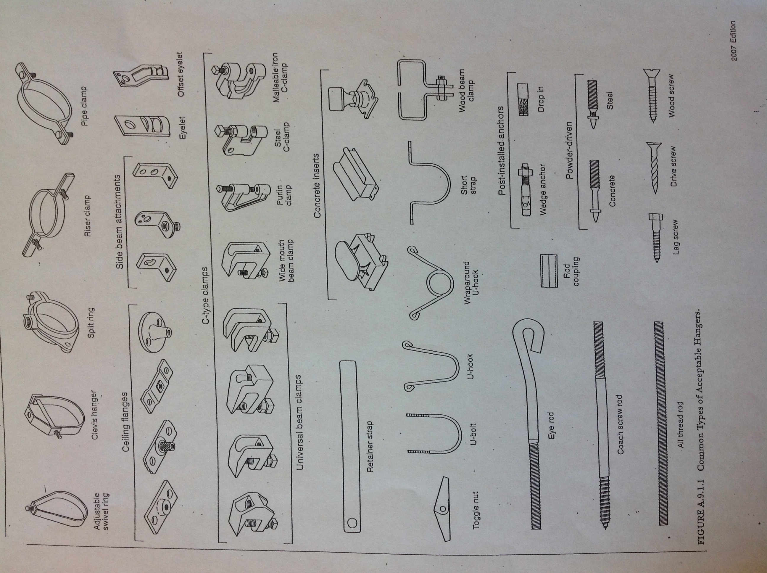
- Hanger types
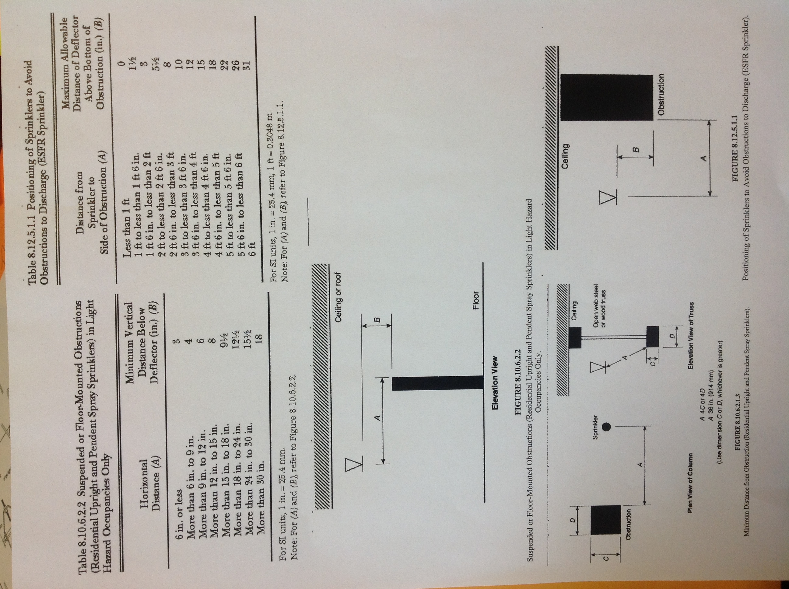
- head positioning
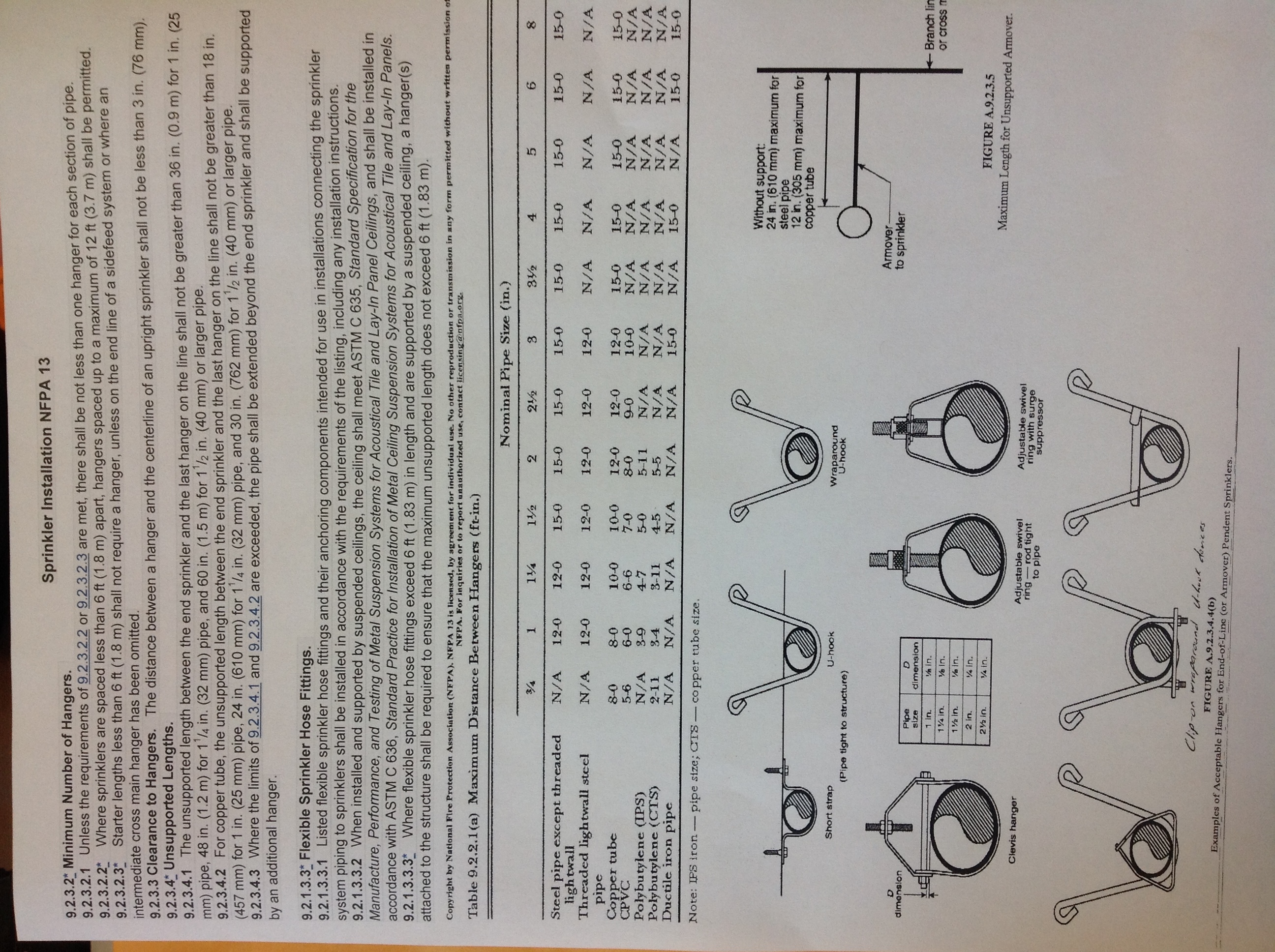
- general info
-
Hanger types
-
Head positioning
-
General Information
-
SPRINKLER PIPING - POSITION - SPACING - OBSTRUCTIONS?
-
What is wrong?
-
Date of reinspection?
-
SPRINKLER PIPING - POSITION - SPACING - OBSTRUCTIONS?
-
RISER VALVES OR FDC FREE OF OBSTRUCTIONS?
-
Date removed?
GENERAL DATA:
-
NUMBER OF SYSTEM RISERS?
-
Which riser is it?
-
Which riser is it?
-
Which riser is it?
-
Which riser is it?
-
AREA OF PROTECTION?
HYDRAULIC NAMEPLATE DATA:
-
Is hydraulic design information posted?
-
Entered date posted
-
Door to sprinkler room properly labeled?
-
FDC service areas properly labeled?
FIRE SPRINKLER TESTING:
-
FIRE SPRINKLER TESTING: Check if yes.
Hydrostatic Pressure Testing
-
Hydrostatic Pressure Testing - Type of system?
- Wet
- Dry
Wet system
-
Time and date hydro test started
-
Time and date test ended
-
Hydrostatic Pressure Testing Status WET?
-
Time and date hydro re-test started
-
Time and date test ended
-
Hydrostatic Pressure Testing Status WET?
-
Time and date re-test started
-
Time and date test ended
-
Hydrostatic Pressure Testing Status WET?
Alarm trip status wet
-
Date of alarm trip test
-
ALARM TRIP STATUS?
-
Date of alarm trip status re-test?
-
ALARM TRIP STATUS?
-
Date of alarm trip status re-test?
-
ALARM TRIP STATUS?
Dry system
-
Date and time DRY hydro test started?
-
Time and date test ended
-
Hydrostatic Pressure Testing Status DRY?
-
Is this an NFPA 13 exemption (less than 500 gal system)?
-
Time and date of DRY hydro re-test?
-
Time and date test ended
-
Hydrostatic Pressure Testing Status DRY?
-
Time and date of Dry hydro re-test?
-
Time and date test ended
-
Hydrostatic Pressure Testing Status DRY?
Flow test dry
-
Date of flow test?
-
FLOW TEST STATUS?
-
Date of flow re-test?
-
FLOW TEST STATUS?
Main drain test
-
Date of test
-
Is it piped to exterior?
-
MAIN DRAIN TESTING STATUS?
-
Date of Main Drain re-test?
-
Is it piped to exterior?
-
MAIN DRAIN TESTING STATUS?
Fire Alarm test
-
Alarm panel monitored by central monitoring agency?
-
Name of monitoring agency?
-
Water flow/tamper activated alarm panel?
-
Horn/strobe above FDC?
-
UListed Alarm Panel?
-
Control valves properly labeled?
-
Control valves properly secured with tamper switches?
-
Fire Hydrant within 100' of FDC?
-
ALL SYSTEMS RETURNED TO SERVICE?
CLOSING INFORMATION
-
ANNUAL MAINTENANCE PROGRAM IN PLACE?
-
FINAL SYSTEM TESTING STATUS
DEFICIENCY ISSUES & REINSPECTION ITEMS:
REINSPECTION INFORMATION:
-
REINSPECTION NEEDED?
-
REINSPECTION DATE & TIME
-
INSPECTOR:
-
INSTALLER:
SERVICE PROVIDER DETAILS
CONTRACTING FIRM / SERVICE PROVIDER:
-
Contracting firm / Service provider:
COMPANY CONTACT - PHONE - EMAIL ADDRESS:
-
Contact information, including address, phone and e-mail:
OCCUPANCY TYPE:
-
OCCUPANCY USE?
- ASSEMBLY
- BUSINESS
- EDUCATIONAL
- FACTORY
- HIGH HAZARD
- INSTITUTIONAL
- MERCANTILE
- RESIDENTIAL
- STORAGE
- UNCLASSIFIED


