Title Page
-
Conducted on
-
Prepared by
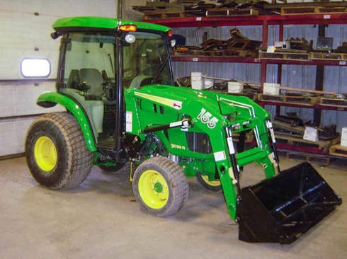
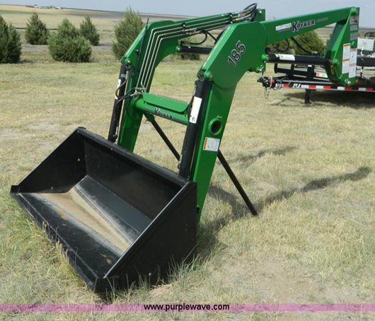
Removal of Loader Frame Attachment
-
Park the tractor on a reasonable level, flat surface the will serve as storage for the Loader Frame
-
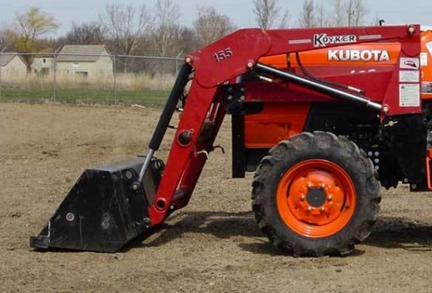
Leave Bucket attached to the Loader Frame.
-
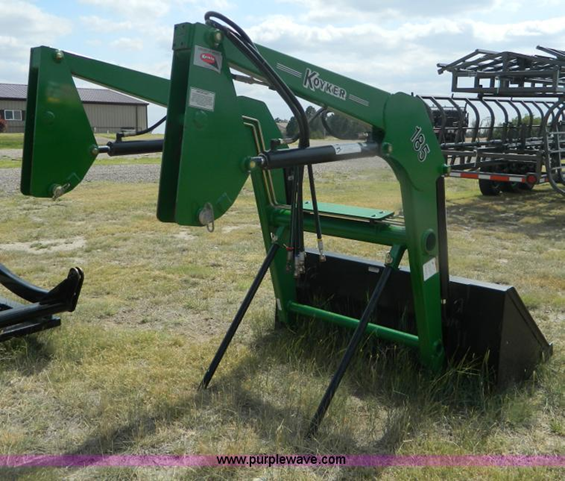
Raise Loader slightly to allow loader stands to be placed onto frame stand tubes. Install pins
-
Rotate bucket so the cutting edge is firm into the ground
-
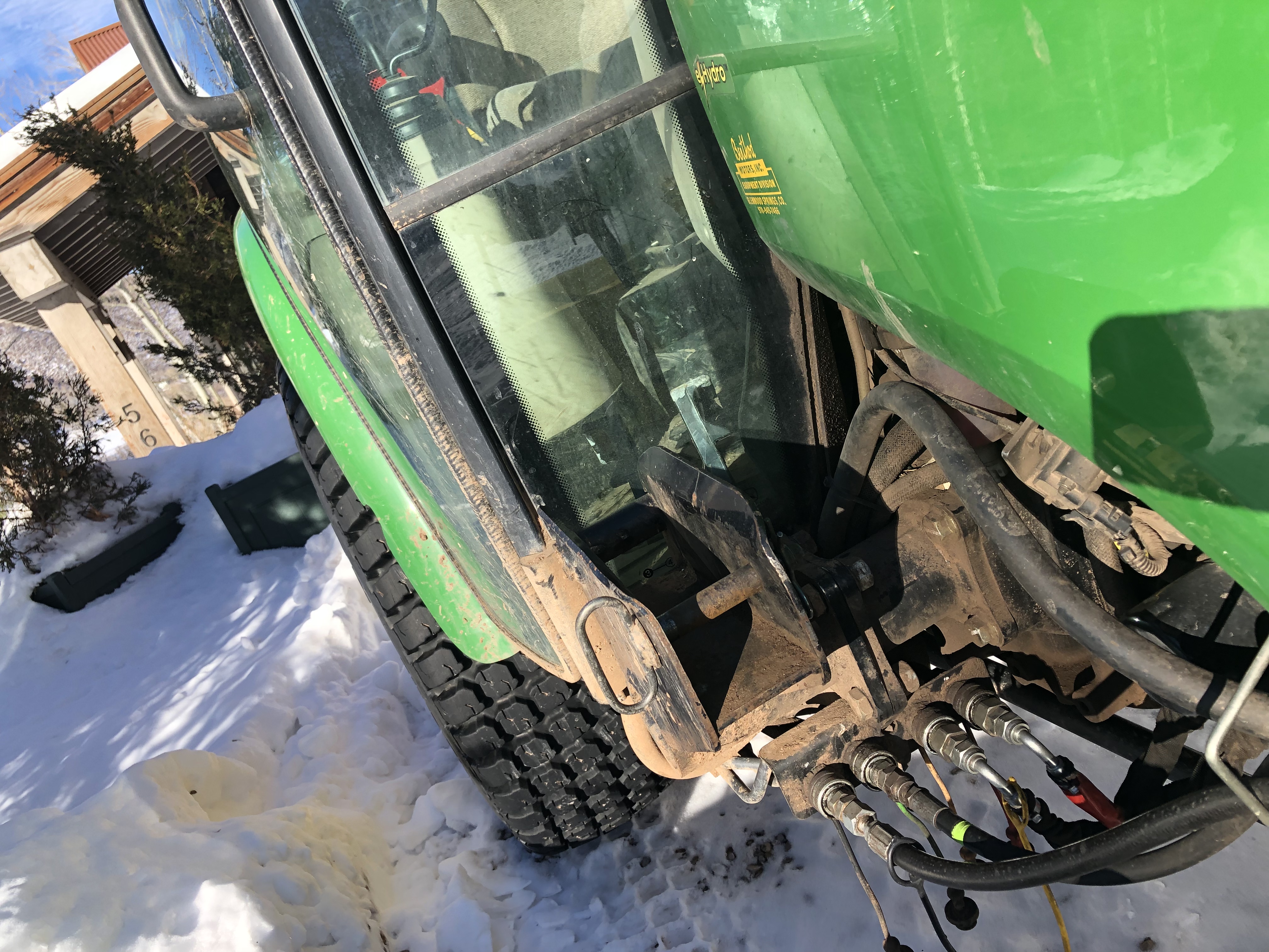
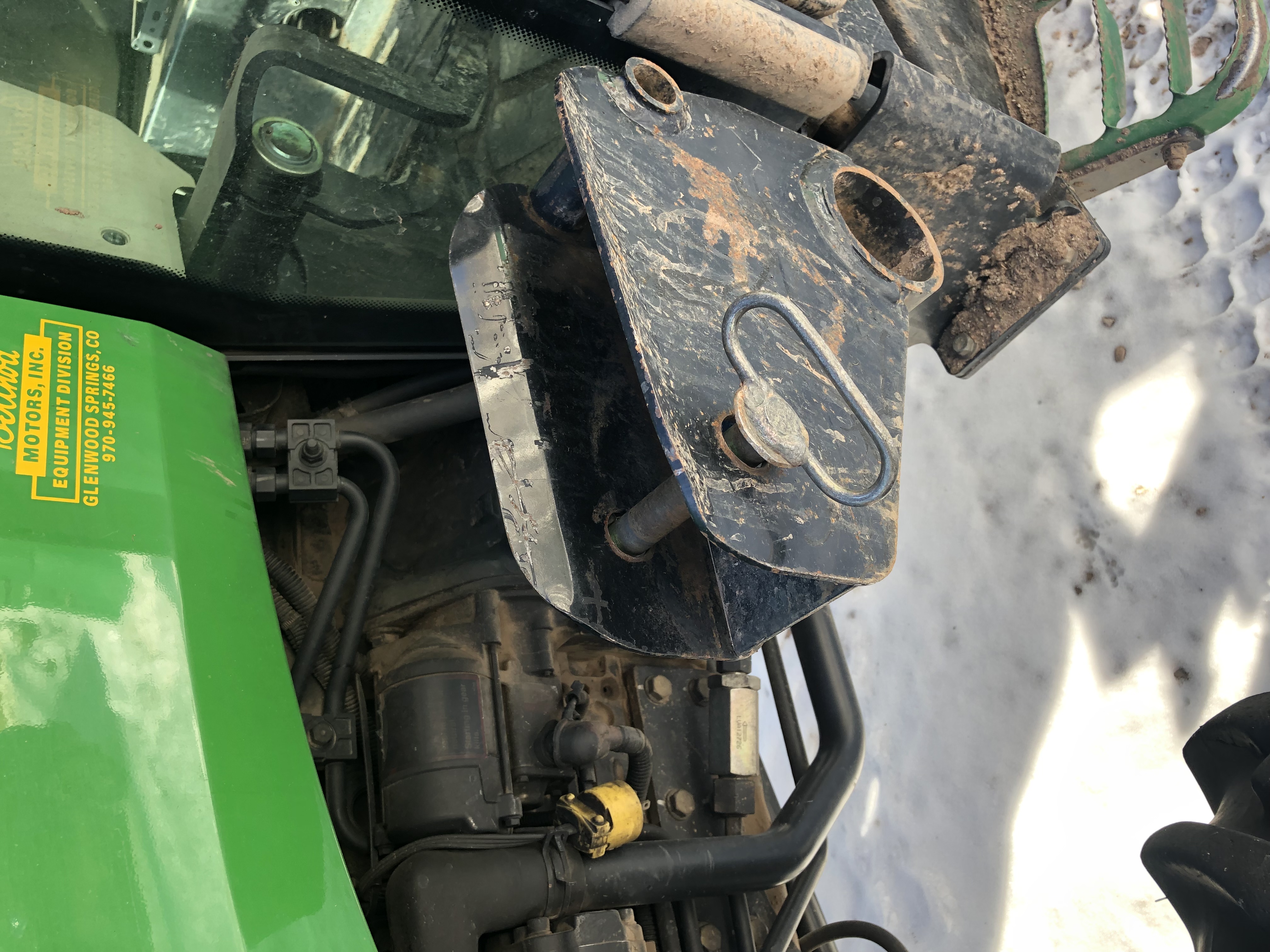
Loosen 3/4" bolt on the front of the Frame uprights
-
Remove the 3/4" locking pin
-
Carefully and very slowly back out far enough to permit separation of the upright anchor
-
Slowly rotate bucket to a flat position. this will lift frame upwards and off rear mounts
-
Turn off Engine
-
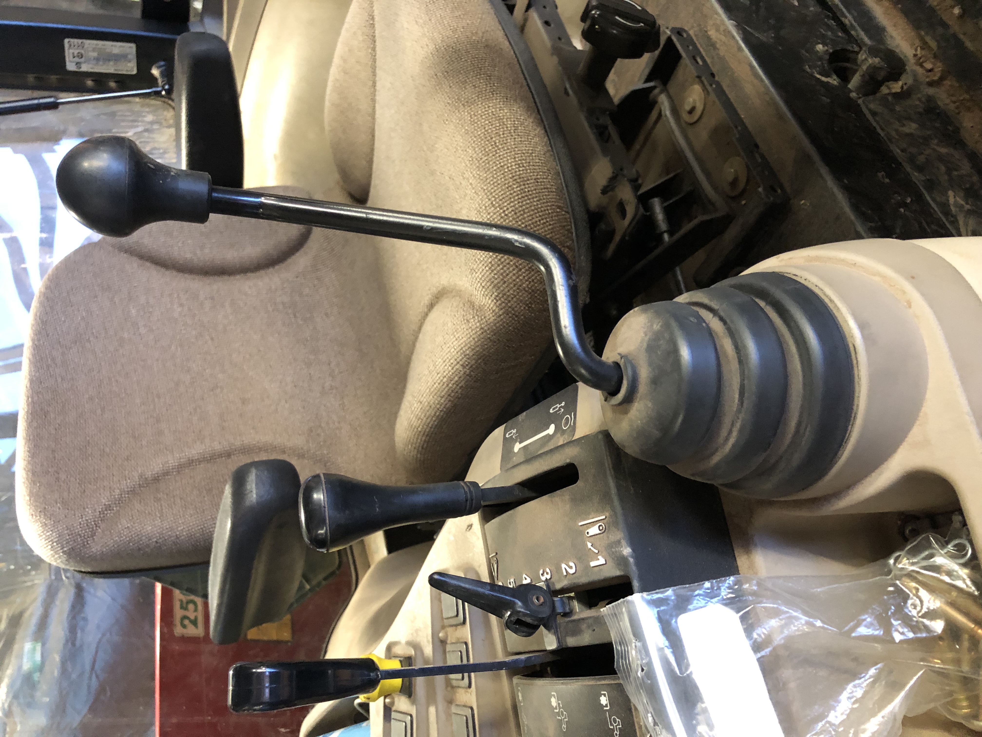
Release hydraulic oil pressure on hand levers
-
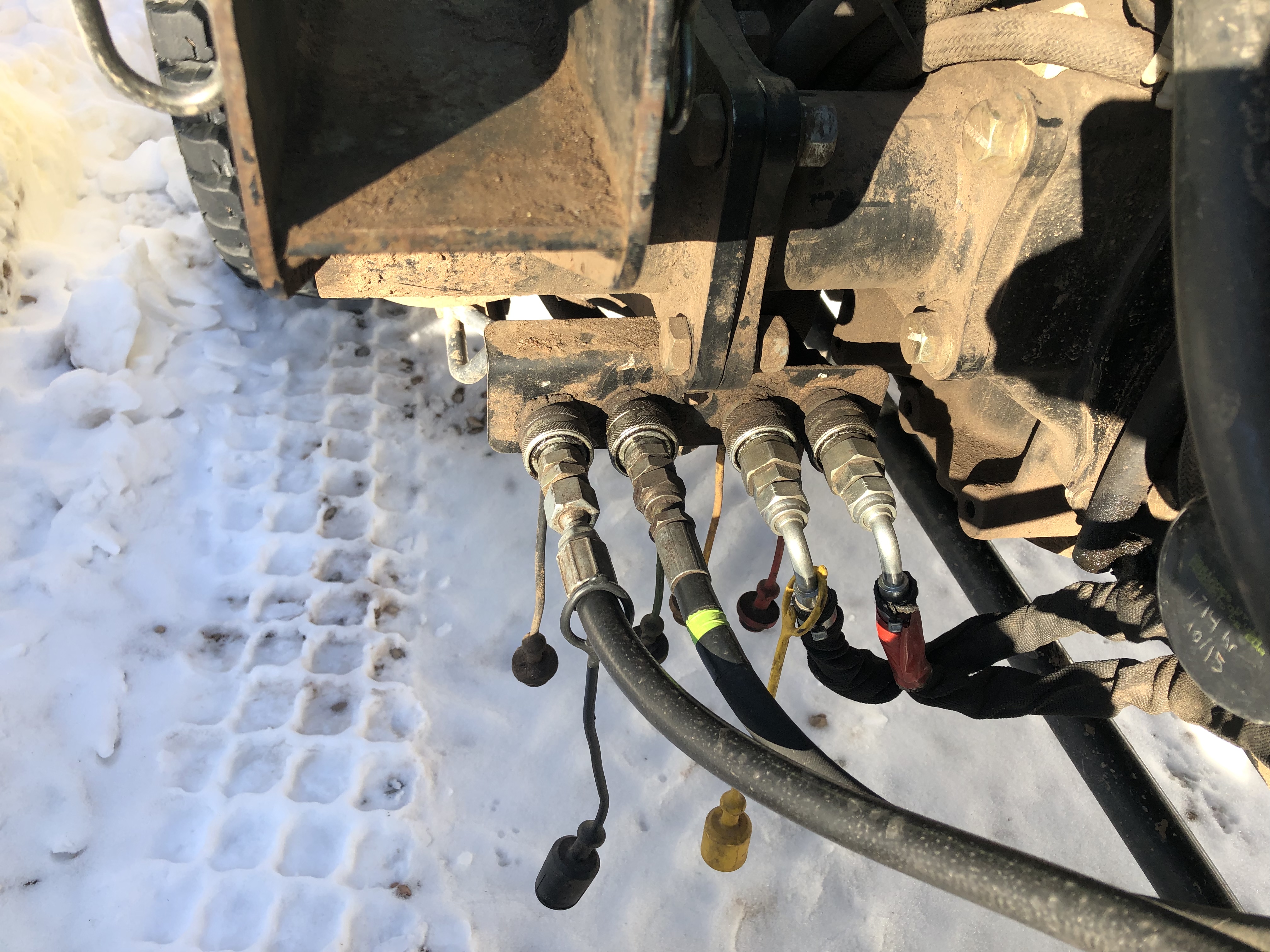
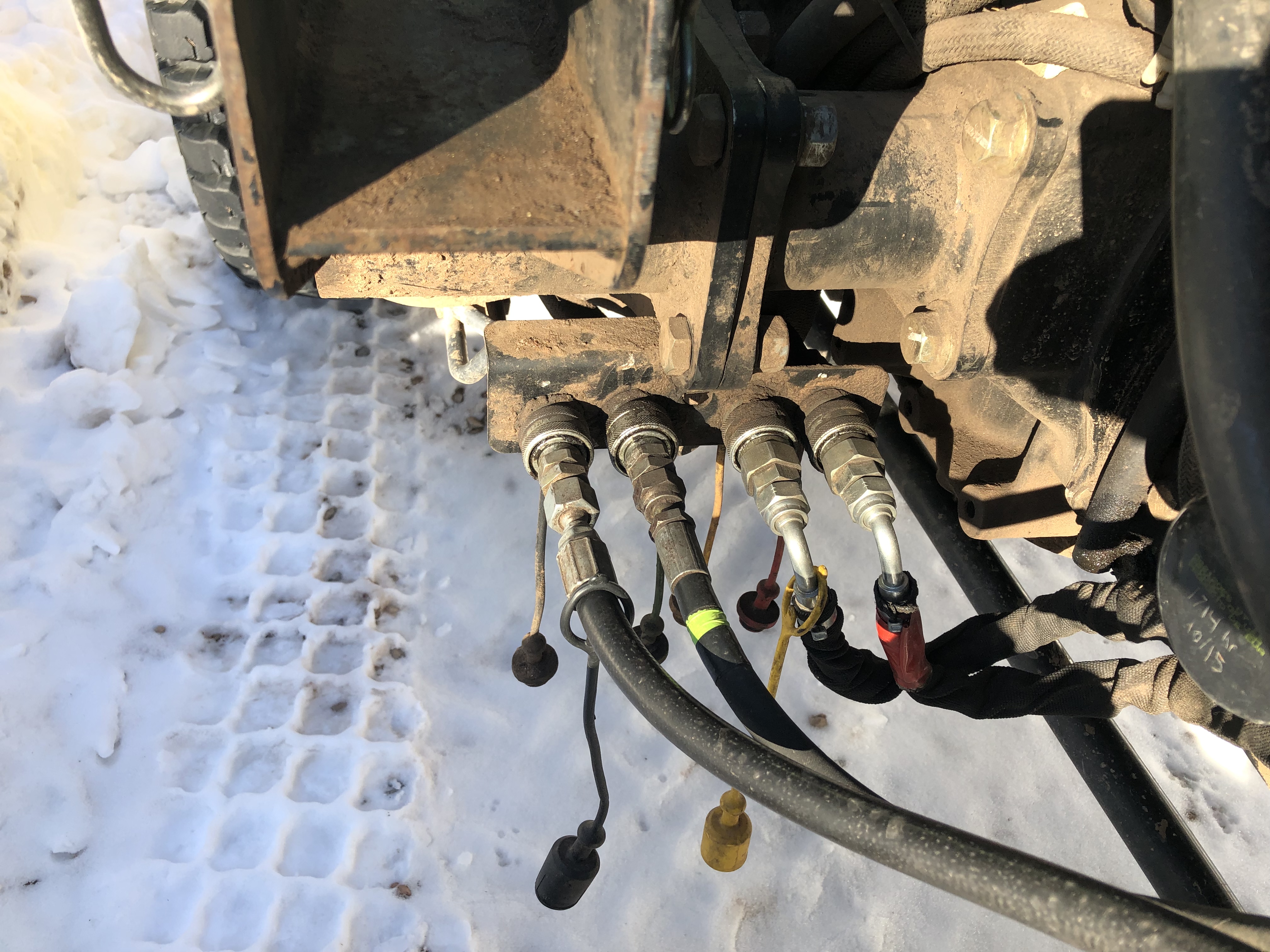
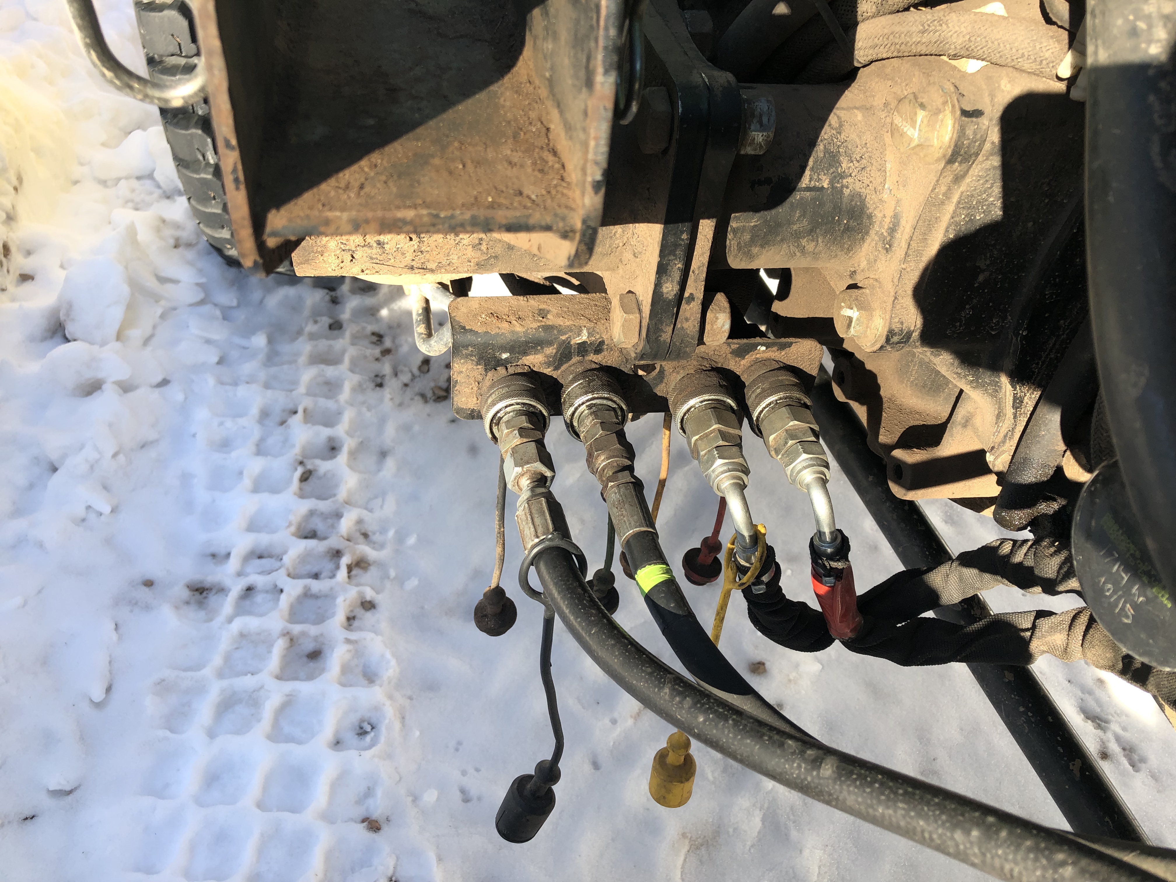
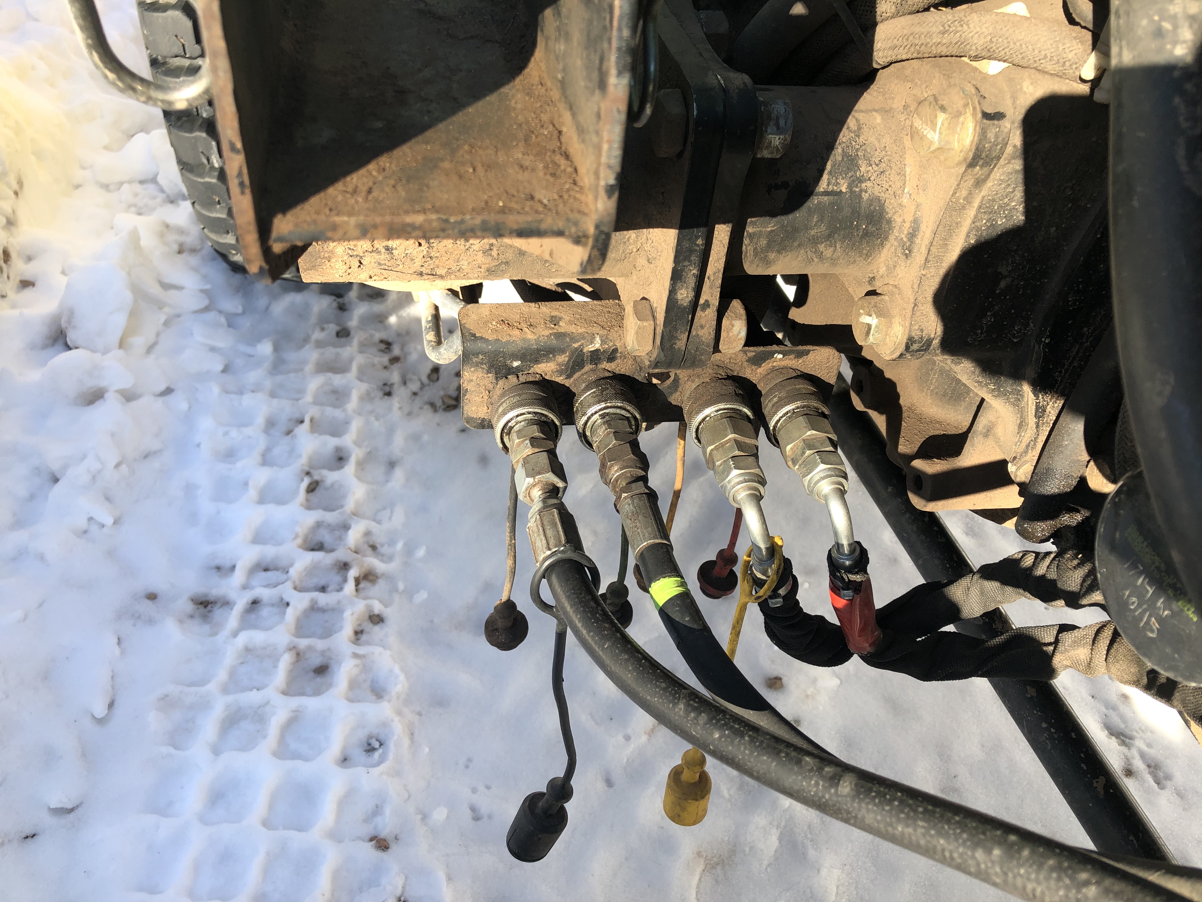
Separate quick connect for all 4 color coded hydraulic hoses.
-
Install color coded caps on hydraulic hoses and wrap in plastic to keep dry and clean.
-
Make sure the stands or blocks are safe and will support the arms while stored through the winter
-
Install color coded caps on any unused hydraulic hoses and connectors
Reverse process for installation of Arm assembly for loader and/or fork
Snow Blower Installation and removal
-
Park tractor lined up with snow blower
-
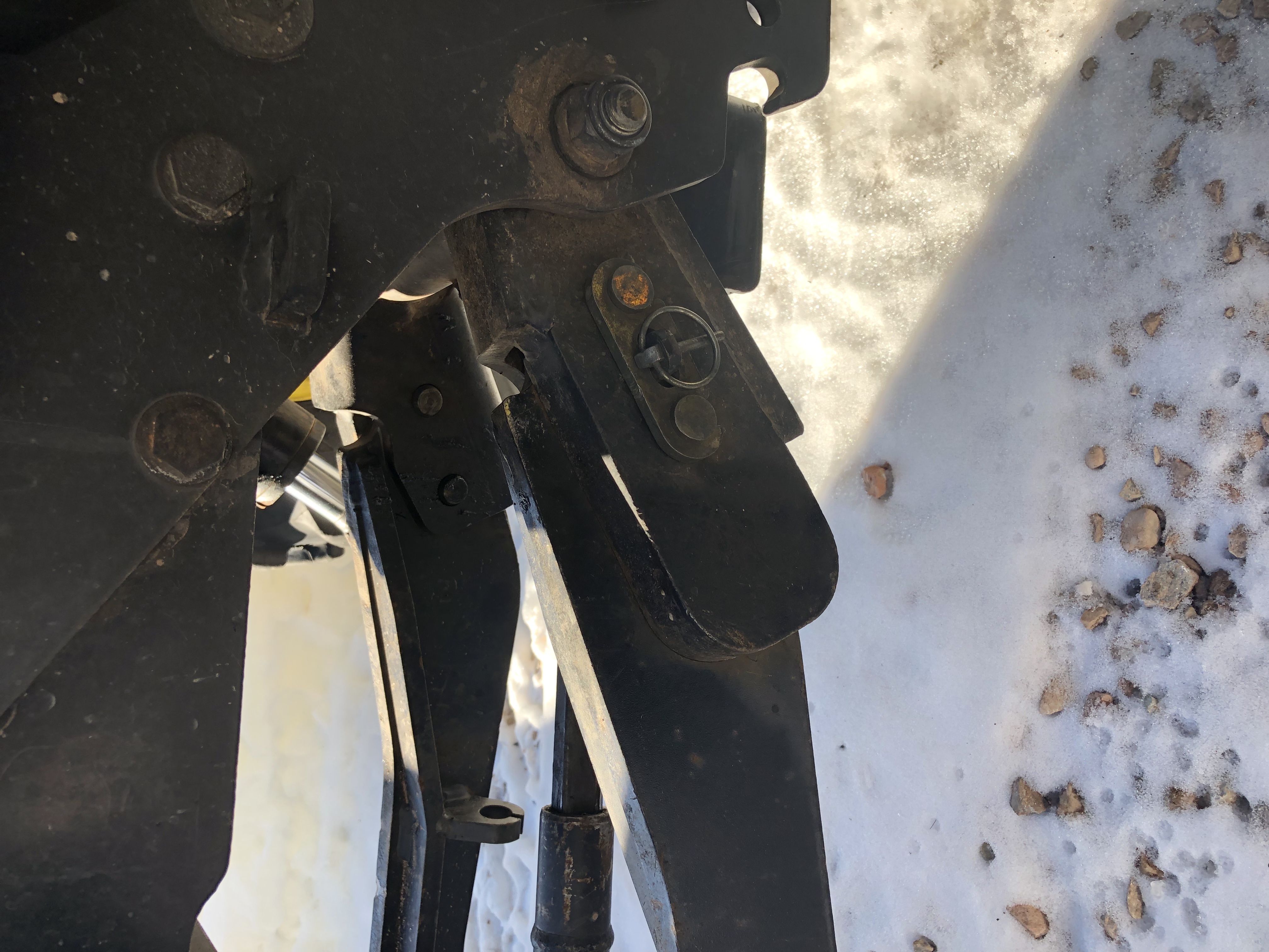
Install push arms on Deere. they will slide in the double peg system with a center cotter pin
-
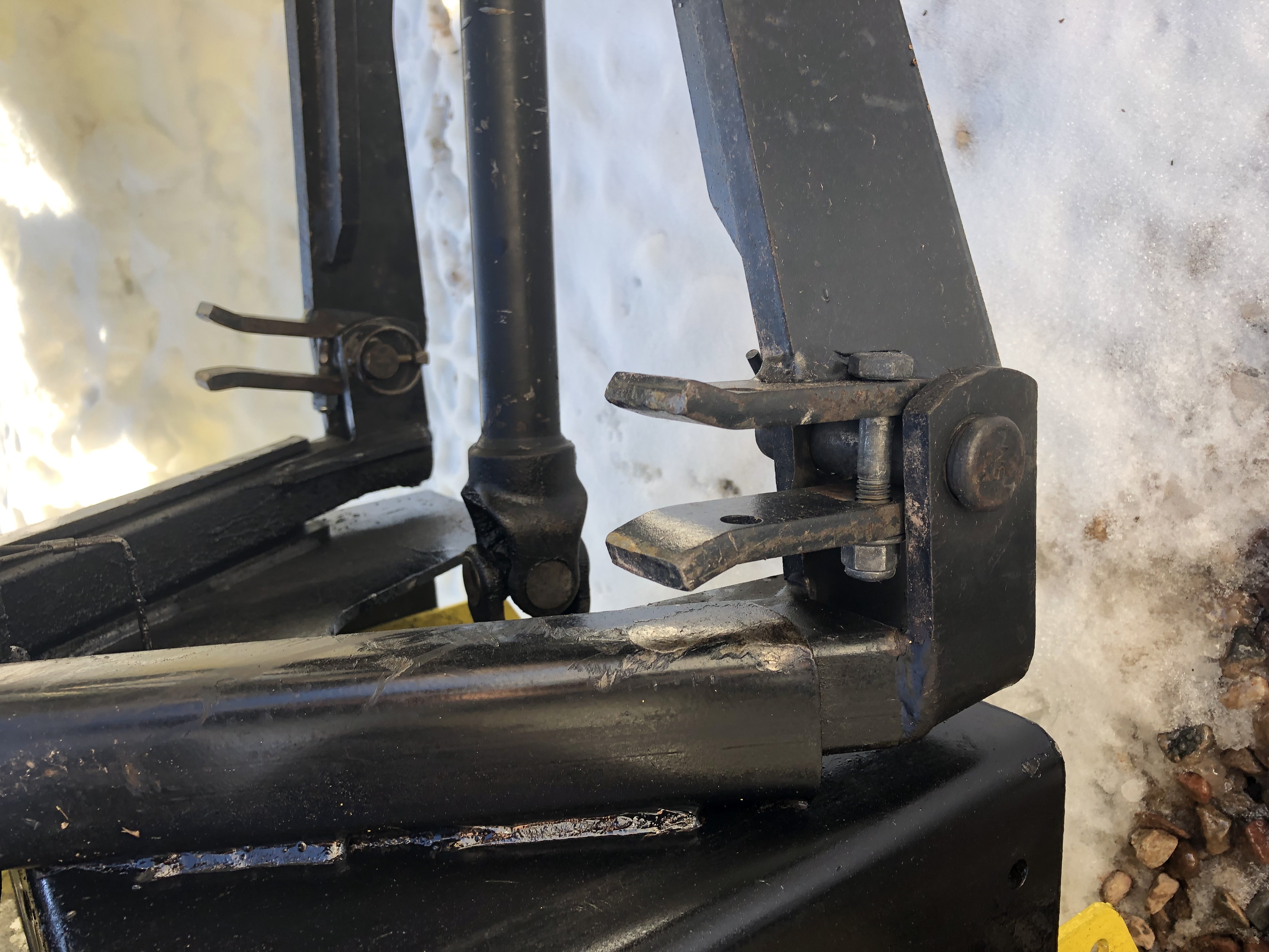
Park tractor so the push arms line up with snow blower side bottom pins, install pins
-
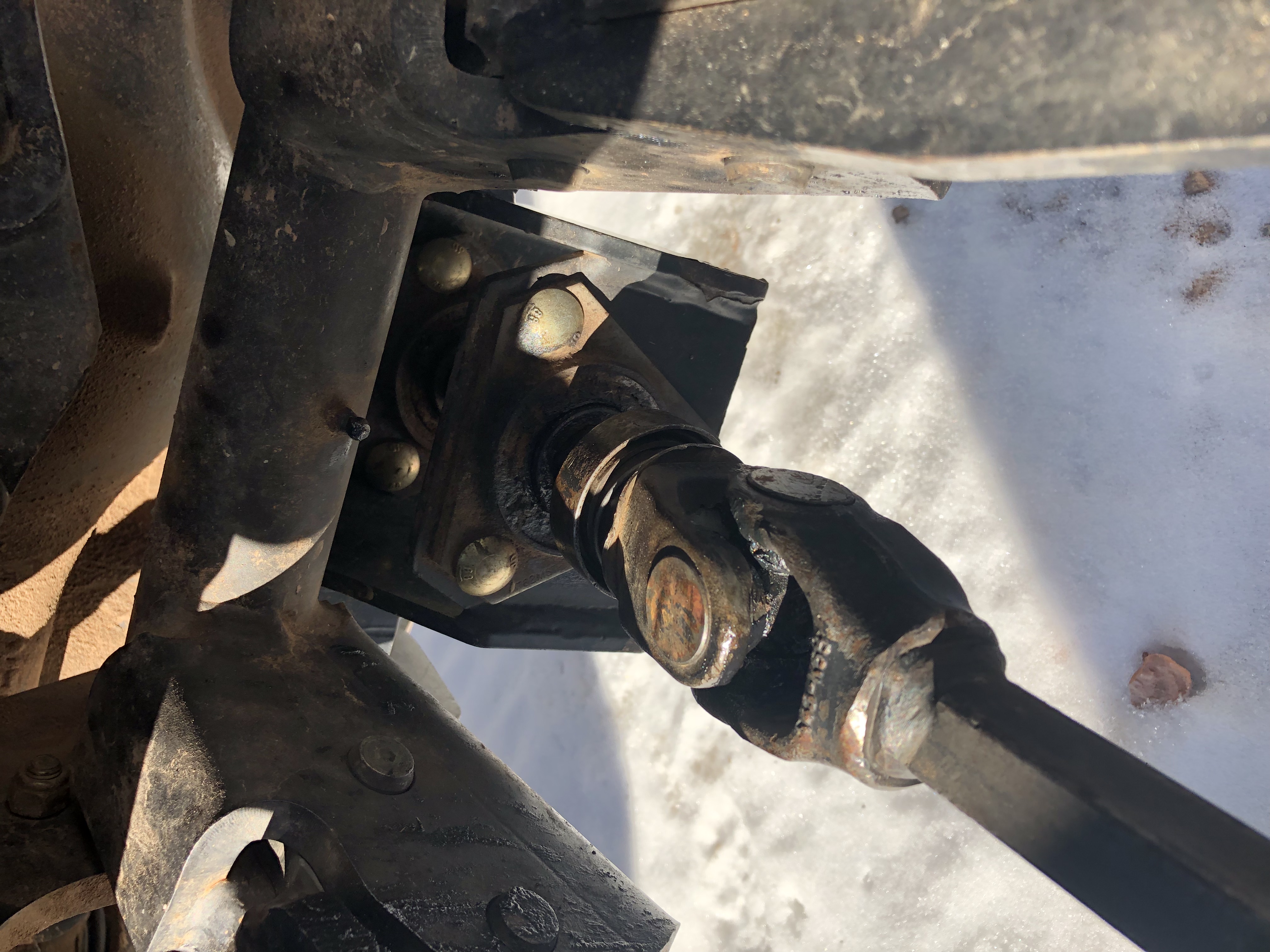
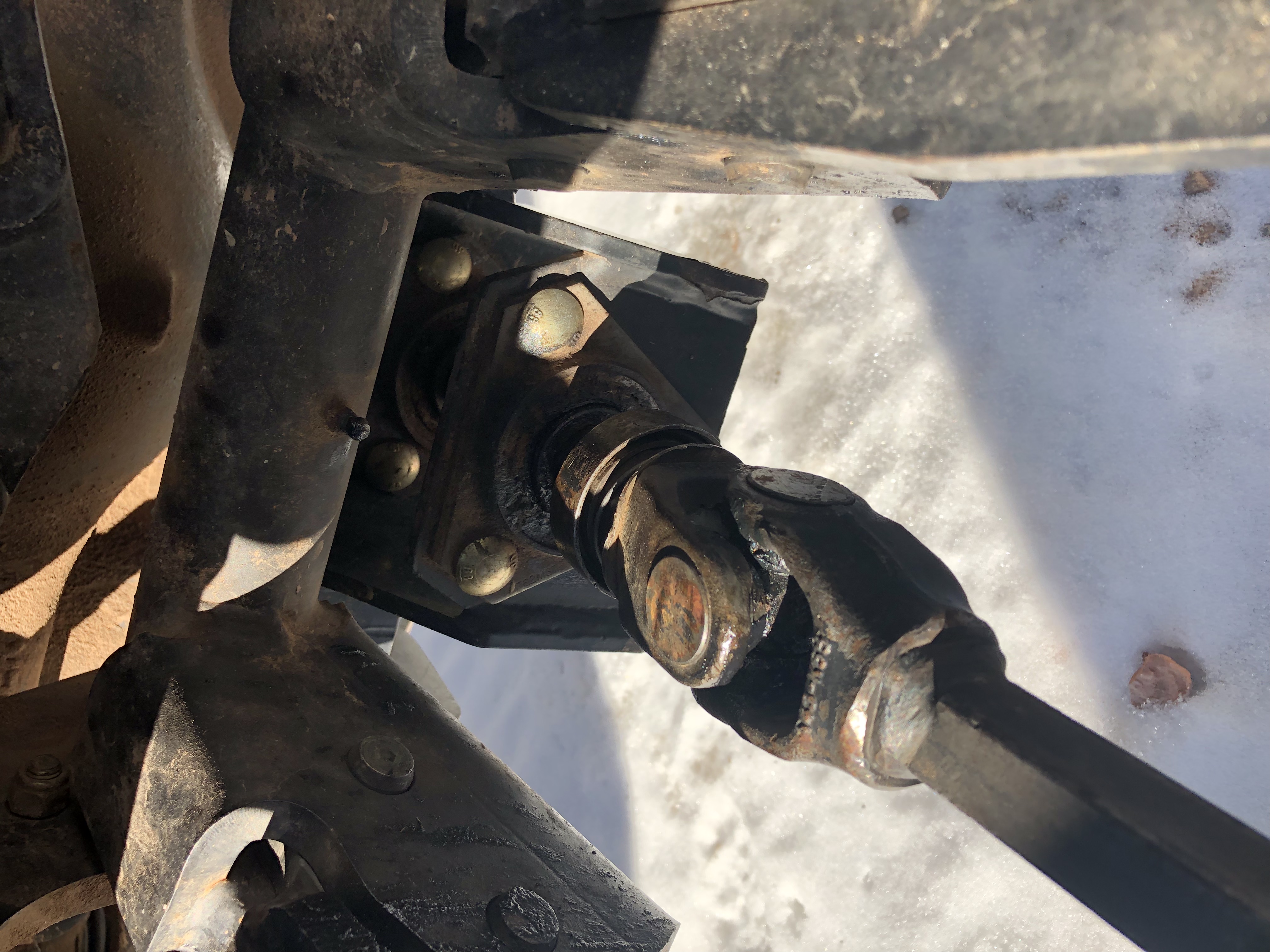
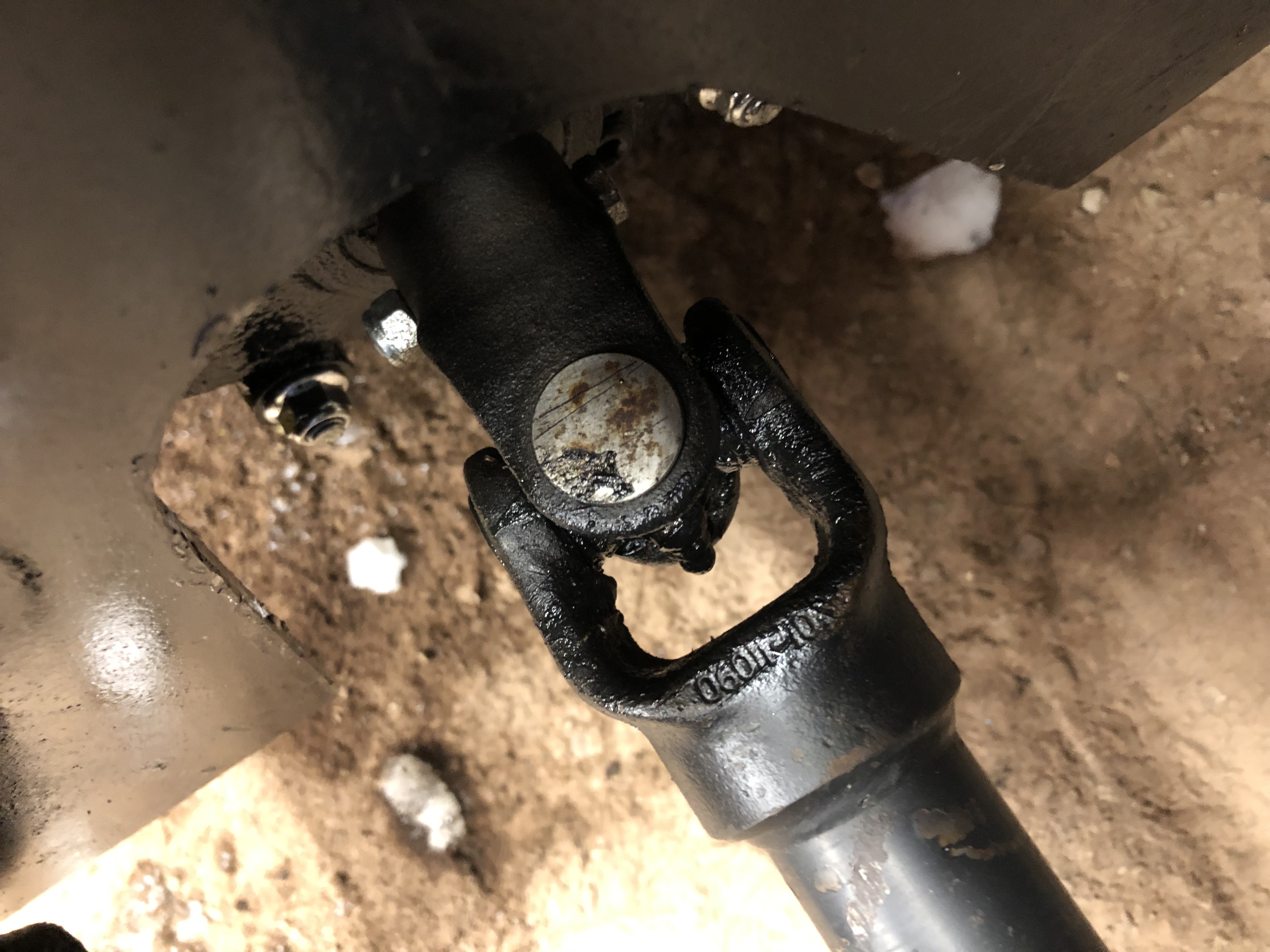
Clean drive shaft and PTO shaft receiver.
-
Align shaft splines, retract quick connect cup, extend shaft into position and ensure the quick connector locks in properly
-
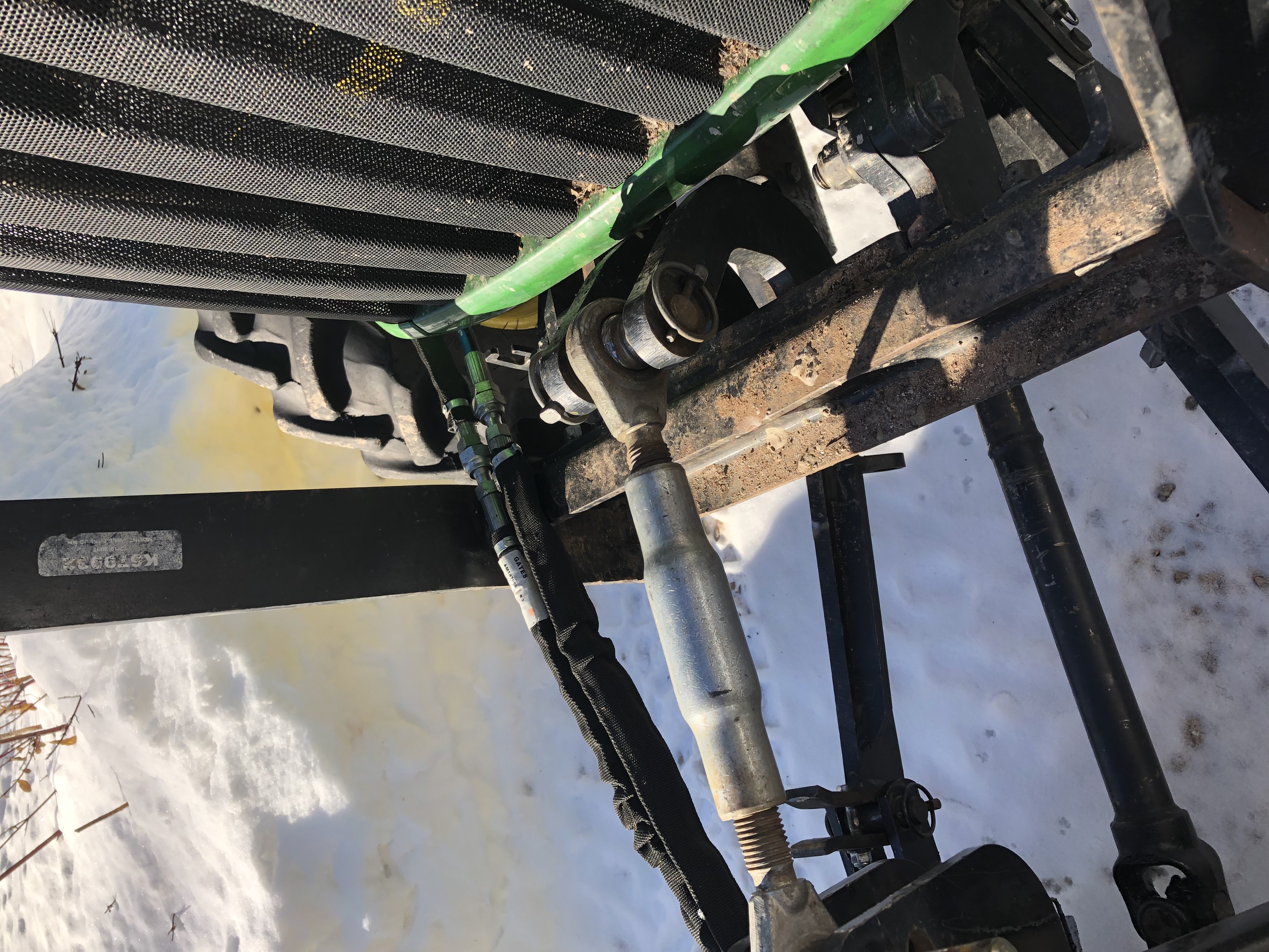
Install pin on the Top Variable Adjuster Arm
-
Connect color coded hydraulic hoses
-
Lubricate and grease snow blower fittings
-
Install color coded caps on all unused hoses and hydraulic connectors


