


Title Page
-
Instructions
• Populate all fields and return to nbn for Location ID verification.
• Photos to support the address verification must accompany this document, refer to Appendix A.
• Photos to support the scope of new build are to be included in the NBN-DES-TPL-3675 Design Pack.
• Where ‘N/A’ is selected, please provide a comment. -
Site Address
-
Site Contact Name
-
Site Contact Phone & Email
-
Survey Date
-
Site Access Arrangements
-
Body Corp / Building Management
-
Name:
-
Phone & Email:
Site Determination
General
-
Building Type
-
Heritage Site
-
Number of buildings and floors in the building
-
Please capture Details of Units against their Desired Service Class Requirement? PowerPoint for NTD Connections?
Note: SC2 Scenarios where no access is available, provide an approximate cable length from ICD to NTD (Includes 1F PIC and Clear Track Fibre)
Unit
-
Unit #
-
Required SC
-
Surveyed to NTD
-
Approximate 1F PIC cable length (Inc. Clear Track)
-
Power outlet at NTD (<1.5m)
Access and Site-Specific Requirements
-
Is there a clear lead-in to the building? <br>Identify existing duct size and capacity.<br>(Mandrel size 7mm-11mm, plus 2mm for hauling sock)
-
Duct size:
-
Existing Capacity:
-
Is there a clear pathway from the Building Entry Point (BEP) to a communications/MDF room, riser cupboard or wall cavity? <br>(Identify if external conduit and penetration is required for the proposed cable route)
-
MDU’s only – In the communications/MDF room, riser cupboard, is there clear wall or rack space available as per engineering guidelines for the proposed equipment?
-
Is there a clear pathway from the communications/MDF room, riser cupboard to the customer service location for NTD?<br>(Ensure a GPO is within 3m of proposed location and the power cord will not cause a trip hazard)
-
Does the cable pathway require a penetration into a wall, floor or ceiling?
-
Please note Building Manager approval contact details and date
-
Is access required to risers and/or access panels?
-
Is working at height required?
-
Does the Body Corporate or Owners Corporation have an Asbestos Register?
-
Has asbestos been identified?
-
Provide a copy of the register with photos identifying the locations of ACM.
-
Will there be asbestos disturbance or exposure?<br>(Entering roof space, underfloor, drilling or penetration)
-
Is there a requirement for drilling of firewalls/floors/ceilings/timber frame?<br>(Verify if fire alarm isolation is required prior to drilling, fire seal penetrations and certify where needed)
-
Number of penetrations:
-
How many penetrations require fire seal certifications.
(Note: All path of egress requires fire seal and cert – e.g A shared wall between CP and tenancy) -
Seal Only:
-
Seal & Cert:
-
Is there a requirement for trenching?
-
Are there any site-specific considerations and Hazards?<br>E.g. Pests (snakes, possums & rodents) within roof space. Pedestrian management, traffic management, confined spaces, electrical, gas leak, out of hours restrictions, etc.
-
Has detailed hazard information been completed?
-
Are any inductions required? <br>Access inductions to be detailed here for the build and future maintenance then stored in a site access database.<br>This should cover when inductions are scheduled; cost and duration; who to contact to book inductions; renewal and pre-requisites for site access to both building and customer.
-
Does the site have 24hrs/7days access for Network Operations Maintenance?
-
State what these are:
-
Does the cable pathway require any form of conduit, Internal and external, specify the required type and length.<br>E.g. square ducting, conduit, flex conduit, clear track)
-
Type
- Square Ducting
- Conduit (20mm, 35mm, 50mm)
- Flex Conduit
-
Square Ducting Length (Mtr):
-
Conduit Length (Mtr):
-
Flex Conduit Length (Mtr):
-
Provide a detailed mud map of proposed cable pathway, including cable lengths and equipment for each unit as per floor plan
-
Identify how many essential services are within the building and a suitable secure location for NTD’s with an existing GPO within 1.5mtr. <br>(Lifts, fire panels, ATMs, Medi alert)
-
Does the proposed cable pathway in a roof space consist of property crossing through a fire wall? <br>Note: Property owners will need grant and provide written consent to haul cables through a roof space for all property crossing where no common property to haul cables is available.
-
Have we received consent from all property owners to utilise part of their roof space to haul cables as per the proposed cable pathway and property crossing. <br>Note: All EU’s/owners need to be in agreeance and provide written consent where property crossing is evident. Consent is not required for CP roof cavity)
-
Has the preliminary (CWP) desktop design provided by design team been reviewed? Are the devices placed in logical locations to minimise parallel (PIC) premises cable lengths (such as placing SDTs central to tenants in riser cupboards or hallways rather than clustered at MDF room)
-
Any other relevant information?
-
Other:
-
Comments:
Appendix A
-
AVR & Supporting Artefacts - Collection Guide
Correct address and sub-address of the end user are imperative for a service to be provided and activated.
Sub-addresses are required for individual end users contained within a large and complex MDU /MPS such as Commercial Buildings and Shopping Centres.
Address and sub-address validation artefacts can be supplied in the form of a photo or document with examples shown and not limited to the items in Table 1.
An Artefact shall contain the following:
Address Validation (AVR) minimum requirements
• Name of tenancy/Shop name, (If Commercial Premises)
• Unit number,
• Floor level, I.E. Ground or Level 1, 2
• Street Address
• Supporting photos of mailbox, address plaque on doors, meters & any floor plans available on-site (such as fire exit/escape floor plans) – Ensure all photos are clear & not taken from near and far so details are legible.
Note: Corner references do not constitute an address, e.g. “corner of Smith St and Jones St”.
Table 1. Examples of Address Supporting confirmation items -
If address supporting artefacts are not available, please provide evidence by completing a Record of Conversation below.
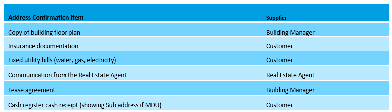
Table 2. Record of Conversation (ROC) – EU and Address Validation
-
Note: Ensure to discuss & capture details in below ROC regarding any non-standard NTD locations requested by EU/owner. Discuss and raise the possible concerns regarding hazards to their proposed NTD location that may go against NTD placement guidelines.
***Note: Internal Decon staff to use SharePoint (NBN ROC)*** -
Site Contact for address Validation:
-
Name:
-
Title:
-
Phone:
-
Email:
Item
-
UNIT #
-
Date:
-
Owner or Tenant Name and Contact Number:
-
Name of EU/owner or person tied to unit, Summary of Conversation, Issues and Comments:
Outside Network - Photos
-
Identify external Pit and asset location: FJL/BJL as per the CWP Design, ensure to add a sketch/text remark on photos advising if its P1, D1, P2, D2 as per labelled locations on CWP draft Plan so design team know what photos belong to which asset
-
Clear photo showing port entries of applicable joint (FJL, BJL, DJL) Note: Include all cable labels and Tag ID’s
-
Identify and prove (R&R) duct from FJL/BJL to LIP (Use mandrel 7mm-11mm) plus 2mm for hauling sock. Rod and rope, Identify any blockages with measurements and location photo
-
Does the duct have capacity and is fit for purpose?
-
Provide details & sketches on proposed civil route as well as required civils such as reinstatement etc… If there are alternate routes, ensure to mark up on the draft CWP pit/duct plan & advise if rod & roped
-
Is new duct required and does the pit have capacity for a new breakout
-
Clear photos of Lead-In pit and roped LIC
-
Do any pits on the proposed network require a clean out. flush or remediation?
-
Note: Has EPR Zone been considered for any installation of new NBN/Telstra elements/assets. NBN has determined that an EPR zone of 200 metres can be used for major substations, specifically when working on fibre infrastructure
MDU Site Photos
-
(Supplied photos must be clear, include close-up and wide angle)
All questions below require estimated distances and describe route with the use of specific cable. (e.g Install 1F PIC Cable apx.25m)
Device counts/quantities may change from design to design (amend Description as required)
In the event not all units can be accessed for SC3 survey, ensure to survey for SC2 (ICD location in logical location nearby & provide approximate PIC cable length, photos/details where possible)
An ICD shall act as an SC2 location when there is greater than 20m (cable route) distance from the SDT to the NTD location, or there is no dedicated pathway or pathways include internal wall cavities, or multi fibre Clear Track solution is being deployed. -
Material Type
-
PMC:
-
PIC (Ruggedized):
-
1F PIC (Non-Ruggedized):
-
1F Clear Track:
-
12F Clear Track:
-
External Pit (LIP) location to BEP
-
BEP to first fibre device
-
First Fibre Device, describe location
-
PCD to Fibre device
-
PCD to Fibre device
-
SDT 1 to Unit X NTD
-
SDT 1 to Unit X NTD
-
SDT 1 to Unit X NTD
-
SDT 1 to Unit X NTD
-
SDT 2 to Unit X NTD
-
SDT 2 to Unit X NTD
-
SDT 2 to Unit X NTD
-
SDT 2 to Unit X NTD
-
SDT 3 to Unit X NTD
-
SDT 3 to Unit X NTD
-
SDT 3 to Unit X NTD
-
SDT 3 to Unit X NTD
-
SDT 4 to Unit X NTD
-
SDT 4 to Unit X NTD
-
SDT 4 to Unit X NTD
-
SDT 4 to Unit X NTD
Required Photo Checklist
-
Photos of all external walls – (Any external conduit work/ducting required? sketch & supply photos/lengths)
-
Photos of electricity meter board, water & gas meters
-
Clear photos of entry door to each unit/apartment (Possible SC2 ICD placement for future service)
-
Photos of hallway, corridor and common areas where equipment can be placed/installed
-
Photos of existing riser cupboards, MDF, IDF locations (suitable location for new equipment)
-
Photos of proposed PCD/BFD/BUDI location (Within NBN engineering guidelines)
-
Photos of proposed secondary (SDT) equipment locations (Within NBN engineering guidelines)
-
Photos of proposed NTD locations for all units in the building (Where access is possible)
-
Photos of elevator buttons (If applicable to show floor numbers)
-
Photo of evacuation floor plan for each floor level
-
Sketch the PIC/Premise cable routes from SDTs to NTDs & provide lengths on the floor plans supplied in the draft CWP PDF file
-
Any requirement for EWP? Scissor lift or 12M EWP required? supply photos & number of days required for EWP use
Sign-off
-
Completed by
-
Date


