Title Page
-
Site conducted
-
Site Location
-
Client Description
-
Client
Location-Building-Elevation-Zone-Floor-Grid Line
-
undefined
QAC-Inspection Checklist
-
1.Subcontractor
-
2.Linked Drawings & Details Drawings used BTS_XX_DET_TBS , Data Sheet & installation guide checked
-
3.Housewrap Breather Membrane to spec seal /tape all joints with Tape
-
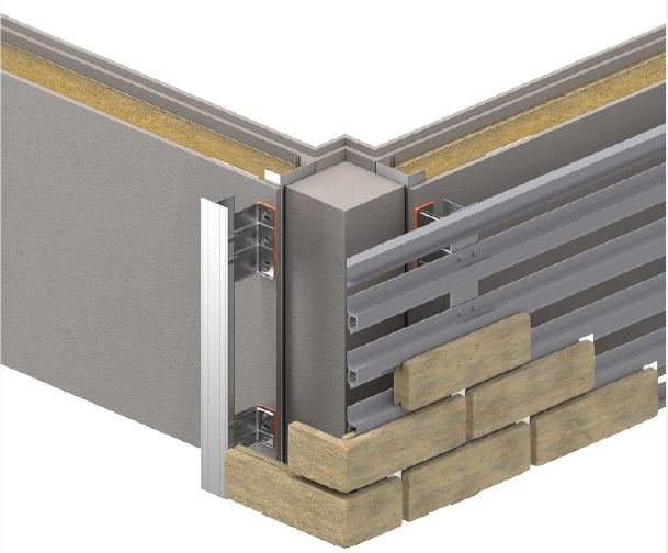
4. C`Channel & Top Hat fixed to SFS studs, GL/Datum; fixings to spec
-
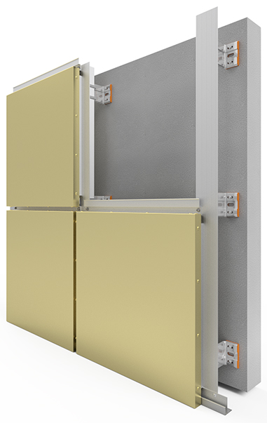
5.SINGLE BRACKETS FIXED BACK TO SFS WALL USING 2 No FX1. FIXING CENTRES ARE TYPICALLY 600mm HORIZONTAL AND VERTICAL, ALL WITH THERMAL ISOLATOR PADS. (SUBJECT TO CALCS)
-
6.DOUBLE BRACKETS FIXED BACK TO SFS WALL USING 2 No FX1. FIXING CENTRES ARE TYPICALLY 600mm HORIZONTAL AND 750mm MAX VERTICAL, ALL WITH THERMAL ISOLATOR PADS (SUBJECT TO CALCS)
-
7.VFB-Fire Barrier - Inspection of vertical cavity barriers (FB) FULL FILL CAVITY BARRIER TO SUIT CAVITY 10 mm compression check project spec, x2 Brackets required per length Siderise RV Bracket @ 600 max cc,300 from edge , x1 Brackets required if cut length is 300mm or less ,x2 Brackets required if cut length is 301-1200mm,Apply SIDERISE RFT Foil Tape to both sides of the cavity barrier joint <br>The Brackets must penetrate the firestop by 75% at mid thickness RV Cavity Barriers MUST take priority over RH <br>Intumescent Strip Installed Siderise RH25<br>
-
8.HFB-Horizontal cavity barriers - check project spec, 25mm +-3mm GAP ,x3 Brackets required per length, nominal 400mm centres,Siderise RH Bracket @400 mm cc ,x2 Brackets required per length between 100mm and 800mm,Trim split leg to 10-20mm using snips,Apply SIDERISE RFT Foil Tape the top side of the cavity barrier joint,AVOID lengths less than 100mm,Bend split leg in opposing directions using long-nose pliers making sure the bracket isholding the cavity barrier tight but not overly tight,Apply SIDERISE RFT Foil Tape to inside and outside of the RV to RH cavity barriercorner joints around openings.Make sure the cavity barrier is tight around the rail, if there are any gaps, pack with RV/RH offcuts and seal wising SIDERISE RFT Foil Tape.Corner joints should be mitred to ensure a continuous line of intumescent.<br>Additional Intumescent Strip Installed Siderise RH25 where gap is over 25mm <br>
-
Handover Joint Inspection BTS
-
Handover Joint Inspection Client
Hold Point 1: L&T Rails , Rockwool Inulation
-
-
9.VERTICAL RAILS T- RAILS 65x50x2.2mm & L Section 40x60x2.2mm @ . ALL FIXED BACK TO HELPING HAND BRACKETS AS FOLLOWS: (SUBJECT TO CALCS) SINGLE BRACKET -2 No FX2 THROUGH<br>SLOTTED HOLES (SLIDING FIX) DOUBLE BRACKET - 2 No FX2 THROUGH HOLES (DEAD FIX)<br>
-
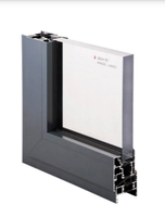
10.Windows Cills & Flashings Aluminium Cleat Support – fix to L & T rails B#Insect mesh @ Bottom & Top of the Cladding - check project spec B# Aluminium PPC: Jamb Closer,PPC Ventilation,Corner ,Drip flashing – project spec
-
11.Rockwool Rainscreen Duo Slab TBC MM THICK or check project spec,fix with Textured outer face of slab, Close butt the slabs at all vertical and horizontal joints, Stagger the horizontal joints min 100mm, Fixings min 1 no metal and 2 no polypropylene per board, @ max 500 cnts, minimum head diameter of 70mm.U Value of min 0.16W/m2K- check project spec<br>
-
Handover Joint Inspection BTS
-
Handover Joint Inspection Client
Hold Point 2 : Rails Installation of Starter & Middle & TopRails Bricks Support
-
12. A#Starter Rail Bricks Support is affixed at the base of the elevation .B#Middle Rails Bricks Support are the correct orientation, at 75mm increments, including Use the gauge tool to fix multiple rail courses simultaneously check project spec.C#Top Rail Bricks Support Complete the elevation with the top rail for a neat finish.D#Aluminium PPC: Jamb Closer,PPC Ventilation,Corner ,Drip flashing – project spec
-
Handover Joint Inspection BTS
-
Handover Joint Inspection Client
HOLD POINT 3 : Installation of Brick Slips
-
13.Bricks -Strat Setting Out from Corner & Windows Head & Jamb & Between
-
14.Slip MechSlip Brick Tiles firmly into place between rails, guided by the preformed upper and lower retainers. Repeat the process for the remaining bricks, ensuring that there is a metal brick spacer installed in the vertical joints between individual bricks.
-
15.Brick Spacer Clips to all joints,automatically create a 10mm wide vertical (perp) joint between bricks, a 10mm horizontal (bed) is created by the upstand of the rail profile.
-
16.Joints 10mm-Ensure perp joints align as traditional brickwork and are typically positioned half way between the brick immediately above and below
-
17.Movement Joint Horizontal Joint Base Every 7M as per location/datum/details
-
18.Vertical Joints Base every 15m as per location/datum/details
-
Handover Joint Inspection BTS
-
Handover Joint Inspection Client
HOLD POINT 4: Installation of Easipoint Historic Mortar or similar
-
19.Protection to Windows & Glass & Cills & Scaffolding & MEWPS & Other Contractors
-
20.Parex Easipoint Historic Mortar or similar check project spec Ral Color
-
21.Inspection of Mechslip Brick Slip
Comments
-
COMMENT Reference & Descrition
-
Comments Reference & Description date when closed (BUILD THERM)
Hand Over Joint Inspection
-
Hand Over -Cladding free from damage-Facades to be viewed as per the BBA, in daylight from a distance of not less than 10m. Some variation in colour and texture of external walls is inevitable and in certain cases is a feature
-
On behalf of Build Therm (name)
-
On behalf of Main Contractor (name)
