Title Page
-
Document nr
-
Description
-
Site conducted
-
Prepared by
-
Date
-
Site Location
-
Client Name
-
Other Comments
A. Client Handover
-
Grid Lines and Datum, Safe area of work, Skip ...
B. Drawings
-
Design, Details Drawings, Data Sheet & installation guide checked
C. Location
-
Block ,Level,Elevation,Grid LIne location on site
D. Other Comments
-
undefined
QAC-Inspection Checklist
- SURVEY OF BACKGROUND WALLS
-
Before starting work carry out a survey to confirm suitability for application of external wall insulation system. Any repairs and/or additional works necessary to render the background suitable to receive the system(s).Note: The system will follow the line of the existing wall surfaces. If wall surfaces deviate from plumb/line/level corrections to this must be made, by others, prior to installation of the system.
STRUCTURAL SUBSTRATE
-
Description: Minimum 12 mm exterior cement-bonded particle board to EN636 Part 1 or min. 12 mm RCM Y-wall (Class A1 – non-combustible) cement fibre board on vertical galvanised top hats forming a drained cavity, all designed supplied and installed by others in accordance with BS 5950 and/or the relevant Eurocodes.<br>– Preparation: Surfaces shall be clean and dry. Sheathing boards shall be flush with all joints less than 2 mm in height and with screws fully driven into board and finished flush. All fixings shall be non-corrodible and suitable for the exposure conditions.
Pictures and Other Comments
-
-
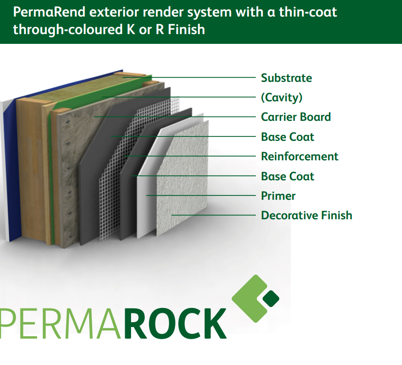
System reference: PermaRock Mineral Fibre System - Adhesive & mechanical fix.
-
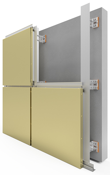
Ventilated System .25 mm CAVITY SPACER FIXED THROUGH SHEATHING BOARD INTO STEEL STUDS CREATING A CAVITY BEHIND THE INSULATION BOARDS. Vertical spacer rails are mechanically fixed at maximum 600 mm horizontal centres to the sheathing board and at a maximum of 300 mm centres either side of the rail. Rails may need packing to ensure they are true to line and level. Drainage-deflection channels are mechanically fixed over all window and door openings, and horizontal and vertical intumescent strips are installed following the designer’s instructions. Carrier Board installed to Vertical Rails , fixings at 300mm centres.
-
Breather Membrane to spec seal /tape all joints with Tape. Horizontal laps should be at least 100 mm and vertical laps 150 mm. Vertical laps should be staggered wherever possible. External corner min 300mm
-
Insulation<br>– PermaRock Mineral Fibre DD Insulation. Hydrophobic, high laminar and compressive<br>strength fire resistant, mineral (stone) wool, manufactured into rigid boards high density<br>external face and lower density core.Maximum size of mineral fibre insulation boards: 1200 x 600 mm
-
Starter Track<br>i. PermaRock Starter Track: Shall be fixed horizontally at the base of the system in the required position, true to line and level and in full lengths wherever possible. Starter tracks shall be mechanically fixed through the back plate with the appropriate type of PermaRock Profile Fixings at 300 mm centres with additional fixings 50 mm from each end, and keeping the back plate as<br>close to the wall surface as possible.<br>ii. If necessary, use PermaRock PVC packing shims to ensure that the starter track is installed straight. Adjacent lengths shall be connected using H-connector pieces (Ref: 698/01).<br>iii. Attach the clip-on drip edge nosing, ensuring that lengths of the nosing span across joints between starter tracks by min. 200 mm.<br>iv. Fill any gaps between the starter track and the wall surface with PermaRock PU-Foam.
-
PermaRock Mineral Fibre Insulation board .The first insulation slab is positioned on the starter track and secured into the cavity spacer tracks using a selfdrilling, self-tapping fastening. Subsequent slabs are positioned so that the joints are staggered and overlapped at the building corners . Care must be taken to ensure the fixings are not overdriven.
-
PermaRock Mineral Fibre Insulation board fixed with adhesive layer to rear of board. Basecoat Adhesive render to rear of boards. For the rear of the insulation boards, the adhesive basecoat should be applied using a 10mm serrated edge trowel to follow the shortest direction.<br>
-
Insulation, fix with Textured outer face of the slab, close edges of the slabs at all vertical and horizontal joints, Stagger the horizontal joints min 100mm, Fixings min 1 no metal and 2 no polypropylene per board, @ max 500 cents, minimum head diameter of 70mm. Ensure that all insulation slab edges are butted tightly together, and alignment must be checked as work proceeds. The surface of the boards should be smooth without high spots or irregularities.check project spec
-
Insulation at Windows and Doors: Cuts to openings to be formed with a L shape cut. Min cuts 200mm.
-
Boards to corners.Lapped toothed detail for all boards to corners. When installing the insulation boards to corners ensure that boards are staggered and lapping to form a toothed detail, as above. No cuts less than 200mm thick. Allow fixings to corners at 300mm centres and no less than 200mm from the edges. Ensure L shape cuts to corners of openings as detail provided
-
Deflection Channel Details .To fit around details such as doors and windows, insulation slabs may be cut with a sharp knife or a fine-tooth saw. Purpose-made window-sills, seals and deflection channels are fitted , which are designed to prevent or manage water ingress and allow water to be shed clear of items bridging the cavity. Drainage deflector bedded on silicone sealant and mechanically fixed at 300mm centres to sheathing board. Bead to be fitted above window and door openings fixed at min 10 degree slope
-
High Density moisture resistant insulation for use below ground with basecoat and bituminous paint finish
Pictures and Other Comments
-
-
Insulation Fixings: PermaRock Insulation Fixings Ref. FIS150-160RF. Polyamide tube washer with 60 mm Ø head and organic-coated, anti-corrosion coated galvanized steel screw (5.8 mm Ø) with self drilling point.<br>Note: The system installer shall ensure that fixings are of sufficient length to achieve the correct embedment depth into the load-bearing substrate, taking into account the insulation thickness, thickness of the adhesive layer, and thickness of any existing render or leveling coats. Screw fixings shall be of sufficient length to show min. 10 mm thread projection through the sheathing board. Allow a minimum of 5 no. fixings per insulation board.
-
Adhesive: PermaRock Lamella Adhesive - Polymer-modified, cement-based, hydraulic hardening mineralic adhesive. Supplied as dry powder pre-mix. 100% adhesive coverage required.Adhesive<br>v. PermaRock Lamella Adhesive shall be mixed by addition of the dry powder premix to clean water in a clean mixing vessel using a rust-free low speed electrical paddle mixer in accordance with PermaRock recommendations
-
Mineral Fibre Insulation .Where boards abut other surfaces, such as window frames, sills, soffit boards, etc., the insulation<br>boards shall be cutback from the abutting surface to enable the appropriate sealing tape or window sealing strip to be applied to the abutting surface prior to the insulation board being fixed into place.<br>ix. Using a stainless steel trowel, apply adhesive to the back face of the insulation boards using a method appropriate to the substrate type as indicated below.<br>x. Ribbon method (blockwork, brickwork and uneven concrete surfaces): Adhesive is applied as a continuous ribbon, approx. 60-70 mm wide, to the full perimeter of the back of the board. Do not apply PermaRock Adhesive to the substrate. Additional ribbons of material are applied at ca. 300 mm centres . Adjust the thickness of the applied material to the tolerances of the<br>substrate, such that > 35% of the surface area is in contact with the adhesive. <br> Notched Trowel method (flat substrates, including sheathing boards and smooth/flat concrete surfaces): Adhesive is applied as a thin scrape coat covering the full surface of the back of the board using a flat trowel to ensure that the material is worked into the fibres of the board. Additional material is then applied by 10 mm serrated or notched trowel and combed along the<br>length of the board (i.e. horizontally –. Do not apply Adhesive to the substrate.xii. Insulation boards shall be fixed horizontally, true to line and level, and commencing at the starter track at an external corner.<br>xiii. Immediately transfer the adhesive-coated board to the substrate, with the bottom edge of the board sitting in the starter track.<br>xiv. Press the board on to the wall so that the adhesive layer is spread out sufficiently to provide a good bond to the substrate, with the face of the board tight up to the front lip of the starter track
Pictures and Other Comments
-
-
PermaRock Starter Track BAS150MF/6 Aluminium starter track with clip-on uPVC drip edge bead.<br><br>
-
PermaRock Corner Profiles COR/PL/M uPVC corner angle with alkali-resistant glass fibre mesh ‘wings’
-
PermaRock Window Seal Strips: Ref. BEA/PWSS/LA26/EWI/2.6. For 3D movement-capable weather seals at heads and jambs of window/door frames
Pictures and Other Comments
-
-
Reinforcing Layer: PermaRock Bedding Mortar: High impact-resistant, water vapour permeable, polymer-modified, cement-based base-coat for reinforcement layers on PermaRock Insulation backings.
-
PermaRock Reinforcing Mesh: Alkali-resistant, multi-strand, glass fibre reinforcing mesh.
-
PermaRock Armoured Mesh: High strength/heavy duty alkali-resistant, multi-strand glass fibre reinforcing mesh for walls requiring additional /enhanced impact resistance: Locations to be marked on the project drawings.
-
Reinforcement layer (fire safety) fixings: ref - FIS/160-170SB/SS. HA36 stainless steel washer head with 200mm JT3 stainless steel screw. Application through the reinforcement layer on a max. 600 mm x 600 mm square grid pattern with additional fixings at building corners (max. 300 mm ctrs) and around structural openings (max. 300 mm ctrs). See Clause 320 – Wind Loading.
Pictures and Other Comments
-
-
PermaRock K&R Primer. Pigmented, special synthetic binder coating as basecoat under PermaRock SiliconeULTRA K-Finish. Colour as K-Finish.
-
PermaRock SiliconeULTRA K-Finish. Through-colour decorative, textured exterior render/plaster.Highly water repellent and highly water vapour permeable. High functionality against mould, algae and mildew growths. Colour from the Façade A1 colour range (to be advised). Grain: 1.5 mm.
-
PermaRock SiliconeULTRA Façade Coating.High performance exterior façade paint with organically cross-linked nano-quartz particles in a special silicone resin/binder.Application by brush, roller or airless spray.
Pictures and Other Comments
-
-
Profile Fixings: PermaRock Profile Fixing screws: PP03PT/N.
-
PermaRock Distance Spacers
-
PermaRock Sealing Tape Type 2D: SEA/054/00 (2-6 mm)
-
PermaRock Sealing Tape Type 2D: SEA/054/01 (5-12 mm)
-
PermaRock Window Sealing Strip 2D- type: BEA/PWSS/LA26/EWI/2.6 or BEA/PWSS/LW30/EWI/2.4 (depending on window EWI junction detail)
-
PermaRock Starter Track H-Connectors CT698/01.
-
PermaRock Silicone Sealant
-
Note: The above are standard products and accessories used with this system. Reference should<br>be made to construction issue drawings for information regarding the requirement for other beads,<br>trims, profiles, flashings, etc., that may be required in specific locations. Other ancillary items which<br>are not individually itemised, but which form an integral part of the PermaRock system or which<br>are required in order to meet the requirements of this specification should be included with any<br>tender.
Pictures and Other Comments
-
-
All air vents in the external walls are to be extended using suitable uPVC sleeving prior to the installation of the EWI system
Pictures and Other Comments
-
-
Horizontal and vertical intumescent strips are installed following the designer’s instructions.
-
NON-VENTILATED FIRE BARRIER INSTALLED IN CAVITY UNDER COMPRESSION <br>
-
VENTILATED FIRE BARRIER INSTALLED Intumescent Strip
-
Tenmat VFB plus FF102/50 Stainless Steel Screw Spit Hit M A2 6x65/40 P (060106) maximum 125mm from the end & at maximum 250mm crs.
-
Cavity Barriers: As per the Architect's/ Fire<br>Engineer Fire strategy layout drawings.<br>-Vertical NVFB Fixing: JT3-FR3 x 50mm<br>Stainless Steel Screw maximum 250mm from<br>the end & at maximum 500crs.<br>-Horizontal Intumescent Strip: 50mm TKE<br>Stainless Steel Screw maximum 125mm from<br>the end & at maximum 250mm crs.<br>NOTE (2):<br>U value: 0.18 W/m2K<br>
-
Slab edge intrudes, galvanized steel packers to be provided to the cavity rails and Tenmat FF102/50 to be used for horizontal cavity barrier .Tenmat FF102/50 “Open State” Cavity Fire Barrier. Stainless Steel Screw Spit Hit M A2 6x65/40 P (060106) maximum 125mm from the end & at maximum 250mm crs<br>
Pictures and Other Comments
-
-
The mixed basecoat render is trowel-applied to the surface of dry insulation slabs to a thickness of 4 to 6 mm. The reinforcing scrim mesh is bedded into the basecoat with 100 mm laps at joints, ensuring all PVC wings of beading are overlapped with reinforcing scrim mesh. Additional reinforcement should be applied at the corners of windows and doors or similar openings,
-
The PVC meshed corner beads are bedded into the basecoat at external corners and around openings as required. 16.16 The drying period of the basecoat will depend on weather conditions; however, once applied, it must be left to harden for at least one day before application of a further layer. 16.17 The second coat is applied to a thickness of between 2 and 3 mm, and finished smooth. 16.18 Continuous surfaces should be completed without a break. 16.19 In multi-storey buildings, holes are drilled at 1 m centres for additional fixings before the basecoat hardens, and stainless steel fixings are inserted through the reinforcing scrim mesh, insulation and into the substrate wall. Scrim mesh patches, 100 by 100 mm, are required over each stainless steel fixing head. 16.20 When the basecoat render is dry, the primer coat is applied. 16.21 The topcoat is supplied ready-mixed in a tub and is lightly mixed and then trowel-applied in a continuous motion to a wet edge, to produce an even thickness appropriate to the grain size. 16.22 Prior to setting, the render is polished with a plastic float to give an even texture and to remove all trowel lines. Elevations should be completed in one application and finished to natural breaks in the render, ie beads or building corners. The texture should be checked to ensure the same batches are applied to each elevation; where necessary drums can be batch-mixed to ensure colour consistency. 16.23 Relevant seals are positioned and installed at all openings (for example, windows and doors), overhanging eaves, gas and electric meter boxes, and wall vents or where the render abuts any other building material or surface. 16.24 Care should be taken in the detailing of the system around such features as openings, projections and at eaves (see Figures 10 and 11), to ensure adequate protection against water ingress and to limit the risk of water penetrating the system
-
Application of renders must not be carried out at temperatures below 5°C or above 30°C, or if exposure to frost is likely, and the coating must be protected from rapid drying. Weather conditions, therefore, should be monitored to ensure correct curing conditions. 16.3 All rendering should be in accordance with the relevant recommendations of BS EN 13914-1 : 2005.
-
Rendering and finishing .Basecoat render is prepared by mixing the contents of each 25 kg bag with approximately 5 to 6 litres of cold, clean water, using a paddle mixer. Mixing time should be at least five minutes after the addition of the last bag of render, to allow an even dispersion of resins.
-
REINFORCEMENT LAYER FIXINGS <br>Mechanical fixing of the reinforcement layer through the insulation and into the load-bearing substrate is required to ensure that the stability of the system is maintained in the event of a fire. <br>Reinforcement layer / fire safety fixings at are therefore to be installed through the reinforced base coat either immediately after the Bedding Mortar and Reinforcing Mesh has been applied and is still in a wet condition. <br>Fixings are to be installed in a square grid pattern, with fixings at 600 mm vertical and horizontal centres so that the fixing rate is not less than 2.77/m2. <br>Additional fixings are required at: <br>• All external building corners (both sides of the corner: fixing centres max. 300 mm for the full height of the corner) not more than 150 mm back from the external building corner. <br>• Around all structural openings - at max 300 mm centres, not more than 100 mm back from the edge of the <br>
-
SCRIM ADHESIVE COAT, REINFORCED WITH WBS ALKALI RESISTANT GLASS FIBRE REINFORCING MESH (MESH MUST RUN INTO MJ FLANGES),FINISHED SMOOTH
-
On completion of the installation, external fittings, eg rainwater goods, are securely fixed to support frame or extended fixings that have been built in to the system during installation
Pictures and Other Comments
-
-
FULL DEPTH STOP BEAD MECHANICALLY FIXED AT 300mm CENTERS & BEDDEDON SEALING TAPE
-
-
External grade mastic
-
APU Frameseal bead fixed to window frame with mesh wing over lapping corner bead mesh
-
Corner Interface Details Allow for stress patches of 250x250mm cuts of mesh
Pictures and Other Comments
-
-
Hold Point Inspection putting a hold on construction activities until the inspection above is passed. Is a mandatory verification point beyond which a work process cannot proceed without authorisation by the contract administrator. Hold points are usually assigned to those critical aspects of the work that cannot be inspected or corrected at a later stage because they will no longer be accessible.
5. Render Topcoat
-
Decorative Finish Primer<br>lviii. PermaRock K&R Primer shall be thoroughly stirred before use. The material can be diluted with a small quantity of tap water (max. 10%) to aid workability.<br>lix. Apply the mixed material onto the dry basecoat to achieve full coverage, including all ingoes, heads and jambs of reveals, etc.<br>lx. Application is by roller or brush at a rate of ca. 300-350 g/m2<br>lxi. Allow the primer to dry thoroughly.<br>lxii. Check the dried coating for holidays/misses and apply additional material, as necessary, to ensure complete coverage is achieved. Allow thorough drying before application of finish coats.
-
SILICONE FINISH COAT (GRAIN SIZE AND COLOR TBC) ,
-
Feature Bands (Dummy Joints) – PermaRock SiliconeULTRA Façade Coating<br>i. Identify and mark on the primed basecoat surface the position of the feature bands/dummy joints.<br>ii. Apply a full stripe coat of PermaRock SiliconeULTRA Façade Coating – colour as the required<br>finish colour of the dummy joints – approx. 50 mm wider than the required final width of the<br>feature band/dummy joints, centred along the centreline of the required feature band/dummy<br>joints. The width of the stripe coat can be controlled by applying the coating between masking<br>tapes applied onto the dry primed surface. The masking tapes shall be removed immediately<br>after the paint has been applied and whilst it is still wet.<br>iii. Allow the paint to dry thoroughly.<br>iv. Apply a suitable proprietary masking tape, width to match the required width of the dummy joints,<br>onto the fully dry stripe coat, centred along the centerline of the stripe coat.<br>v. Apply K-Finish (see below), lapping onto the edges of the masking tape.
-
lxiv. To prevent staining of the finish coatings always ensure that the scaffold boards are free from<br>dust before commencing application of the final coat
-
Decorative Finish Top Coat NOTE: Being natural products, the granular materials used in the render/plaster finishes may occasionally<br>cause slight colour differences in the finished coating.Therefore, prior to commencing application of finishes to any elevation a check should be made to ensurethat all material for that elevation is from the same batch of material. Batch numbers are marked on eachpail of material.<br>If material with different batch numbers is used, mix the entire quantity of material required to form a single<br>batch of uniform colour and consistency before application. lxiii. Thoroughly stir PermaRock SiliconeUltra K-Finish to a uniform consistency (the addition of water is not usually necessary, except when application of material is taking place under very warm<br>conditions. If necessary, a small amount of clean water – max. 1% - may be added to aidworkability – refer to Technical Data Sheet: When water is added to aid workability ensure thatall buckets of material are adjusted by the same amount to avoid differences in the finishedmaterial).lxv. Apply PermaRock SiliconeUltra K-Finish by stainless steel trowel at a rate of ca. 2.0 kg/m2 onto the fully dried priming coat and lapping onto the masking tape of the dummy joint (see above).lxvi. The material shall be applied in a continuous operation, always working to a wet edge.<br>lxvii. Immediately after application the material shall be textured using a flat plastic float: Always work<br>in the same direction to ensure consistency of finish.
-
lxxii. Note: In low temperature and/or high relative humidity conditions drying and curing times can be<br>significantly extended. It is recommended that newly applied coatings/finishes are protected<br>against the effects of rain and frost, etc., for the first 24 hours after application
Pictures and Other Comments
-
-
Horizontal Movement Joint as per location/datum/details. Fire Pin. Back to back stop beads (R6).Compressible insulation backing rod and external mastic.
-
Vertical Movement Joints as per location/datum/details
-
Expansion beads are fixed horizontally and vertically in predetermined positions, according to the installation specification and the individual requirements of each project.
-
Surface-mounted PVC render beads are fixed with firtree fixings to the insulation slabs where required.
Pictures and Other Comments
-
-
Penetration Fire Rated (Ventilation)
-
SWIFIX SWI-ST FIXING SLEEVE Fixed with suitable fastener onto 12thck Board/SFS No load is to be transferred to the insulation render system
8. Instruction ,Delays ,RFI`s, Comments ,Additional Details....
-
Hold Point 2 Flashings , Copings and Fixings
- 9. Windows Flashings & Cills
-
PART 1 BASE FLASHING 2mm Thick Aluminum fixed SPIT HIT M 6x40 V (050129)<br>Hammer Fixing @300 crs , RAL Color TBC ,K14 RIVET FIXING, PART 2_02 BASE FLASHING 2mm Thick Aluminum, RAL Color TBC, PART 3 BASE FLASHING L Angle (30x180)mm 200mm Long @600 crs 2mm Thick Aluminum, MILL Finish fix with SPIT HIT M2 6x40 P (060106) Hammer Fixing, 2No. fixings per Part 3 Flashing.
-
Flashing min 3° fall, min 30mm Overhang Cill, Flashings ,WBS Sealing Tape
-
A# Cills & Flashings & Aluminium Cleat Support B# Insect mesh @ Bottom & Top of the Cladding - check project spec C# Aluminium PPC: Jamb Closer, PPC Ventilation, Corner, Drip flashing – project spec. Window cill fixed to frame by others to have upturned wings to sides to allow system to be installed over to provide a full seal.
Pictures and Other Comments
-
-
12mm WEATHERKEM CS BOARD, EPDM OVER THE SHEATHING BOARD
-
GALVANIZED L ANGLE 65° (75x75x3)mm LENGTH 120mm @ TOP HAT Location, 2No. FIXINGS, 5.5 Stainless Steel Tek Screw, Fixing Top Hat into L Angle
-
TOP HATS to be positioned:<br>@ max. 700mm cts around perimeter<br>@ max. 500mm cts from corners<br>Aluminium Support BRACKETS Installation ,Line and level the bracket , fixings to spec ,INSTALLATION INSTRUCTIONS
-
TOP HAT fixed to concrete upstand with 4No. FAZ II 8/30 R Stainless Steel fixings (2 per Top Hat flange with 50mm pitch) Min. 50mm concrete edge distance. Min. 35mm embedment / Max. 20mm packing<br>
-
Insect Mesh
-
Mineral Wool Insulation Installation
-
3mm COPING PANEL 1050a ALUMINUM TYPE 2C, RAL Colour TBC .COPING PANEL FIXED TO EVERY TOP HAT with 2No. SSO-D-48100-A4 stainless steel rivets. Min. 12mm spacing and Min. 10mm edge distance
-
Note: Flashing to be installed in line with MCRMA Guidance GD26 Aluminium Fabrications: A guide to good practice using Fixed & Floating points to allow for thermal expansion and contraction of<br>the flashing. Fixed Point Hole Dia Size into Alum Flashing: 5.3mm - 5.5mm Floating Point Hole Dia Size into Alum Flashing: 9.3mm - 10mm 6mm x 20mm EPDM FOAM TAPE<br>
-
min 40 mm at the front and 30mm at the back overhang ,min 2° fall
11. Fixings and Wall Build Up
-
Fixings Specification used
-
undefined
Pictures and Other Comments
-
-
Hold Point 3: Handover
- 13. Handover Inspection
-
Site Manager Handover Inspection
-
Further to our site inspections and quality control inspections, we can confirm that the installation at the above-noted project is in accordance with the project and the manufacturer's installation guidance. Hand Over -Cladding free from damage-Facades to be viewed as per the BBA, in daylight from a distance of not less than 10m. Some variation in the colour and texture of external walls is inevitable and in certain cases is a feature. A façade for instance should be inspected for scratches or minor imperfections from a distance of min 5m, if a scratch cannot be seen from that distance then it is not a defect except if a scratch has gone through the full depth of the coating exposing the raw metal below. Inspection conditions Guidelines for Glass Quality.1.1 For general applications quality inspection is routinely carried out by the visual observation that is looking through the glass in normal incidence (i.e. at 90 degrees to the glass surface). In line with the Glass and Glazing Federation (GGF) and CWCT Guidelines, the glass shall be viewed from a distance of not less than 3 metres away. The use of strong lamps and/or magnifying devices is not allowed. It is not permissible to find defects at close range and then mark them so as to be visible from the given viewing distance.
