


Title Page
-
Site conducted
-
Serial Number
-
Unit Number
-
SMU
-
Make/Model
-
Fire Suppression Foam Type
-
Conducted on
-
Prepared by
-
Fitter
-
Location
Requirements for transfer / movement of Plant
DOCUMENTATION
-
1 Photograph Pack – General Machine Machine photographed each side (4 locations)
-
2 Photograph Pack – Dump Body Dump Body photographed
-
3 Plant Files (Major Component History/Plant defect backlog)
-
4 Plant Manuals (Parts book/Service & Maintenance. Manuals/logbook)
-
5 SOS Report (Copy of last SOS Compartment history)
-
6 Last NDT report – Ball studs (Copy of last NDT ball stud inspections)
-
7 Last NDT report – Rims (Copy of last NDT rim certificates)
-
8 Last NDT report – Pressure Vessels (Copy of last NDT rim certificates)
-
9 Statutory brake test report Brake Testing Mobile Equipment
-
10 Asset Transfer Form PR-FRM-GRP-001-015 –Asset Transfer Form
-
11 Fast fill service centre Fast Fill Requirements
-
13 Completion of Safety Bulletins Check for model relevant Safety Bulletins and obtain evidence of completion
SIGN OFF ON PLANT CONDITION
-
Plant fresh water washed, cleaned and free from mud and other debris build ups. Note: Any Plant being transported off site shall meet the required transport guidelines for cleanliness
-
Plant free from oil, coolant, fuel and grease leaks, minor oil weeps are acceptable
-
Paint work in good condition
-
Cabin interior clean, cab linings in good condition and no glass damage
-
All cab controls and gauges fully functional
-
Seat functional, clean and free form tears and damage
-
Components reflect forecast component life and no outstanding change outs required
-
No accident or operational damage
-
All scheduled service and inspections completed and updated in AMT
-
All defects rectified and updated in AMT
-
All structures (Chassis / Bodies) free from cracking
-
Tyres to have an Average Minimum value of 50% wear life remaining:
-
List Percentage Tyre Life (Refer Tyre Section)
-
Bodies to have an Average Minimum value of 50% wear life remaining:<br>
-
List Percentage Body Life (Refer Body Section)
-
NOTE: If any conditions are not met, details shall be attached to the Plant Condition Report and the Regional Plant Manager notified.
-
CUSTOMER/ SITE SUPERINTENDENT SIGN OFF
-
FLEET MANAGER SIGN OFF:
CHECK FOR WEAR AND CONDITION
-
LEGEND FOR COLUMNS:
1 – Defect found and repaired
2 – Defect found and recorded, machine safe to operate
3 – OK (All systems are working)
4 – Not Applicable (N/A)
ENGINE
-
Turbo chargers
-
ECM Modules
-
Oil eliminator unit / filters
-
Manifolds
-
24V alternator, belts & guard
-
Pre-lube pump
-
Starter motors
-
Harnesses
-
Earth strap
-
Oil level and leaks
-
Noise
-
Air cleaner, pre-cleaner
-
Reserve oil tank
-
Blow by, exhaust smoke
-
Exhaust and inlet leaks
-
Muffler and extension
-
Guards, shields, covers including turbo covers and turbo oil feed line fire sleeves - condition/placement
-
Mammoth silica coated lagging installed, fitted correctly and in good condition
-
Sensors and wiring
COOLING SYSTEM
-
Coolant level, conditioner and leaks
-
Hoses and clamps for correct routing, correct clamping and not rubbing
-
Fan and shrouds
-
Radiator core, tanks and cap (pressure relief)
-
Fan bearings, pulleys, belts and guards
-
Water pump and coolers
-
Monitoring system condition and type
-
Sensors and wiring
-
Air con compressor, pulley, belt and guard
-
Air con condenser, evaporator, hoses and valves
-
Heater hoses and taps
TRANSMISSIONS AND CONVERTER
-
Oil level and leaks
-
Noise
-
Check gear select and slippage
-
Linkages and operation
-
Mountings and bolts
-
Hoses and lines for correct routing, correct clamping and not rubbing
-
Breather for blockage
-
Electronic control and wiring
DRIVELINES
-
Movement in drive lines
-
Drive line alignment
DIFFERENTIAL AND FINAL DRIVES
-
Oil level and leaks
-
Breathers for blockage
-
Mounting and bolts
-
Sensors and wiring
HYDRAULICS
-
Oil level and leaks
-
Noise
-
Pipes or hoses for damage or leaks, correct routing, correct clamping and not rubbing
-
Drift rate, cycle times (check specs)
-
Main valve body adjustment and leaks
-
Rotary connection
-
Hand controls and linkages
-
Sensors and wiring
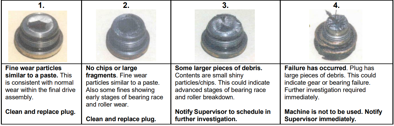
MAGNETIC PLUGS
-
LH Front Wheel Hub
-
RATING:
-
RH Front Wheel Hub
-
RATING:
-
LH Final Drive
-
RATING:
-
RH Final Drive
-
RATING:
-
BRAKES
-
Oil level and leaks
-
Noise
-
Service brake operation
-
Spec: Actual:
-
Secondary / emergency brake operation
-
Spec: Actual:
-
Park brake operation Spec: Actual:
-
Retarder brake operation
-
Boosters
-
Air leaks
-
Gauges and warning devices
-
Air tank drain and safety valve
-
Compressor and governor
-
Hose and pipes for correct routing, correct clamping and not rubbing
-
Sensors, controls and wiring
FRAME
-
“A” frame bearing movement
-
“Dog bone” bearing movement
-
Chassis rust or cracks
-
Hose, pipes and clamps
-
Pos 1 strut, pins and bushes and height
-
Pos 2 strut, pins and bushes and height
-
Pos 3 strut, pins and bushes and height
-
Pos 4 strut, pins and bushes and height
-
Hydraulic tank, hoses and fittings
-
Fuel tank, pipes and fittings
-
Fuel tank vent breather fitted with overflow hose and directing fluid overflow away from potential hot<br>surfaces
-
Is the JNX pressure less fuel tank breather system installed
-
Wiring harness
STEERING
-
Check steering ball joints for excessive play and/or wear<br>1) Clean all steer cylinder and tie rod ends down.<br>2) Drive truck in straight line so as not to load up steering geometry.<br>3) Check horizontal wear for the ball studs and outer bearing races in the steering linkages. Use magnetic base dial indicator and utilise two way radios to communicate with operator to cycle the steering [Refer CAT: SEPD0394]<br>Ball stud wear limits: 0 to 1.02 mm - OK<br>1.02 to 1.27 mm - schedule for change out<br>1.27 mm and above - change out ball stud.
-
-
Record Measurements
-
1
-
2
-
3
-
4
-
5
-
6
-
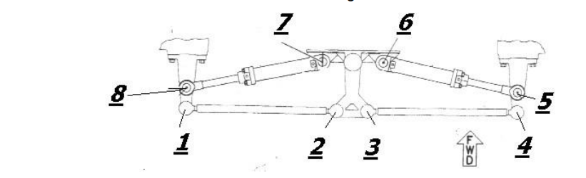
Tie Rod Checks (Caterpillar Dump Trucks)
-
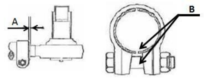
Ensure tie rod clamp positioned with aligment with one slot in tie rod (B)Refer to image (below);
-
-
Record Measurements
-
Check position of tie rod clamp from end of tie rod assembly (A) NOTE: Clamp must not exceed 6.3mm from the end of the tie rod assembly -mm
-
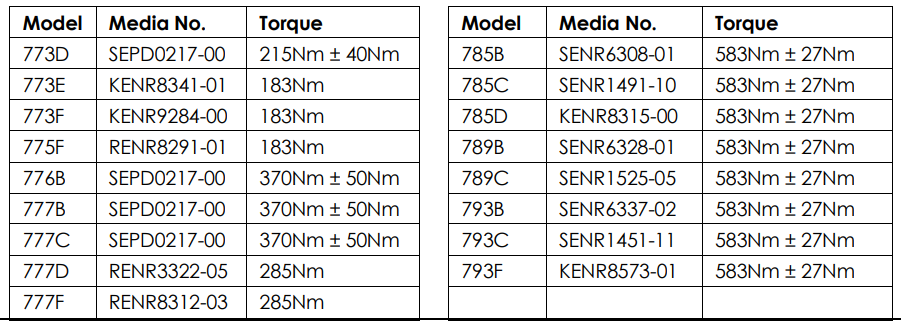
Check torque on tie rod clamp and record Nm NOTE: Refer to torque settings below. - Nm
-
-
Steering linkages for crack and damage
-
Steering cylinders and joints for crack and damage
-
Steering leaks
-
Hoses and pipes for correct routing, correct clamping and not rubbing
-
Control valve
-
King pins and bushes
-
Pivot pins and bushes
-
Follow up linkage
-
Steering box (if fitted)
-
Sensors and wiring
-
Noise from steering operation
-
Oil level
-
Steering system operation
-
Secondary / emergency steering system operation
CAB AND OPERATORS STATION
-
General cab condition
-
Floor, walls and roof
-
Cab mountings and bolts
-
All cab wiring
-
Seat belt – retainer and operation
-
Seats and arm rests – suspension and adjustment
-
Windows and rubber
-
Rear Cab Glass - Mesh guard fitted - CAT 789 Model ONLY
-
Wipers and washers
-
Doors, handles, seals and locks
-
Mirrors and mounting
-
Is the fire suppression auto shutdown enabled
-
What is the delay of the fire suppression auto shutdown
-
Air con controls and operation
-
Heater core, controls, hoses and operation
-
Access ladders and walkways
-
Horn and interior light
-
Alarms and warning lights, gauges and switches
-
Body up reverse inhibitor
-
Reverse alarm
-
Park brake alarm
-
Raised body alarm
-
Operation of all external lights
-
Two way radio and aerial (list model)
-
AM, FM radio and aerial
-
Operation of all emergency stops – cab and ground level
-
Cab has had full detail
-
Pre-start checklist booklet
-
Operator manual in the cab
-
Equipment height label installed showing normal and extended equipment heights
-
Breathsafe installed and operating correctly
WATER MODULE (IF FITTED)
-
Pump control
-
Sprays and spray bars
-
Pump, motor and hoses
-
Tank internal and external for rust
-
Tank internal for cracks and broken baffles
-
Cracks or dents
-
Foam system
-
Cannon operating correctly
-
Screw in hoses etc
SERVICE MODULE (IF FITTED)
-
Compressor mounts condition
-
All hydraulic pumps, motor and hoses and fitting for leaks / damage
-
Hose reels for leaks / damage
-
Compressor oil level
-
Water traps and filters
-
Service arm locking mechanism operating correctly
-
Service arm pivot points are free and moving correclty
-
All hoses have stoppables installed
GENERAL
-
Fire suppression
-
- Inspection current and charged
-
Hand held extinguishers
-
Inspection current and charged
-
Sizes =
-
Number =
-
Fire suppression strikers – cab and ground level
-
ISOLATION:<br>Starter motor isolation ground level – (YELLOW)<br>Battery isolation ground level – (RED)<br>Capable of being locked out
-
Jump start receptacle
-
Quick fill (service centre)
-
Battery and terminal condition
-
Paint condition
-
Accident damage
-
ROPS or FOPS fitted and condition
-
Fenders
-
Handrails
-
Access and egress
-
Emergency gate function (latching mechanism /
-
swing / alignment & damage)
-
Asset ID visible
-
Call sign identification visible on 4 sides
-
Flashing/rotating lights
-
Clearance labels – maximum and travelling
-
Safety guards
-
Collision avoidance
-
Wheel chocks
-
Pressure vessel compliance
-
Tyre and rim register
-
Fuel level
TYRES
TYRE Position
-
Make
-
Tread Pattern
-
Tyre Size
-
Serial Number
-
Wheel Nuts Torqued (Spec.)
-
OTD (mm)
-
RTD (mm) In
-
RTD (mm) out
-
% Estimate Wear Life Remaining
undefined
-
-
Tyre condition
-
Valve stems and guards
-
Studs, cleats and wheel nuts
-
Lock rings and jewellery
RIMS
-
RIM Position
-
Make
-
Serial Number
-
Build Date
-
Size
-
RIM UNIQUE ID
-
LAST NDT DATE
-
COPY OF LAST NDT CERTIFICATES SUPPLIED
CHASSIS CRACK INSPECTION
-
Details
-
Notes: - Inspect all coloured areas for racks - clean as required
- All non repaired cracks to be marked a crack ends and dated using paint marker
Front Strut Mounting Castings –check weld section and flanges
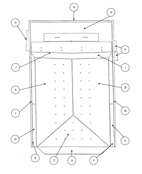
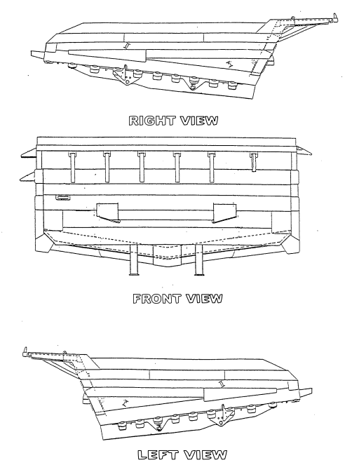
BODY
-
Body pads, shimming and mount bolts
-
Body down indicator
-
Body up retaining pins
-
Body up safety sling fitted and serviceable
-
Fitment and condition of rock ejectors
-
TPMS operation
-
Body pivot bearings for excessive movement
-
Lift cylinders, pins, bushes and retainers
-
Pipes and hoses
-
Body liners
-
Hungry boards
-
Head board
-
Cracks or dents
-
-
-
A Left Floor
-
B Right Floor
-
C Dove Tail
-
D Rear Extension
-
E Left Side Wall
-
F Right Side Wall
-
G Left Wall to Floor Bevel
-
H Right Wall to Floor Bevel
-
I Front Wall to Floor Bevel
-
J Front Wall
-
J Headboard
-
L Left Hungry Board
-
M Right Hungry Board
-
N Headboard Spill Guard
-
O Left Hand Rock Deflector
-
P Right Hand Rock Deflector
SIGN OFF
-
Prepared by
-
Fitter Signature
-
DATE AND TIME


