


Title Page
-
Business Unit
-
Conducted on
-
Customer Name
-
Project Name
-
Project Number
-
Prepared by
-
Location
-
Technician Name
Untitled Page
Pre-Work Safety
-
Confirm power is shut off at the breaker
-
Veriify voltage tester is working using a known energized source
-
Test wires with a non-contact voltage tester prior to touching
-
Confirm the amperage ratings match on the cable, circuit breaker and receptacle (15 amp circuit breakers and receptacles require 14 gauge cable and 20 amp breakers and receptacles use 12 gauge cable. 12 gauge cable can also be used on 15 amp circuits)
-
Ensure the installer is working from the most recent and valid version of the electrical code
-
Verify the outlet being installed is tamper resistant (TR)
-
The receptacle box is not recessed more than 1/4 inch behind the finished wall
Required Tools
-
Non-contact voltage tester
Cable ripper
Cutting pliers or utility knife
Wire strippers
Wire connectors
Needle-nose pliers
Screwdrivers
Scrap NM cable (as needed)
Outlet receptacle with cover plate
Instructions
Prepare the cables
-
-
Outer sheathing of the NM cable should extend no more than 1" in to the back of the box
-
Cut away the paper inside the jacket
-
Conducting wires are cut to no more than 7" in length
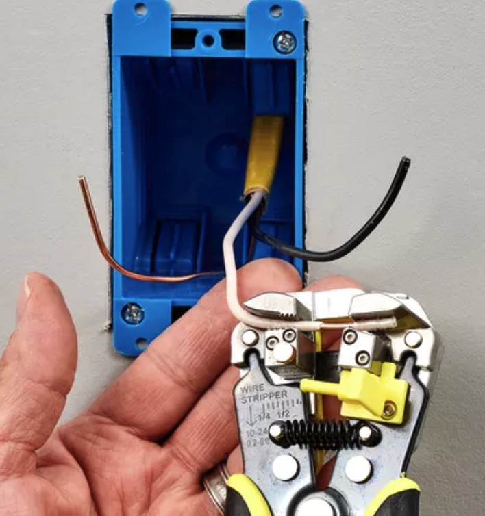
Strip the wires
-
-
Using the wire stripers, strip away 1/2" to 3/4" of insulation from the end of each insulated wire
-
Verify the ends are free from nicks or scratches. If they are, cut them back and strip off additional insulation
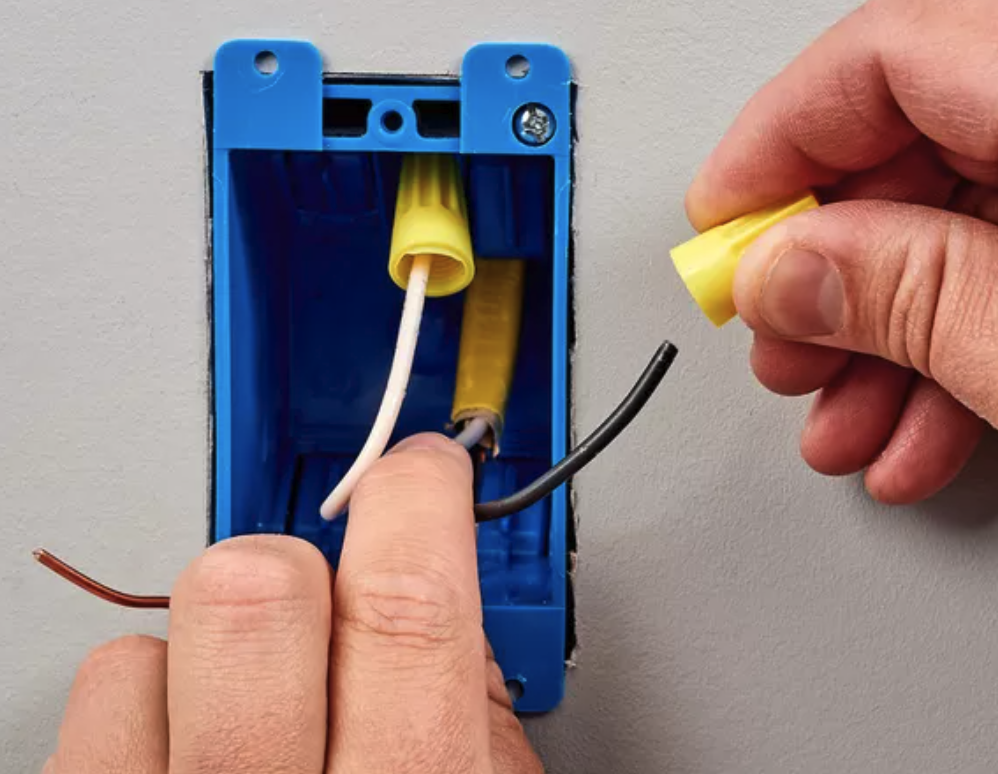
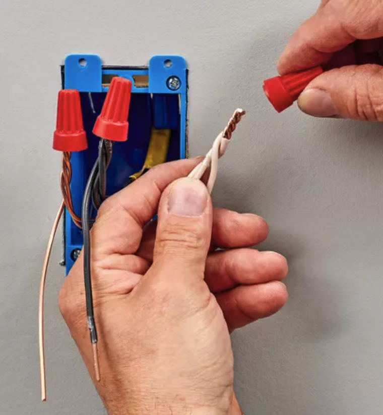
Attach pigtail wires to circuit wires
-
Pigtails required?
-
-
Verify pigtail is the same gauge as the circuit cable
-
Cut 6" length of each type of wire in the cable
-
Strip one end 1/2" and the other end 3/4"
-
Curl the 3/4" end in the shape of a hook using needle-nose pliers
-
Join the 1/2" exposed end of the bare copper (or green insulated) pigtail to the ground wires in the circuit cables using a wire connector
-
Join the 1/2" exposed end of the white (neutral) pigtail to the white wire in the circuit cable using a wire connector
-
Join the 1/2" exposed end of the black (hot) pigtail to the black wire in the circuit cable using a wire connector
-
If the electrical box is metal, install an additional grounding pigtail and connect it to the ground screw on the box
Connect the ground wire to the receptacle
-
-
Fit the hook end of the ground wire around the ground screw of the receptacle
-
The wire should hook around in a clockwise orientation
-
Use needle-nose pliers to squeeze the hook closed around the threaded shank of the screw
-
Tighten the ground screw with a screw driver
-
The hook should fit snugly around the shank of the screw
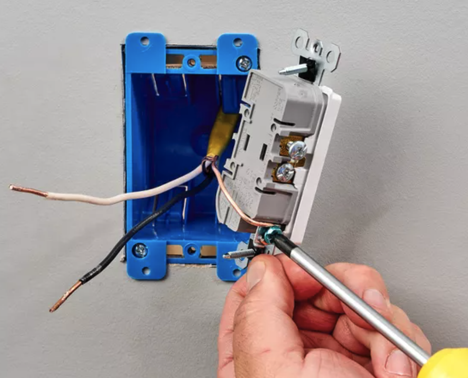
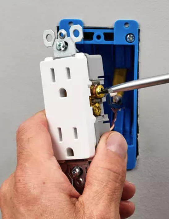
Attach the neutral and hot wires to the receptacle
-
-
Connect the white neutral wire (or pigtail) to one of the silver (neutral) screw terminals on the receptacle
-
The wire should hook around in a clockwise orientation
-
The insulation should just touch the screw terminal
-
Connect the black (hot) wire or pigtail to one of the brass (hot) screw terminals on the receptacle
-
The wire should hook around in a clockwise orientation
-
The insulation should just touch the screw terminal
-
For standard outlet wiring, the white neutral wire can go on either of the two silver terminals, since they are interchangeable. Likewise, the black hot wire can go on either brass screw terminal.
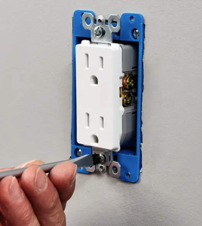
Attach the receptacle to the box
-
-
Confirm all wiring connections are secure by gently tugging on each wire
-
Reconnect and retighten any loose wires
-
Carefully tuck the wires in to the box
-
Ensure there are no sharp kinks in the wire
-
Press the receptacle's mounting straps against the top and bottom of the box
-
Attach the receptacle to the box using the screws provided. Do not overtighten
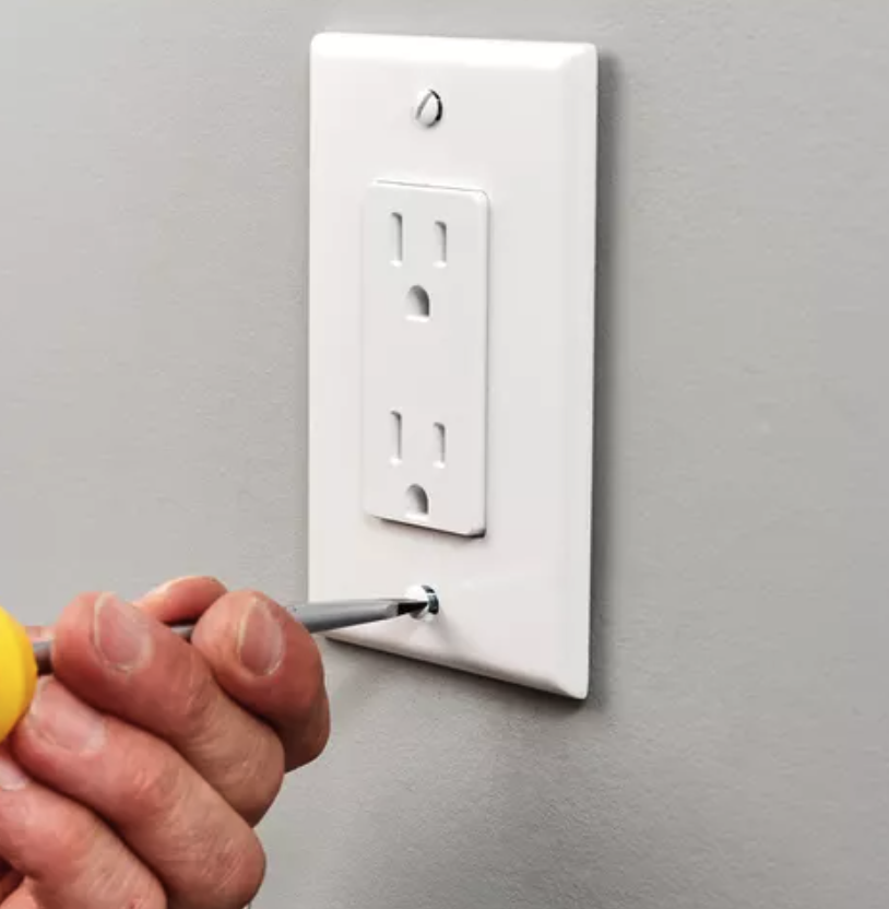
Attach faceplate and test
-
-
Fit the cover plate over the outlet and secure it with the mounting screw
-
Restore power to the circuit by switching on the circuit breaker
-
Using a plug in receptacle tester, confirm the receptacle has power, is wired correctly and is grounded properly.
Findings
-
Overall score
-
Auditor's notes
-
Auditor's signature
-
Technicians signature


