


Information
-
Site conducted
-
Customer
-
Site Address
-
Post Code
-
Conducted on
-
Inspected By
-
Item Location
Preventative Maintenance and Safety Check
-
Control Type
- Controlled Entry, Free Exit
- Controlled entry and exit
Standard Preventative Maintenance
Gates
-
Gate Location
-
Gate Direction
-
Users and others who may encounter gate
- No untrained persons present
- Untrained persons could be present
- High number of vulnerable persons present
-
Ensure the gates comply with BS EN 12453 and the current machinery directive. If not then the equipment must be isolated until further works are carried out
-
Please provide photographs
-
Height of gate (mm)
-
Width of each leaf (mm)
-
Motor Type
-
Number of motors
-
Motor voltage
-
Manufacturer of automation system
-
Model of Motors
-
Model of control unit
-
Photocells fitted?
-
Brief description of how photocells can be added E.G wireless, cabled etc
-
Take a picture
-
Safety edges fitted?
-
Brief description of number, sizes and type of edges required including wireless systems, end or through edges. If entrapment risk switch off system
-
Take a picture
-
manual override key available?
-
Type of override key required? key box required?
-
Do the gates move easily without great effort
-
Investigate and report
-
Take a photo
-
Inspect the condition of the motor spline and collar
-
Add media
-
Collar type
-
Lubricate hinges and inspect for wear
-
More info
-
Add media
-
Loops fitted
-
Mega test loops if applicable
Wherever Possible safe design has been used over application of safety devices to eliminate hazards:
-
Safe design hinge area?
-
Fixed guards and fences?
-
Anti-climb precautions taken with fences and guards?
Structural integrity (EHSR 1.3.1, 1.3.2, 1.3.6) The following are adequate to support at least 2 x the forces applied by the automation and expected wind loading's without permanent distortion:
-
Foundations?
-
Fixings
-
Brackets
-
Support Structures
-
Posts
-
Supporting masonry
-
Gate leaf structure
The following are adequate to support the gate and the forces applied by the automation and expected wind loading's and protect it from singe component failure hazards:
-
Hinges
-
Travel stops
Equipment on gate?
-
Loops?
-
Number? free exit? safety?
-
Keypad?
-
Make/Model
-
Add media
-
Intercom?
-
Make/Model
-
Add media
-
Remote Receiver
-
Make /Model
-
Add media
-
Warning Lights Fitted?
Safety Assessment
-
Check safety systems are compliant, shared pedestrian use, internal key pad, Push to exit buttons, Break glass, Gaps and External Beams.
-
All checks carried out to manufacturers instructions?<br>
-
Supply Details
Electrical Checks
-
Does the electrical installation appear sound and correct
-
Are all cable joints correct and well terminated <br>
-
Are all control boxes and junction boxes free from any water ingress
Force Test
-
Has a Force test been carried out?
-
average F DYN (N) result for bottom edge of gate using 500mm tool
-
average T DYN (S) result for bottom edge of gate using 500mm tool
-
average F END (N) result for bottom edge of gate using 500mm tool
-
average F DYN (N) result at centre of gate or 2500mm from floor using 500mm tool
-
average T DYN (S) result at centre of gate or 2500mm from floor using 500mm tool
-
average F END (S) result at centre of gate or 2500mm from floor using 500mm tool
-
average F DYN (N) result at top or the gate using 500mm tool
-
average T DYN (S) result at the top of the gate using 500mm tool
-
average F END(N) result at top or the gate using 500mm tool
-
50mm tool average F DYN (N)
-
50mm tool average T DYN (S)
-
50mm tool average F DYN (N)
-
Has the gate passed the force test
Installation diagram and assessment
-
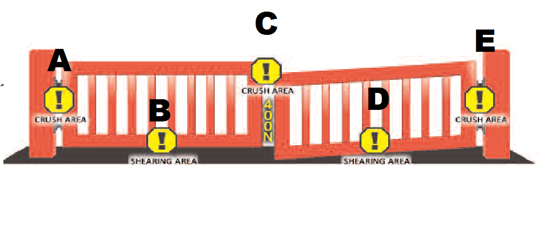
Identify (if relevant) potential hazards at points labelled on diagram, and comment below
-
Include diagram from library
-
A - Crushing area at leading leaf hinge point
-
B - Shearing & crushing area at rear of leading leaf
-
C - Crushing area in between closing edge on gate leaves
-
D - Shearing & crushing area at rear of leading leaf
-
E - Crushing area at leading leaf hinge point
-
Recommendations
-
Additional photographs
Overall condition / Performance of system / additional information.
-
Defects? (list any defects that need attention)
-
Recommendations (list items that you would recommend
-
Engineer
-
Client representative


 2022")
 2022")