


Title Page
-
customers name
-
Site name
-
Location
-
System Type/Types
- Grade 2E Intruder - Local Audible
- Grade 2 ( Keyolder Only)
- Grade 2 Policed
- Grade 3 intruder
- NCP 104 CCTV Install
- NCP 109 Access Control Install
-
NSI Cert No's:
-
NSI Cert issue date
-
Date of install
-
Typically for new installs - should have been issued with 30 days of handover date
non domestic : Silver = S Gold = G
Domestic : Silver = R Gold = D
Install
-
Are you completing A Technical Inspection Today
- Yes
- No
-
System Type
- Intruder
- CCTV
- Access
- PMV Intruder
INTRUDER tech Audit
Day Mode Tests
-
Engineer to Place system on test with ARC
-
engineer to remove mains supply wait for alert - Clause: BS EN 50131-1/17:9.2b POWER SUPPLIES Q1
- Compliant
- Non-Compliant
- N/A
-
Check Fuse used adequete <br>Clause: TS50131-7/10:H.21 <br> POWER SUPPLIES Q5
-
Unswitched Spur ( g2/3/4) or Plug with captive cover ( G2 only)<br>Clause: TS50131-7/10:H.21 <br> POWER SUPPLIES Q5
-
Remove Panel lid in Day mode - does local alarm and/or ATS send signal to ARC if PD6662<br>Clause BS EN 50131-1/17:8.7.2<br>TAMPER AND SUBSTITUTION DETECTION _ TAMPER DETECTION Q4
-
Panic Buttons Fitted
-
Remove lid ensure Tamper signalled not PA so as to create a confirmed alarm<br>Clause: BS 8243-2010+A!-2014 H.3.2 (Table H.2 b)<br>
-
PA signal sent to ARC - PD6662<br>Clause BS EN 50131-1/17:8.1.2<br> HOLD-UP DEVICES Q1
-
PAB is not a dual action device<br>Clause BS EN 50131-1/17:8.1.2<br> HOLD-UP DEVICES Q2
Engineer Mode Tests
-
Place Alarm in Engineer Mode
-
Entry to Level 3 engineer menu restricted exclusions allowed: Note on completion cert / signal sent to arc stating engineer on site + accompanied by local alert)<br>BS EN 50131-1:2006+A2:2017 8.3.1 <br> OPERATIONS - ACCESS LEVELS - Q2
-
Carry out Current draw tests - compare to comissioning or take note <br>Clause: BS 9263:2016 Table A.1<br> DOCUMENTATION Q8
-
Battery correct size - Calculations done (12hrs G2 and G3 if signalling mains fail - 24hrs if not) - <br>Clause: PD 6662/17:Annex B.2 ( Table B1)<br> POWER SUPPLIES Q5
-
Check workmanship - cables Secure & Neat and labelled <br>BS EN 50131-1/17: 8.3<br> OPERATIONS - GENERAL - Q1
-
Battery Dated at time of install<br>Clause: BS 9263:2016 Table A.1<br>DOCUMENTATION Q8
-
removal of holdoff voltage leads to external sounder activation<br>Clause : BS EN 50131-4:5.6.3.4b<br> WARNING DEVICES - SELF-POWERED - Q4
-
Mains and LV cables segregated ( not through same holes) <br>TS 50131-7/10: 7.3.3.1<br>INTERCONNECTIONS - Q3
-
check ATS Path fail monitoring wired to control panel for local alert/prevents setting if in fault<br>BS EN 50131-1/17: 8.5.1 (tables 1 and Table 4) and BS EN 50136-1:2012+A1:2018 (TABLE 5)<br> FAULTS AND OTHER FUNCTIONS - Transmission path faults - Q1
-
Mains Cable secured in Panel<br>TS 50131-7/10: 7.3.3.1<br> INTERCONNECTIONS - Q4
-
If AT Path signalling - drop 1 path and check signal to ARC<br>BS EN 50136‑1:2012+A1:2018 ( as per Table 5) <br> FAULTS AND OTHER FUNCTIONS - Transmission path faults - Q1
-
CIE Altered from manufacturers design (ie lugs cut off)<br>BS EN50131-6-2017 3.1.12 <br> System requirements - mandatory and additional functions
-
Any additional PSU's fitted
-
PSU Graded as per rest of system<br>BS EN 50131-1/17: 6<br>SYSTEM REQUIREMENTS - GRADING - Q1
-
Repeat current/battery tests same timescales apply as per main system grade<br>Clause: PD 6662/17:Annex B.2 ( Table B1)<br> POWER SUPPLIES Q5
-
PSU TAMPERED<br>BS EN 50131-1:2006+a2:2017 8.7.2 (Table 11) <br> TAMPER AND SUBSTITUTION DETECTION _ TAMPER DETECTION Q4
-
PSU BATTERY FAULT<br>BS EN 50131-6-2017 (TC) 4.3.1 TABLE 2<br> Interconnections
-
PSU MAIN FAULT<br>BS EN 50131-6-2017 (TC) 4.3.1 TABLE 2<br> Interconnections
Programming Checks
-
completion of setting (shunt/pts/FExit DC) (if on police response)<br>BS 8243: 6.3<br> Setting and unsetting - Completion of setting using a digital key (6.4.5) - Q1
-
Opening the Entry door does not start the entry timer ( can accept alternative if not practical to fit contact to door ie fully glass)<br>Clause: BS EN 50131-1/17: 8.3.7<br> SETTING AMD UNSETTING - GENERAL REQUIREMENTS ASSOCIATED WITH ENTRY ROUTES - Q1
-
Entry Timer <45s & Matches Specification<br>Clause: BS EN 50131-1/17: 8.3.8.2<br>SETTING AMD UNSETTING - GENERAL REQUIREMENTS ASSOCIATED WITH ENTRY ROUTES - Q2
-
Completion of setting can be heard from outside property<br>TS 50131-7/10: 7.3.5<br> SETTING AND UNSETTING - SETTING INDICATIONS -Q1
-
Bell Duration <15min<br>BS EN 50131-4: 5.1.3<br> Warning Devices - External and Internal warning devices - Q2
-
Bell Delay >1s ( unless stated on spec) <br>BS EN 50131-4 5.1.3<br>Warning Devices - External and Internal warning devices - Q1
-
Code locked on Entry or confirmation disabled<br>Clause: BS 8243: 6.4.5<br> SETTING AND UNSETTING - Completion of unsetting using a digital key (6.4.5) - Q4
-
Engineer Reset (confirmed Alarm)<br>Clause: BS 8243-2006+A2-2013 10.1<br> OPERATION - RESTORE - Q3
-
Mis-operation/Abort /set/unset signal not programmed - Police response<br>BS 8243 6.2b<br> System Requirements - Facilities to aid filtering of intruder alarms - Q1
-
Zone Programming check - Matches "as fitted Specification and Device type matches type fitted<br>Clause: TS 50131-1/10 - 10.7<br> DOCUMENTATION Q9
-
Drop out of Engineer Mode
General Installation checks
-
Full set system - if monitored check signals
-
Cables adequately supported along entire route and inside trunking etc - evidence of fire retardant clips<br>TS 50131-7/10: 7.3.3 links to IET wiring regs BS 7671:2018: section52 : clause - 521.10.202<br> INTERCONNECTIONS - Q6
-
If cables run externally are they mechanically protected<br>TS 50131-7/10: 7.3.3<br>INTERCONNECTIONS - Q7
-
mains and LV cables segregated<br>TS 50131-7/10: 7.3.3.1<br>INTERCONNECTIONS - Q2
-
joins in cable - Tampered junction Box or soldered <br>BS EN 50131-1/17: 8.7.1<br> TAMPER PROTECTION - Q3
-
Detection/CIE on ceiling tiles that can be moved<br>BS EN 50131-1/17: 8.7.1 or <br> TAMPER PROTECTION - Q4
-
Cabling below 2m - mechanically protected<br>TS 50131-7/10: 7.3.3.1<br> INTERCONNECTIONS - Q8
-
No PIRs Overlapping detection areas<br>BS 8243: 5.4.2/3 also referances BS 8243: 5.4.1.1b <br> IAS CONFIRMATION - Q9 OR Q11
-
is either the Control Panel or Keypad located outside the protected area<br>TS 50131-7/10: 7.3.2.1/2<br> SYSTEM REQUIREMENTS - SITING OF EQUIPMENT - Q1
-
Is Keypad visable from outside <br>BS 8243: 6.4.1<br> SYSTEM REQUIREMENTS - SITING OF EQUIPMENT - Q2
-
All components Same Grade or higher ( minimum as per Spec)<br>BS EN 50131-1/17: 6<br>SYSTEM REQUIREMENTS - GRADING - Q1
-
Consideration not given to the ingress of insects into PIR detectors (inadequate sealing).<br>TS 50131-7/10: H.6 <br>DETECTION DEVICES COMMON - PIR DETECTORS - Q2
Documentation
-
Certificate issued with 30 days<br>Clause : NSI Regulation: A.3<br> Documentation Q1
-
Customer Signature on handover Certificate<br>Clause: TS 50131-1/10 - 10.6<br> DOCUMENTATION Q9
-
Locations on "as fitted" Specification and on site match<br>Clause: TS 50131-1/10 - 10.7<br> DOCUMENTATION Q9
-
Customer Advice about Remote Setting/unsetting - following should be on spec:<br>“IMPORTANT<br>If using a remote device to remotely set/unset your intruder alarm system, your attention is drawn to the fact that whenever a premises is unattended but its intruder alarm system(s) is (are) not fully set, any related insurance cover might be inoperative. For advice on this matter, it is recommended that you consult your insurer(s).”<br>Clause : PD6662-2017-TC A.5.4 <br>Iwam Section: DOCUMNETATION - Q10
Extra Requirements for wireless and Grade 3
-
Additional checks for Grade 2 wireless & Grade 3
Grade 3 compliance
-
Back Tampers enabled on all devices inc keypads/Expanders/Warning devices etc<br>Clause: BS EN 50131-1/17: 8.7.2<br> TAMPER AND SUBSTITUTION DETECTION - TAMPER DETECTION - Q6
-
Back Tampers enabled on all detection devices<br>Clause: BS EN 50131-1/17: 8.7.2 & BS EN/TS 50131-2-X<br>: DETECTION DEVICES GENERAL - TAMPER - Q3
-
External Sounder has Fault Reporting Enabled (loss of remote power/Tamper)<br>Clause : BS EN 50131-4:5.6.3.4b<br> WARNING DEVICES - SELF-POWERED - Q2
-
Sounder bell wire trigger monitoring <br>Clause: BS EN 50131-4.2019 5.1.3 ( Table 1) <br> WARNING DEVICES - INTERNAL AND EXTERNAL WARNING DEVICES -Q4
-
Contacts have substitution enabled<br>Clause: BS EN 50131-1/17: 8.7.4<br> TAMPER AND SUBSTITUTION DETECTION - Substitution - Q2
-
Masking Enabled on all Detectors<br>Clause: BS EN 50131-1:2006+A2:2017 8.2.1 <br> FAULTS AND OTHER FUNCTIONS - MASKING - Q1
-
LEDs Disabled other than when in Walktest<br>Clause: BS EN50131-1:2006+A2:2017 8.3.12<br> OPERATIONS - TEST - Q2
-
User and Engineer codes 5 or more digits ( 100,000) or greater combination<br>Clause: BS EN50131-1:2006+A2:2017 8.3.2<br> SETTING AND UNSETTING - AUTHORISATION AND UNSETTING - Q2
-
Mains Fail transmitted to ARC seperately to General fault or 24hr battery backup<br>BS EN50131-1:2006+A2:2017 9.2 (table 22)<br> POWER SUPPLIES - Q5
-
Tamper set to Engineer Reset<br>Clause: BS 8243-2006+A2-2013 10.1<br> OPERATION - RESTORE - Q3
-
Tamper Transmitted<br>BS EN50131-1:2006+A2:2017 8.4.3 ( as per table 7)<br> Processing and Indication - Processing - Q3
-
General Fault Transmitted<br>BS EN50131-1:2006+A2:2017 8.4.4 ( as per table 7)<br>Processing and Indication - Processing - Q3
Wireless Additional Checks
-
Back Tampers enabled on all Controls IE: keypads/Expanders/Sounders<br>Clause: BS EN 50131-1/17: 8.7.2<br> TAMPER AND SUBSTITUTION DETECTION - TAMPER DETECTION - Q5
-
Back Tampers enabled on all detection devices<br>Clause: BS EN 50131-1/17: 8.7.2 & BS EN/TS 50131-2-X<br> DETECTION DEVICES GENERAL - TAMPER - Q3
-
Setting period not less than 30s if set remotely (app/fob) and that an audiable sound can be heard throughout the building.<br>PD 6662/17: A5(c)<br> SETTING AND UNSETTING - REMOTE SETTING AND UNSETTING - Q3
-
Applicable if on police response
Texecom :- Global options - configuration - option 58 - Should be timed ( exit time needs to be set to min 30 as well)
Castle/pyronix: - App setting time
CCTV tech Audit
Design Documentation
-
Drawings/photographs/notes of the proposed locations of Cameras and System components including details of targets and location of risk<br>Clause: NCP 104/17: 5<br> Documentation requiremenst and system design - Q4 & Q6
The design/specification document does not contain the following: NCP 104/17: 6.1 - 6.15 as required by (BS EN 62676-4 Clause 5) Iwam section- Documentation requirements and system design - Q11- Q44
-
Q11 - Intended purpose : <br>NCP 104/17: 6.1
-
Q12 - General description of areas under surveillance : <br>NCP 104/17: 6.2
-
Q13 - details of intended target/purpose of image captured IE: image catagory) <br>NCP 104/17: 6.3
-
Q14 - image quality requirements for live, playback and export images; tracking and detecting targets; generating alerts/messages. <br>NCP 104/17: 6.4
-
Q18 - details of monitoring, storage and data retention requirements<br>NCP 104/17: 6.8
-
Q28 - System design survey signed off by customer.<br>NCP 104/17: 7
-
Q29 - Referance to GDPR and the requirement for the system to be registered with the ICO noted on customer documents ie specification<br>and specified duration fro retention of recordings not stated GDPR requirements as per ICO code of practice<br>NCP 104/17: 7.1 - - ICO Code of practice - Principle (e): Storage limitation
-
Q31 - Camera and lens information missing or incomplete.<br>NCP 104/17: 7.3
-
Q38 - Frame rate not identified for each Camera<br>NCP 104/17: 7.10
-
Q39 - Video resolution for camera/system not stated<br>NCP 104/17: 7.11
-
Q41 - Storage Calculations or assumption made to cover intended recording durations<br>NCP 104/17: 7.12
-
Q44 - When using customer supplied network or connectivity to External sources - no network requirements stated<br>NCP 104/17: 7.19
-
NOTE 1:
Area: Area of Coverage by Camera
Purpose: (Video Cameras )
Identification : 120% of screen height
Recognition : 50% of screen height
Detection : 10% of screen height
Crowd control : 5% of screen height
Purpose: (Thermal cameras)
Identification : ability to describe the object in details (a man with a hat, a deer, a Jeep)
Recognition : ability to classify the object class (animal, human, vehicle, boat)
Detection : ability to distinguish an object from the background
Location: Pysical Install point
Height: Approximately 4 metres.
Resolution: ie : Full HD 1080p
Frame Rate: ie : Approximately 15 images per second / VMD (video motion detection) recording.
Duration: Approximately 30 day’s storage. -
NOTE 2
:1) Make sure people know they’re being recorded
Transparency is a core principle of the GDPR.
2) You must tell people when you’re collecting their personal information to give them the opportunity to exercise their data subject rights.
These rights enable individuals to access the personal data organisations store on them and to challenge the way their information is used.
You can make sure people are aware you’re recording them by posting signs that say CCTV is in operation.
If you’re using CCTV to monitor employees, you should also explain in your privacy policy that they are being recorded.
Most organisations have a retention period for CCTV footage, simply because it’s too impractical to keep the information indefinitely.
Physical tapes will soon stack up and digital files will eat up memory. However, you must now be more systematic about how long you keep recordings.
The Regulation states that you can only store information for as long as it’s necessary for the purpose for which it was collected, and you must outline that time frame before you start processing.
You should therefore establish a system to make sure you delete information once the data retention deadline passes.
As for how long ‘as long as necessary’ is, that depends entirely on why you are collecting the information. However, it’s unlikely that you will need to keep the data for more than a week or two. -
NOTE 3
Where it has not been possible or it is not considered either practicable or necessary to carry out a site survey, (for example the system design has been provided by the user or where the property has not been built) this fact and any limitations that may affect the design of the system, (for example, expected lux levels, proximity of adjacent properties, changes in internal layout) must be made in clear in the system design documentation.
Installation checks
Imaging and sensing
-
Images Clear and Focused Day and Night<br>Clause: NCP 104/17: 7.8<br> Imaging and sensing - Q7
Video and Audio
-
Video resolution/Frame rates not as stated in Design Specification<br>Clause: NCP 104/17: 7.11<br> Video and Audio - Q2 & 3
Data Handling
-
The system storage does not meet User requirements/specification<br>Clause: NCP 104/17: 7.12<br>data handling - Q1
-
System set to Auto adjust DST or no access via user menu to adjust manaully<br>Clause: NCP 104/17: 7.15<br>data handling - Q5
Networks
-
Access to system applications and operating systems are not restricted to authorised individuals via means of password or similar.<br>Clause: NCP 104/17: 7.20<br>Networks - Q2
-
If using cat6 or higher ( cables not supported as per manufacturers instructions - ie cable ties to tight / tight or kinked bends)<br>Clause: NCP 104/17: 7.27<br>Networks - Q4
-
network cable runs not less than 100m (IP Systems) - Unless means of boosting signal also installed ie POE injector/extender ( note some Samsung cameras now have this feature built into them <br>Clause: NCP 104/17: 7.27<br>Networks - Q4
Ancillaries
-
Control Equipment/Recording equipment not fitted in secure location<br>Clause: NCP 104/17: 7.21 / BS EN 62676-4 Clause 6.11)<br> Ancillaries - Q2
-
Cameras are not Securely Mounted / Mounted on movable object that could lead to an altered field of view ( ie unsecured ceiling tile)<br>Clause: NCP 104/17: 7.21 / BS EN 62676-4 Clause 6.11)<br> Ancillaries - Q2
-
Cables are not mechanically Supported/ Protected so as to mitigate against tampering/fault<br>Clause: NCP 104/17: 7.27<br>Ancillaries - Q4
-
Masts, towers, brackets and/or supports not stable and secure and/or fit for purpose<br>Clause : NCP 104/17: 7.28<br>Ancillaries - Q5
Installation
-
Power supplies not located in a secure area or positioned to prevent/deter tampering or configured to detect and report tampering.<br>Clause: NCP 104/17: 8.4<br>Installation - Q1
-
Cabling not suitably segregated, screened and insulated as required.<br>Clause: NCP 104/17: 8.5<br> Installation - Q4
-
Cables adequetly supported along entire route - Steel fixings/containment to prevent hanging cables<br>Clause: NCP 104/17: 8.5 9 (IET WIRING REGS - BS7671:2018 Section 52 : 521.10.202)<br>Installation - Q4
-
Structured cabling components all of same type and appropriate to cable type ( ie All cat5 or All cat6) not mixed<br>Clause: NCP 104/17: 8.5<br> Installation - Q7
-
Cables marked at termination points with Source information<br>Clause: NCP 104/17: 8.5<br> Installation - Q9
Install Documentation
-
Documentation - Install,Test,Comission & Handover completed as required below:
Clause: NCP 104/17: 8.5
Iwam Section : Documentation - Install,Test,Comission & Handover - Q1_ 11 -
Q1 - data cabling must at a minimum be tested for the correct wire mapping, short and open circuits, cross talk, cable length, attenuation and speed. The results of this testing must be documented.<br>Clause: NCP 104/17: 8.5
-
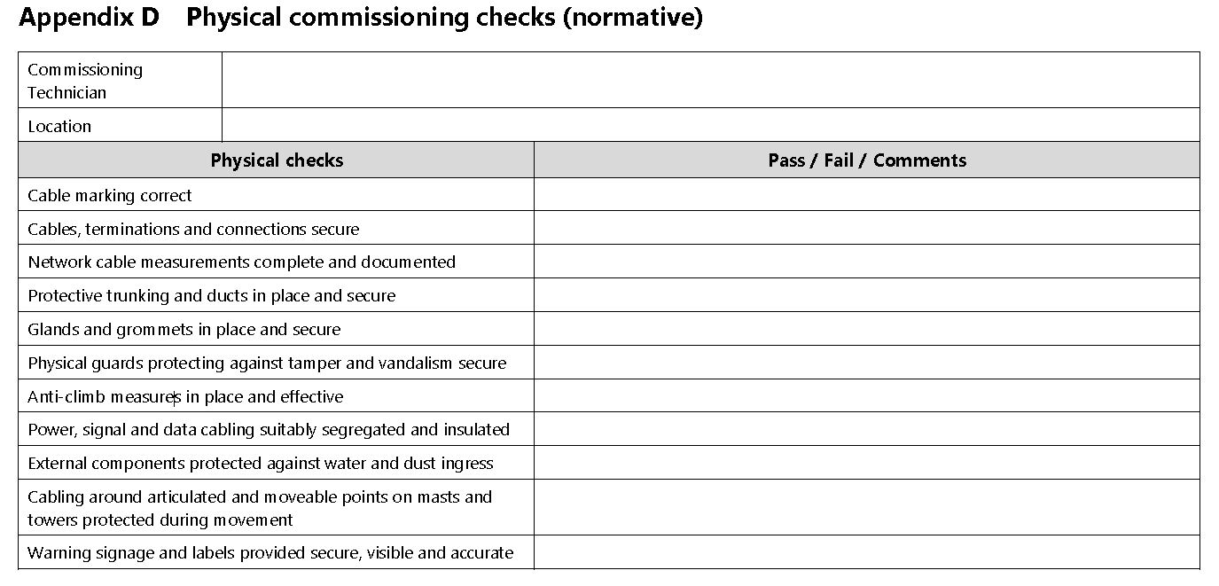
Q6 - Comissioning checklist not completed<br>NCP 104/17:9.2 Appendix D
-
see image from NCP 104
-
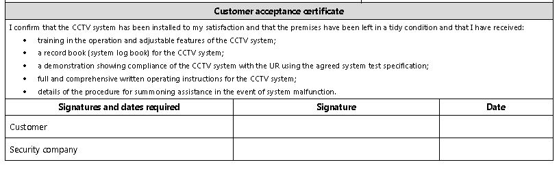
Q7 - Customer Handover document completed - <br>stating training completed & Signed as per Annex E NCP104/17
-
see image example from NCP104
-
Q9 - Customer documentation as per BS EN 62676-4 Clause 16.3).<br> "As Fitted" specification incomplete/missing <br>Clause: NCP 104/17: 10.1
-
Q9 - Customer documentation as per BS EN 62676-4 Clause 16.3).<br>Handover Snapshots taken and issued to customer/retained on file<br>Clause: NCP 104/17: 10.1
-
Q10 - Installer documentation is not a clone of Customer documentation supplied<br>Clause: NCP 104/17: 10.2
-
Q11 - Unless otherwise agreed in writing with the customer, all system accounts used by the installer must be deleted or locked and the user advised to change passwords when the system is handed over. This includes removing remote access rights to the system.<br>Clause : NCP 104/17: 9.4
ACCESS CONTROL SYSTEMS Tech Audit
Documentation
-
Survey Evidence/ Design aceptance not available <br>Clause: NCP 109: Pt 1: 4.1<br> Documentation - Q1
-
Agreement in place if using the Exisiting Customer LAN for connection of the ACU's to the Database/Software:<br>Clause: NCP 109: Pt 1: 4.1<br> Documentation - Q1
-
Identification cards not carried by staff visiting premise which must include a photograph of the bearer, their signature, the name of your company and a date of expiry.<br>Clause: NCP 109: Pt 1: 4.1<br>Documentation - Q2
-
Commissioning records do not include all of the required checks.<br>Clause: NCP 109: Pt 1: 5.1<br> Documentation - Q3
-
Required fields in 5.1 Commissioning
You must check and acknowledge the following during commissioning:
all wiring is correctly terminated;
voltage and resistance at all appropriate points of the system are correct, which must be recorded;
operation of access point hardware and of release and closure mechanisms at each access point is correct;
emergency release mechanisms at all the access points are in full working order;
operation of each reader is correct;
release time for each door is correct;
door held open signal, if specified, is present;
correct authorisation of access is verified by the input of appropriate database permissions;
access control system continues to work when mains supply disconnected (if specified). -
As fitted Document includes the below required information<br>Clause: NCP 109: Pt 1: 5.1<br> Documentation - Q4
-
5.3 Documentation
Upon completion of installation of the access control system you must produce an as-fitted document including the following information:
a) the name, address and telephone number of the controlled premises;
b) the name, address and telephone number of the customer;
c) the location and classification of each access point and the type and location of each controller and its associated hardware (for example the type of token/reader technology);
d) the type and location of power supplies;
e) power supply standby periods where relevant;
f) details of those access points which the customer has the facility to override;
g) the type and location of any warning device;
h) details and settings of any preset or adjustable controls incorporated into the system;
i) relevant documentation relating to equipment;
j) relevant documentation relating to software functions;
k) the number of keys, codes, tokens, and so on for the system provided to the customer;
l) details of the methods adopted for emergency override for safe escape.
You must agree the as-fitted document with the customer and provide the customer with a copy.
You may provide some of the information required for the as-fitted document in the form of a diagram of the installed system. -
NSI Cert issued within one month of handover<br>Clause: NSI Regulation: A.3<br> Documentation - Q5
-
System log book not supplied; no handover checklist and/or customer signature on completion certificate.<br>Clause: NCP 109: Pt 1: 5.2<br> Handover and Training - Q1
-
There is lack of evidence of appropriate training of users in<br>relation to system operation and/or producing system back-ups<br>and/or the procedure for summoning assistance.<br>Clause: NCP 109: Pt 1: 5.2<br> Handover and Training - Q2
Installation Checks
Safety Checks
-
Simulate a system failure ( downpower ACU PCB controlling door - PSU poviding lock power to remain powered if possible )
-
No means of emergency overide in event of fire ( must be for specific door and be mechanical ie not a generic software command to a master ACU)<br>Clause: NCP 109: Pt 1: 4.1<br> Safety Requirements -Q1
-
ie: thumb turn, Breakglass, keyswitch, fire alarm relay
-
Safe escape methods do not include emergency override facilities when access points fail locked under system failure conditions.<br>Clause: NCP 109: Pt 1: 4.2.3<br>Safety Requirements - Q2
-
Operating/Supplied Voltage clearly marked on the equipment housings<br>Clause: NCP 109: Pt 1: 4.2.4<br>Safety Requirements - Q3
-
No key override to a critical door, with the key kept in a safe place outside the controlled door/area where specified, in case of a system failure<br>Clause : NCP 109: Pt 1: 4.2.3<br>Access Point hardware - Q11
-
re-instate system to normal conditions
Power supplys
-
Power supply units located in controlled areas and secure when power fail unlocked operates.<br>Clause : NCP 109: Pt 1: 4.2.4<br>Power Supplies - Q3
-
Ease of access for maintenance <br>Clause: NCP 109: Pt 1: 4.3<br>Control Equipment - Q1
-
Mains power is not permanently connected. ( NOT plug and socket )<br>Clause : NCP 109: Pt 1: 4.2.4<br>Power Supplies - Q5
-
ELV and Mains Cables enter AC Equipment through Same holes<br>Clause : NCP 109: Pt 1: 4.2.4<br>Power supplies - Q6
-
Is there a Battery Back up ?
-
Remove Mains Power to ACU/Lock
-
Battery Capable of supporting System for specified time<br>Clause : NCP 109: Pt 1: 4.2.4<br>Power Supplies - Q7
-
Current mains disconnected x specified standby time = quiensent standby
Current under load ( locks engaging) x 25% low traffic (Flats)
50% medium ( school) = Alarm
75% High (Large Office)
Alarm Current + Quiesent Current = Total battery capacity required
Equipment Installtion
-
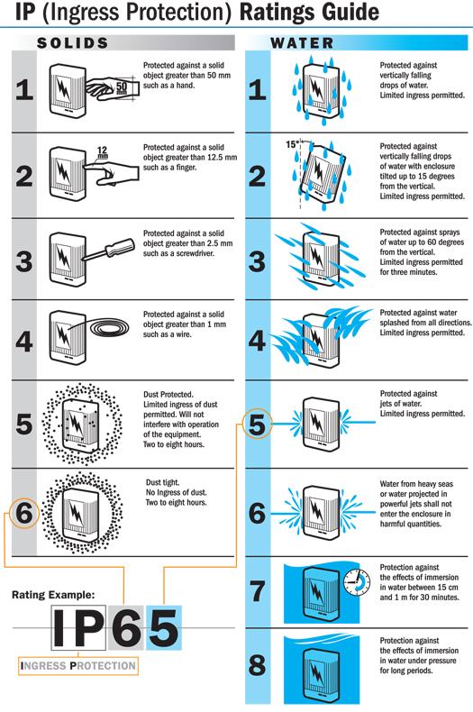
Equipment Used suitable for environment its situated in (IE correct IP rating) <br>Clause: NCP 109: Pt 1: 4.2 Referances ( BS EN 60529 ) <br>Environmental Precautions - Q2
-
IP rating Guide
-
There is no indication for access granted @ reader location<br>NCP 109: Pt 1: 4.2.2<br>Reader Functions/Indications - Q1
-
There is no means of tamper detection/Prevention from the unsecure side if lock control can be accessed from the unscure side: <br>Clause: NCP 109: Pt 1: 4.2.2<br>Reader Functions/Indications - Q3
-
for Example lock relay can be accessed in a stand alone keypad or external entry phone panel with no means of preventing easy access.
-
Door does not re-lock if not used within pre-determined entry time<br>Clause: NCP 109: Pt 1: 4.2.2<br>Reader Functions/Indications - Q5
-
Readers securely mounted/next to Door/At suitable height for ALL user icluding those with disability<br>Clause: NCP 109: Pt 1: 4.2.2<br>Mounting Readers - Q1-3
-
The environment (including corrosion, vibration and/or physical<br>abuse) has adversely affected the access point hardware.<br>Clause : NCP 109: Pt 1: 4.2.3<br>Access Point hardware - Q3
-
Door Closing devices cause Heavy impact on the components of the<br>access control system.<br>Clause : NCP 109: Pt 1: 4.2.3<br>Access Point hardware - Q7
-
The control equipment is not protected against unauthorised<br>interference with the system database or computer software (for<br>example system default passwords have not been changed/ passwords not used)<br>Clause: NCP 109: Pt 1: 4.3<br>Security Requirements - Q2
Cabling
-
Cables not installed within controlled areas (except where it is impractical to do so)<br>Clause: NCP 109: Pt 1: 4.2.5.1<br> Cable Installation - Q1
-
Cables installed outside controlled areas are not protected by<br>suitable conduit, trunking, or armour.<br>Clause: NCP 109: Pt 1: 4.2.5.1<br> Cable Installation - Q2
-
Cables exposed to possible mechanical damage or tampering are<br>not protected by suitable conduit, trunking, or armour.<br>Clause: NCP 109: Pt 1: 4.2.5.1<br>Cable Installation - Q3
-
External cabling Protected via mechanical protection<br>Clause: NCP 109: Pt 1: 4.2.5.1<br>Cable Installation - Q4
-
Cables are not adequately supported and/or their installation is<br>not to good working practice.<br>Clause: NCP 109: Pt 1: 4.2.5.1 Referances (IET WIRING REGS - BS7671:2018 Section 52 : 521.10.202)<br>Cable Installation - Q5
-
Cable Joints are not not made in suitable junction<br>boxes using either soldered, crimped, or screw-terminals.<br>Clause: NCP 109: Pt 1: 4.2.5.1<br> Cable Installation - Q6
-
LV and Mains Cables Segregated<br>Clause: NCP 109: Pt 1: 4.2.5.1<br>Cable Installation - Q7
-
Correct cable type used for Readers & 485/232 data lines as per manufacturer recommendations <br>Clause : NCP 109: Pt 1: 4.2.5.2<br>Cable Installation - Q8
-
PAXTON :
Readers - are pre-wired with 5m of cable. If this needs extending then 10 core CR9540 reader cable must be used.
Installation – The maximum cable length from reader to control unit is 100m. When using reader cable over distances in excess of 25m the 12V and 0V cores should be doubled up to minimise voltage drop
RS-485 - CAT5 Screened, Screened 8 Core or 4 Core Belden.
PAC 512:
RS-485 - CAT5 or CAT6 cable
Readers - 22AWG 4-Conductor, Unshielded and Stranded (8 core for example)
TDSI : ( see cable guide in file ) however basics are
RS-485 - CAT5 Screened, Screened 8 Core or 4 Core Belden
Readers - 6 Core Belden or *8 core Screened
There should be no Un-screen cables in a TDSI access system. -
Correct cable used to ensure current/voltage mainatined at lock to ensure max holding force. ( Take reading at ACU and Lock) <br>Clause: NCP 109: Pt 1: 4.2.5.3<br> Cable Installation - Q9
-
Flexible cable loops used as required on doors<br>Clause: NCP 109: Pt 1: 4.2.3<br>Cable Installation - Q10
Testing
-
Has the engineer placed the system on test to ensure no false alarms are transmitted to the ARC for response.<br>NACP 11 7.5.14
-
Check Fuse used adequete <br>Clause: NACP 11 Clause 7.5.5a <br>I-WAM Section: POWER SUPPLIES Q5
-
engineer to remove mains supply wait for alert -<br>Clause: NACP 11 Clause 7.5.5b<br>Iwam Section : POWER SUPPLIES Q1
-
Engineer should check supply voltages on equipment whilst on standby battery<br>Clause : NACP 11 Clause 7.5.5c<br>Iwam Section : POWER SUPPLIES Q1
-
Check the operation of the tamper detection on each power supply housing<br>NACP 11 Clause 7.5.5f
-
Has the technician checked at least one tamper for correct operation through to the Keypad<br>BS9263:2016B B.2b
-
Have functional tests been carried out on detectors and warning devices<br>BS9263:2016B B.2e
-
Hold of voltage removed from warning devices<br>BS9263:2016B B.2h and BS EN 50131-4:5.6.3.4b<br>Iwam Section: WARNING DEVICES - SELF-POWERED - Q4
-
Operations of ATS paths (all paths) including local indication on single path if SP only or dual path fail if DP <br>BS9263:2016B B.2i
-
Quiescent current reading taken on all PSU's<br>BS9263:2016 Annex B.2e calls on Annex C
-
Alarm current reading taken on all PSU's<br>BS9263:2016 Annex B.2e calls on Annex C
-
Battery Calculations for all PSU's completed<br>BS9263:2016 Annex B.2e calls on Annex C
-
PA signal sent to ARC - PD6662<br>Clause BS EN 50131-1/17:8.1.2<br>iWAM Section : HOLD-UP DEVICES Q1
-
If system has a fog system installed has a means of isolating to prevent accidental activation been installed<br>BS EN50131-8.8.8 checklist code Code W15<br>Security fog systems
PMV Site Visit requirements as per Annex B BS9263:2016
-
Has the service technician checked the system meets the as fitted document<br>BS9263:2016B B.2a
-
Has the Technician checked if the users require any refresher training on the setting&unsetting of the system<br>BS9263:2016B B.2c & NACP-11-1 Clause 7.5.2
-
Has the Technician checked the entry and exit procedures<br>BS9263:2016B B.2d
-
Has the engineer logged the visit in the system log book
-
Have all the tests on the copmany template been carried out as required
Any additional works since install or since takeover
-
Cables adequately supported along entire route and inside trunking etc - evidence of fire retardant clips<br>TS 50131-7/10: 7.3.3 links to IET wiring regs BS 7671:2018: section52 : clause - 521.10.202<br>Iwam Section: INTERCONNECTIONS - Q6
Once PMV is complete
-
Has the system been fully tested
-
Have the parts of the system that could not be tested been recorded on the maintenance report together with the reasons for not testing and has the client signed for these omissions<br>BS9263:2016 Clause 6.2
-
Have any Faults identified been communicated to the customer, <br>Where possible the company should correct the faults during the maintenance.<br>BS9263:2016 Clause 6.1
-
if company installed Unswitched Spur ( g2/3/4) or Plug with captive cover ( G2 only) - If its a takeover has this been bought to client attention.<br>Clause: TS50131-7/10:H.21 <br>I-WAM Section: POWER SUPPLIES Q5
Install project File Documenation
-
Are you completing a Sales to Handover Documentation review Today
-
System Type
- Intruder
- CCTV
- Access
- PMV Intruder
Intruder Alarm
-
Customer Name
-
Site Survey and Risk assesment completed as per 50131-1:2006 + A3:2020 - (see template for guidance) (give date and details)
-
System Design Proposal completed / As fitted contain the following information (give date and details)
-
System Grade and notification type ( X is now E) as per PD6662:2017<br>TS 50131-7-10 Annex G
-
Environmental Class<br>TS 50131-7-10 Annex G
-
Schedule of equipment Example:
Item 2 Reception area
Device Passive infrared detector
Location Far right hand corner at ceiling height
Detection 12 m by 90 degrees to detect movement in the general area
Programmed as Walk through area
Inhibit The user is able to inhibit this circuit
Confirmation NOTE - This detector will not contribute to a confirmed alarm if the entry door has been opened and the entry timer has started -
Device type <br>TS 50131-7-10 Annex G
-
Device location and position (ie Kitchen front right/rear left)<br>TS 50131-7-10 Annex G
-
Detection range/coverage<br>TS 50131-7-10 Annex G
-
Programming information (ie final set/entry route)<br>TS 50131-7-10 Annex G
-
Omitable<br>TS 50131-7-10 Annex G
-
Confirmation zone (police calling systems only)<br>BS 8243-2010
-
Location of control equipment with expected standy time in case of power failure
-
Location of Keypads<br>TS 50131-7-10 Annex G
-
Location of Mains power supply <br>TS 50131-7-10 Annex G
-
Details of the proposed notification equipment, the type and location of WD and SPT and the name of<br>the ARC to which signals will be transmitted. <br>TS 50131-7-10 Annex G G.7
-
Planned Responses to Alarms and Interventions<br>TS 50131-7-10 clause 7.3.10 and in Annex G
-
System configuration including Details of the main system functions, including setting/unsetting and part set (functional specification inc setting times etc ).
-
Setting Method<br>BS8243 Clause 6.3
-
NPCC quoted relating to policed systems no old options<br>Clause: NPCC
-
Information on Confirmation as per<br>BS 8243
-
Customer acceptance/PO recived (give date and details)
-
Contract and Technical review of design proposal completed (give date and details)
-
Any ammendments needed (as identified by client or through review) agreed with clientnu
-
date agreed
-
Comissioning Checklist completed as per Clause 10 of DD CLC/TS 50131-7:2010 (give date and details)
-
System record operational checks completed as per NACP 11 Clause 5 and BS4737 (give date and details) Includes but not limited to: Resistance readings of Alarm and Tamper circuits (excluding resistors) Current readings taken IQ and AL Battery Charging voltage recorded Voltage @ Each Detector
-
Handover completed and signed by customer. (give date and details)
-
Has a system Log book been provided
-
URN documentation (if policed system) (give date and details)
-
Copy of relevant NSI Certificate
CCTV System
-
Customer Name
-
Risk/Threat assessment as per NCP 104 Clause 4 ( can be apart of the survey/system design specification) ( inc date conducted & by whom) should include : Targets, Locations, History of criminality
-
Site Survey carried out as per NCP 104 Clause 5 ( standalone or part of SDP) see annex B for detail
-
Detail date and details of Survey document
-
Drawings / Photos / Notes of the proposed locations including detail of target
-
approximate distance to target and risk areas
-
Proposed locations for system components ie NVR's/PSU/Switches etc
-
Local environmental concerns
-
Existing illumination levels
-
Any restriction on access and requirements for civil works; for example,<br>power, communications, cable routing, and so on.
-
Has the User Requirement been completed either by the user or by the company in discussion with the user.<br>The UR may be a separate document is more often apart of the SDP. <br>(Clause 6 NCP 104 & BS EN62676-4 Clause 5)
-
Detail date and details of UR document
-
The following should be included as part of the user requirement in the SDP
-
Basic objectives and functions<br>A statement detailing the intended purpose of the system and what the system is expected to achieve.
-
Surveillance areas<br>A general description of the area(s) under surveillance.<br>
-
Activities to be captured including the following
-
What is the intended target of surveillance at each location? <br>Clause 6.2
-
What is the target’s likely speed/direction? <br>Clause 6.2
-
Frame rate, shutter speed and functional camera performance to be<br>correctly specified.<br>Clause 6.2
-
What is the purpose of the images captured at each location : (appendix C NCP 104)<br>ie monitor, detect,observe,recognise,identify<br>Clause 6.2
-
What image quality for the live viewing, playback and export of images is required? <br>Clause 6.4C
-
What are the requirements for detecting the movement of targets?<br>PIR detectors, PIDs, LiDAR or VMD <br>Clause 6.3
-
When will parts or all of the system be used (24/7, quiet hours, busy hours)<br>Clause 6.5
-
Where will the system be monitored (local, remote, both)? <br>clause 6.8
-
What images are recorded (continuous, defined periods before and after<br>incidents/activations)?<br>Clause 6.8
-
How long do images need to be retained for? <br>Clause 6.8
-
Where will the images be stored (locally/remotely)?<br>Clause 6.8
-
What are the requirements for any broadcast or interactive audio associated with the<br>system?<br>Clause 6.14
-
Has a System Design proposal been completed
-
Further to the infomation contained within the UR above the SDP should also contain the following
-
Detail date and details of sdp document
-
The SDS must draw the customer’s attention to the Data Protection Act and the<br>information available from the Information Commissioner’s Office.<br>Clause 7.1
-
A site plan must be included in the SDS <br>The site plan may be a line diagram or a marked up photographic/video representation<br>of the proposed location detailing the required information as either graphics or as a<br>written description.<br>Clause 7.2
-
Video frame rate (BS EN 62676-4 Clause 9.2)<br>The required frame rate must be determined for each individual camera view.<br>NCP 104 Clause 7.10
-
Video resolution (BS EN 62676-4 Clause 9.3)<br>Camera video resolution must be selected to achieve the level of detail and coverage<br>identified in the UR<br>NCP 104 Clause 7.11
-
Storage (BS EN 62676-4 Clause 10)<br>The total system storage requirements must be estimated before a system is installed<br>so that appropriate memory capacity can be specified.<br>NCP 104 Clause 7.12
-
Network requirements must be stated in the SDS for all external connectivity and<br>shared networks.<br>NCP 104 Clause 7.19
-
Customer acceptance of system design proposal ( purchase order/email etc) (provide date and details)
-
Contract and Technical review of design proposal completed (give date and details)
-
Commissioning checklist completed : as per NCP 104 Clause 9 & ( Appendix D)
-
Detail date and details of comissioning document
-
Cable marking correct
-
Cables, terminations and connections secure
-
Network cable measurements complete and documented
-
Protective trunking and ducts in place and secure
-
Glands and grommets in place and secure
-
Physical guards protecting against tamper and vandalism secure
-
Anti-climb measures in place and effective
-
Power, signal and data cabling suitably segregated and insulated
-
External components protected against water and dust ingress
-
Cabling around articulated and moveable points on masts and towers protected during movement
-
Warning signage and labels provided secure, visible and accurate
-
Have operational checks been carried out and recorded (readings sheets)
-
Detail date and details of Oprational checks document
-
Has an As fitted Specification been completed
-
This can be a marked up and amended copy of the SDS
-
Where there any alterations made from the SDS ( Detail changes & date agreed with customer)
-
Have referance stills/videos been taken and keept in file
-
Has a system Log book been provided
-
Handover to customer ( detail date and name of customer)
-
Copy of relevant NSI Certificate
Access Control System
-
Customer Name
-
Site survey notes/risk assessment. ( inc date conducted & by whom)
-
System design proposal/quotation meeting the requirements of NCP 109 ( inc date conducted & by whom)
-
Contract and Technical review of design proposal completed (give date and details)
-
Commissioning documentation ( inc date conducted & by whom)
-
As fitted specification meeting the requirements of NCP 109 ( inc date abd Conducted by whom)
-
Handover signed by customer. ( inc date and client name)
-
Copy of relevant NSI Certificate
NOTES & Sign Off
-
System Information
-
Make and Model of System installed
-
condition of Install
-
Number of Zones/Cameras/doors/Points Installed
-
DMM serial number of meter used for checks , anti-tamper seals not broken
-
Engineers name
-
Multi-meter Serial Number used for tests
-
Anti-tamper Seals intact/present
-
Any Notes ie- faults fixed at time of audit etc
-
Other Notes
-
Auditors Name
-
Auditors Signature
-
Engineers Name
-
Engineers Signature to acknowledge audit result


