


Information
-
Conducted on
-
Prepared by
-
Location
-
Initial Date of Installation
-
PV System Size
Electrical Equipment
-
PV Inverter (PCE) Manufacturer and Model
-
Quantity of PCE's Installed
-
Is the installed PCE listed on the CEC Approved Inverters list at the time of installation?
-
PV Module, Brand and Model #
-
Quantity of PV Modules Installed
-
Are the installed PV Modules listed on the CEC Approved inverters list at the time of installation?
-
Number of PV Modules in Series
-
Number of PV Arrays in Parallel connected to a PCE's MPPT
-
Specify the Array Orientation and Array Tilt ie: Orientation = 356° North , Tilt = 22°
-
Add any additional information
MAIN SWITCHBOARD
-
Is the switchboard location and arrangement compliant?
-
Is the installed AC cable rated for the rated output current of the inverter, and the Solar Supply Main Switch CB rated to protect the AC cable. AS/NZS 3000 2.5.2
-
Has the Switchboard been arranged and adequately sealed to prevent the spread of fire? AS/NZS 3000 2.9.7
-
Photos showing the Switchboard, and connections if required
-
Photo of the Solar Supply Main Switch
-
Additional comments regarding the Switchboard
PCE Location
-
Is the PCE AC Isolator wired, rated and correctly installed? If required
-
Additional Notes if Required
-
Photos of issues identified.
DC ISOLATORS at the PCE
-
The Load Breaking Lockable DC Isolator/s adjacent to the PCE is correctly rated and wired in accordance with the manufacturer, and not exceeding the DC Voltage and Current, (PV Array Max Voltage, and Iscx1.25)
-
Have the DC Isolators been installed maintaining the manufacturers min IP Rating, ALL entries and penetrations to the enclosure have been sealed, fitting of required glands and sealing grommets as per CEC Installation Requirements.
-
List any Issues identified with the DC Isolator, ie: Incorrectly wired, Incorrect Rating, IP not maintained etc.
-
Attach any photos relating to DC Isolator Issues
INVERTERS
-
Have all the connections to the PCE been carried out in a compliant manner?
-
There is adequate clearance around the inverter in accordance with the manufacturers instructions for space and ventilation
-
Has the PCE been correctly installed? Voc/Isc Ratings, IP Rated, securely mounted, accessible location. etc
-
List any Issues identified with the PCE/s, ie: Incorrectly wired, Incorrect Rating, IP not maintained etc.
-
Photo showing the PCE Location, DC Isolator and AC Isolator Area
-
Photo showing the PCE Data Label
-
Photo showing any issues identified at the PCE location
DC ISOLATORS installed at the PV Array
-
Has the minimum IP Rating been maintained for the DC Isolator? Installation methods, glued fittings, Sealing Glands and Grommets etc.
-
Are the Terminals, Connections, Configuration, and connected loads compliant for the DC Isolators installed.
-
The Load Breaking Lockable DC Isolator/s adjacent to the PCE is correctly rated and wired in accordance with the manufacturer, and not exceeding the DC Voltage and Current, (PV Array Max Voltage, and Iscx1.25)
-
List any Issues identified with the DC Isolator, ie: Incorrectly wired, Incorrect Rating, IP not maintained etc. (stating the DC Isolator location/s)
-
Photos showing the DC Isolator/s Installation and location
-
Photo of any issues identified with the DC Isolators
-
Are there Additional DC Isolators with different Issues to be recorded?
Additional issues identified with DC ISOLATORS installed at the PV Array, different from those stated above.
-
Has the minimum IP Rating been maintained for the DC Isolator? Installation methods, glued fittings, Sealing Glands and Grommets etc.
-
Are the Terminals, Connections, Configuration, and connected loads compliant for the DC Isolators installed.
-
The Load Breaking Lockable DC Isolator/s adjacent to the PCE is correctly rated and wired in accordance with the manufacturer, and not exceeding the DC Voltage and Current, (PV Array Max Voltage, and Iscx1.25)
-
List any Issues identified with the DC Isolator, ie: Incorrectly wired, Incorrect Rating, IP not maintained etc. (stating the DC Isolator location/s)
-
Photos showing the DC Isolator/s Installation and location
-
Photo of any issues identified with the DC Isolators
-
Are there Additional DC Isolator Issues
-
Are there Additional DC Isolators with different Issues to be recorded?
Additional issues identified with DC ISOLATORS installed at the PV Array, different from those stated above.
-
Has the minimum IP Rating been maintained for the DC Isolator? Installation methods, glued fittings, Sealing Glands and Grommets etc.
-
Are the Terminals, Connections, Configuration, and connected loads compliant for the DC Isolators installed.
-
The Load Breaking Lockable DC Isolator/s adjacent to the PCE is correctly rated and wired in accordance with the manufacturer, and not exceeding the DC Voltage and Current, (PV Array Max Voltage, and Iscx1.25)
-
List any Issues identified with the DC Isolator, ie: Incorrectly wired, Incorrect Rating, IP not maintained etc. (stating the DC Isolator location/s)
-
Photos showing the DC Isolator/s Installation and location
-
Photo of any issues identified with the DC Isolators
-
Are there Additional DC Isolator Issues
SOLAR PANEL MODULES
-
Modules of the same string are installed in the same orientation (+ or - 5 degrees)
-
Have the PV Modules been installed in accordance with AS/NZS 5033?
-
List any Issues identified with the PV Modules, ie: Incorrectly configured, Poor layout or design etc.
-
Photo/s of the PV Array, and any issues identified.
PV Array Structure and Array
-
Roof Penetrations by any of the components used in the wiring system or Array structures are suitably sealed and waterproof
-
The PV Array structure allows sufficient clearances to facilitate self cleaning of the roof to prevent any buildup of leaves and other debris
-
PV Array structure and attachment to the roof, visually inspected and appears secure
-
All Array supports, brackets, screws and other metal parts are of similar material, to minimize the corrosive and electrolysis effect of diss-similar metals.
-
Where the number of PV Array strings could result in a potential fault current higher than the module reverse current, appropriate string protection is provided, and correctly installed.
-
List any issues identified with the PV Array Structure or Array.
-
Photos of any issues identified above
Earthing
-
The PV Array has been provided with an equipotential earthing bond connected to the earth bar in the switchboard.
-
The PV Array Frame and PV Modules have been provided with earthing connections to comply with AS/NZS 5033, and arranged in accordance with the manufacturers instructions,
-
If lightning protection has been installed, it has been installed in accordance with AS1768
-
List any issues identified with the Earthing
-
Photos of any issues identified above
GENERAL WIRING AND INSTALLATION WORK
-
There is NO exposed LV LIVE parts on any installed equipment
-
All electrical equipment for the system is installed in accordance with AS/NZS 3000
-
Connection of AC and DC components in the same enclosure have been provided with a physical separation to achieve compliant segregation
-
All DC Cables installed within the building cavities has been enclosed in Heavy Duty conduit
-
All DC connectors throughout the array are of the same type and same model.
-
All Array cables are securely fixed into place, Plastic cable ties cannot be used as the primary support
-
List any issues identified identified above
-
Photos of any issues identified above
SIGNAGE
-
A 70mm circular green label "PV" shall be permanently fixed to the meter box or main switchboard, and is visible upon approach
-
Is the 70mm circular green label "PV" is permanently fixed to the meter box or main switchboard, and is visible upon approach
-
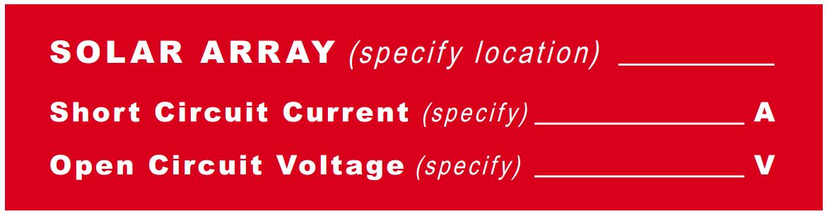
Fire Emergency Label is permanently fixed next to the meter box and main switchboard.
-
Is the Fire Emergency Label is permanently fixed next to the meter box and main switchboard.<br>SOLAR ARRAY ON ..(Location).. including correct Voc and Isc ratings
-
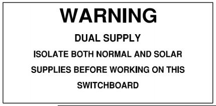
"WARNING DUAL SUPPLY ISOLATE BOTH NORMAL AND SOLAR SUPPLIES BEFORE WORKING ON THIS SWITCHBOARD" is located on the switchboard.
-
Is the "WARNING DUAL SUPPLY ISOLATE BOTH NORMAL AND SOLAR SUPPLIES BEFORE WORKING ON THIS SWITCHBOARD" is located on the switchboard.
-
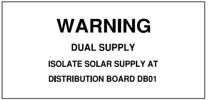
If the PV System is connected to a Distribution Board, the Main Switchboard and all other DB's are signed with "WARNING DUAL SUPPLY, ISOLATE SOLAR SUPPLY AT DISTRIBUTION BOARD ...XXX"
-
If the PV System is connected to a Distribution Board, the Main Switchboard and all other DB's are signed with "WARNING DUAL SUPPLY, ISOLATE SOLAR SUPPLY AT DISTRIBUTION BOARD ...XXX"
-
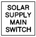
The AC Solar circuit breaker inside the switchboard is labelled "SOLAR SUPPLY MAIN SWITCH" or similar
-
Is the AC Solar circuit breaker inside the switchboard is labelled "SOLAR SUPPLY MAIN SWITCH" or similar
-
The AC Main Switch circuit breaker inside the switchboard is labelled "NORMAL SUPPLY MAIN SWITCH "
-
The AC Main Switch circuit breaker inside the switchboard is labelled "NORMAL SUPPLY MAIN SWITCH " or similar
-
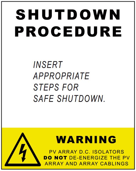
Shut Down procedure is correct and is permanently fixed at the inverter and/or switchboard
-
Is the Shut Down procedure is correct and is permanently fixed at the inverter and/or switchboard
-
The DC Isolators are signed "PV Array DC Isolator" or similar
-
The DC Isolators are signed "PV Array DC Isolator" or similar, (wording must align as specified on the Shut Down Procedure)
-
PV Array Junction Boxes are labelled "WARNING: HAZARDOUS DC VOLTAGE"
-
Any PV Array Junction Boxes are labelled "WARNING: HAZARDOUS DC VOLTAGE"
-
All PV cabling or conduit work clearly labelled as "SOLAR DC" every 2 mtrs, supported and secured
-
Provide any additional Information if any labels are found to be missing.
-
Photos of any issues identified above

DOCUMENTATION
-
Has the owner of the system been provided with a System Documentation folder in accordance with AS/NZS 5033 and AS/NZS 4777?
-
List any Issues identified regarding the documentation
-
Photos of any issues identified above
Finalisation
-
ALL photos taken during the Inspection including an issues identified have been uploaded to the Shared DropBox folder.
-
Additional information if required.
-
If the System has been deemed to be SAFE, Re-energise and leave ON
-
Rate the Outcome of the PV System Inspection
-
Any Additional photos to support this solar inspection?


