


Title Page
-
2 and 4 Yearly Cryogenic Vessel Inspection
-
Customer:
-
Customer Address:
-
Location:
-
Vessel number:
-
Vessel Contents:
-
Vessel Capacity:
-
Manufacturer:
-
Serial Number:
-
Coregas WO no:
-
Date of inspection:
-
Technician (Name):
-
Signature:
Vessel Inspection
-
Notes: The inspection frequency is 24 monthly except where indicated. Make good any deficiencies where practical. Checklist carried out in accordance with AS2896, AS1210, AS1894, AS1319, AS4332, AS1271, AS3788
INSPECTION ELEMENT
-
1. Record the Vessel Pressure upon arrival (kPa): If this is the normal operating pressure, upon completion of the inspection the vessel pressure should be returned to this.
-
2. Paintwork is in an acceptable condition<br><br>- Free from cracking, fading or chalkiness.<br>- Free of mould or algae growth<br>- Repainting is not required.
-
3. General cleanliness of the vessel is acceptable<br><br>- Free from contamination on the vessel or in couplings and connections.<br>- Major cleaning is not required/recommended (consider whether cleaning would be practical/effective vs repainting)<br>- Perform minor wash if required and practical.
-
Was the vessel washed during this inspection visit
- Not at all
- Fully
- Partially - nothing further required
- Partially - still needs further cleaning
-
4. General cleanliness of the compound is acceptable (refer to AS1894)<br><br>- Free from rubbish, organic matter, chemical contamination, combustible materials, other Dangerous Goods, moss build up on the ground, items or equipment that are not part of the installation.
-
5. General vessel condition is acceptable: Outer vessel and pipework (refer to AS3788 Section 4.4 and Appendix D)<br><br>- Free of damage or deterioration beyond normal wear and tear<br>- Free of cold spots or sweating<br>- Check outer vessel shell, pipework, valves, support legs and feet, transport legs, brackets and attachments, hold down bolts/clamps. <br>- No visible cracks in welds. Closely check all accessible welds, particularly structural welds (eg. legs to shell) and pipe penetrations through outer vessel
-
6. Corrosion is absent or not excessive. <br><br>- Check 360° around vessel, under vessel, on top of vessel where possible (look for nearby vantage points such as building roofs)<br>- Check behind data plates. Check condition of sealant where used around surface mounted data plates.<br>- Check behind and all around vessel legs<br>- Doubler pads should have weep holes sealed
-
7. Vessel logo is present and in good condition<br><br>- Note whether front and back logos are fitted.<br>- Note whether Logo is visible from primary external viewing locations (eg. visible from nearest passing traffic or site entrance/access)
-
8. Product label is present and legible<br>(Liquid Nitrogen, Liquid Oxygen, Liquid Argon, Liquid Carbon Dioxide, etc)
-
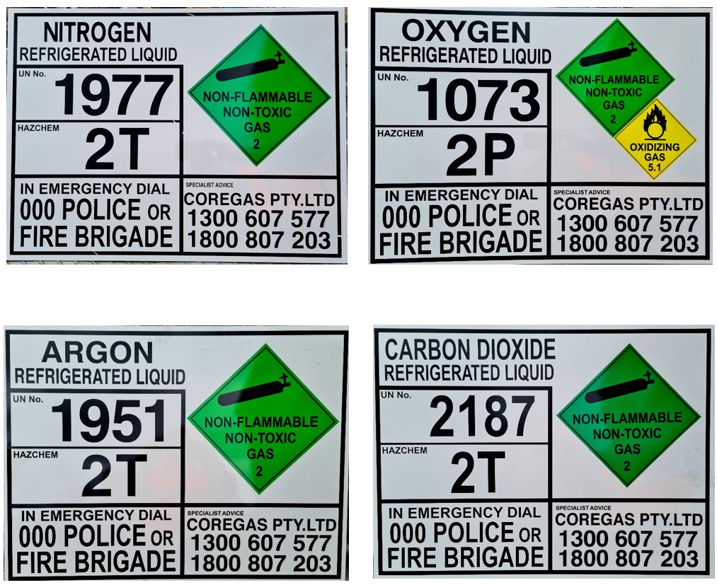
9. Dangerous Goods signs (Emergency Information Panel) present, correct, good condition.<br>Refer to ADGC and attachment below for correct details<br>
-
-
10. Emergency phone numbers are present, correct and legible on the EIP<br>Emergency – 1300 607 577<br>Business Hrs – 1800 807 203<br>
-
11. HAZCHEM and Warning signage is present and correct<br><br>- "HAZCHEM" in 100mm high red letters on white or silver background (at every site entrance where Emergency Services may enter). Site Owner responsibility.<br>- "WARNING: RESTRICTED AREA, AUTHORIZED PERSONEL ONLY"<br>- "DANGER: NO SMOKING, NO FLAME" (For oxygen installations)
-
12. Safety Signage present where applicable<br><br>Eg. "No Smoking No Naked Flames" (around Oxygen). <br>Oxygen deficiency hazard for inert gases in poorly ventilated/indoor spaces <br>
-
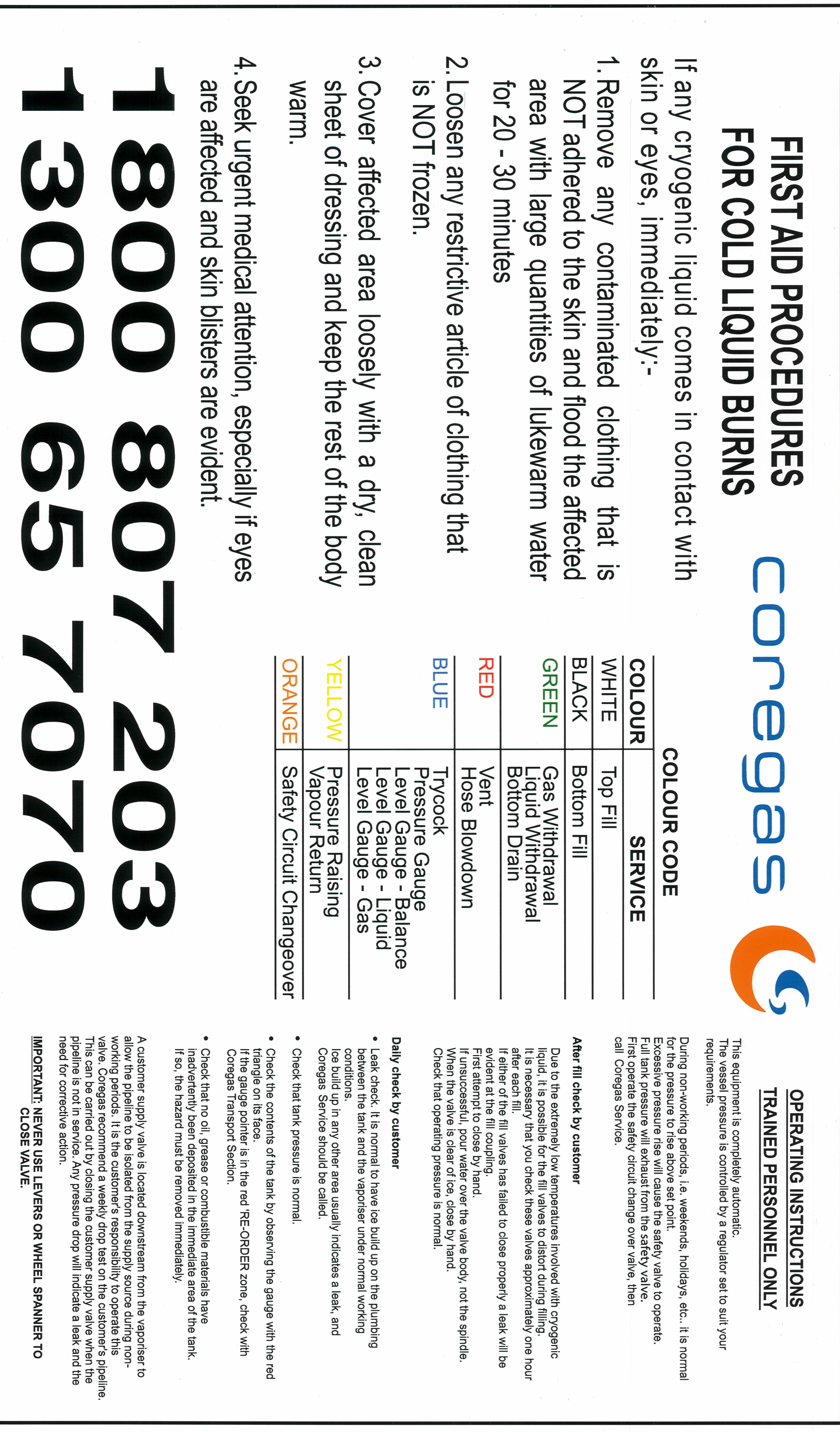
13. Vessel First Aid and Operating Instructions are present<br><br>- Refer to attachment below for correct details. <br>- Note that the last paragraph on the label must be removed or covered for medical or critical supply customers as it refers to isolation of supply (which should not be permitted).
-
-
14. Piping schematic is present, correct, and matches the actual piping configuration.<br><br>If not present, check that any proposed generic schematic label matches actual piping configuration before attaching. Otherwise, markup and forward to Tech Services at Yennora for action.<br>
-
15. Contents chart is present and tables the correct product
-
16. Vessel data plate is present and legible<br><br>- Critical information is present and legible (ie. Manufacturer, Serial Number, MAWP, Test Pressure, Manufacture or Hydro Test Date
-
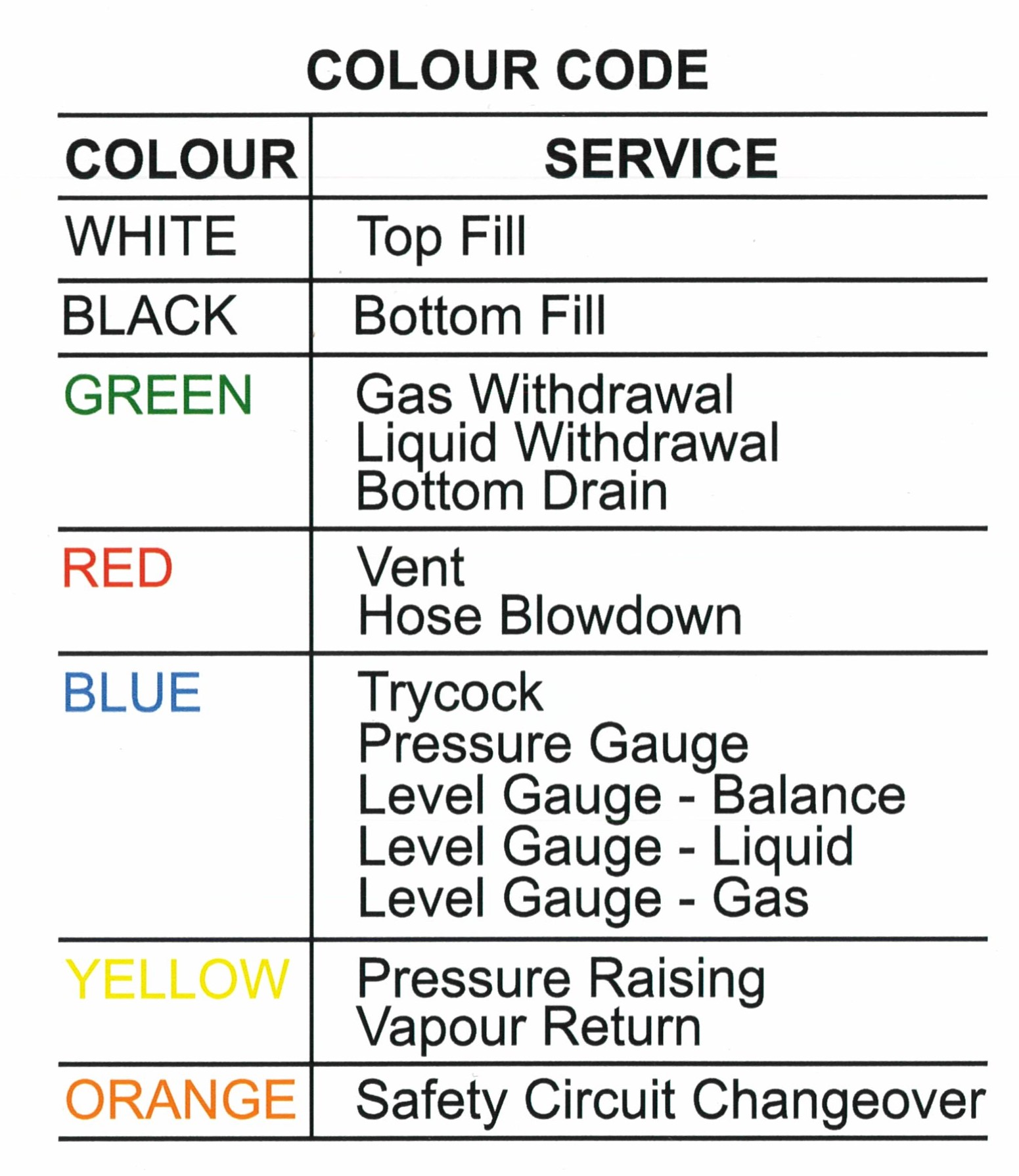
17. Valve hand-wheels are colour coded correctly<br><br>- Paint if missing / repaint if faded or incorrect. <br>- Refer to above ‘Operating Instructions” Label for correct colours<br>
-
-
18. Valves tags are present and correct (match the schematic)<br><br>- Cross check against schematic. Replace as required.
-
19. All Valves operate properly and shut tight.<br><br>- Test/check all valves for smooth operation and tightness/leaks where possible<br>- Note any valves not checked
-
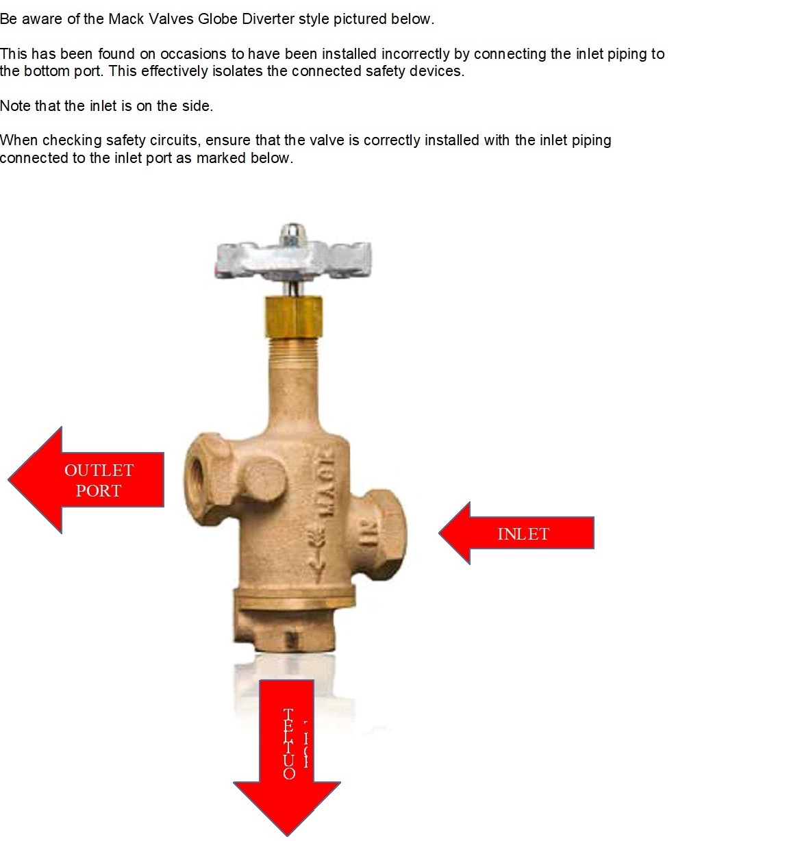
20. Safety circuit 3-way valve is operable and piped correctly. <br><br>- Check flow indicators where fitted. <br>- Ensure that the line to the vessel is connected to the marked Inlet.<br>- Pay Particular attention to Mack Valves Globe style with 2 outlets (refer to attachment for correct plumbing)<br>- Note any Ball Diverters with end connections (rather than top and bottom). Gather details and photos of the diverter model and Report back to Technical Services Engineering for review.<br>
-
-
-
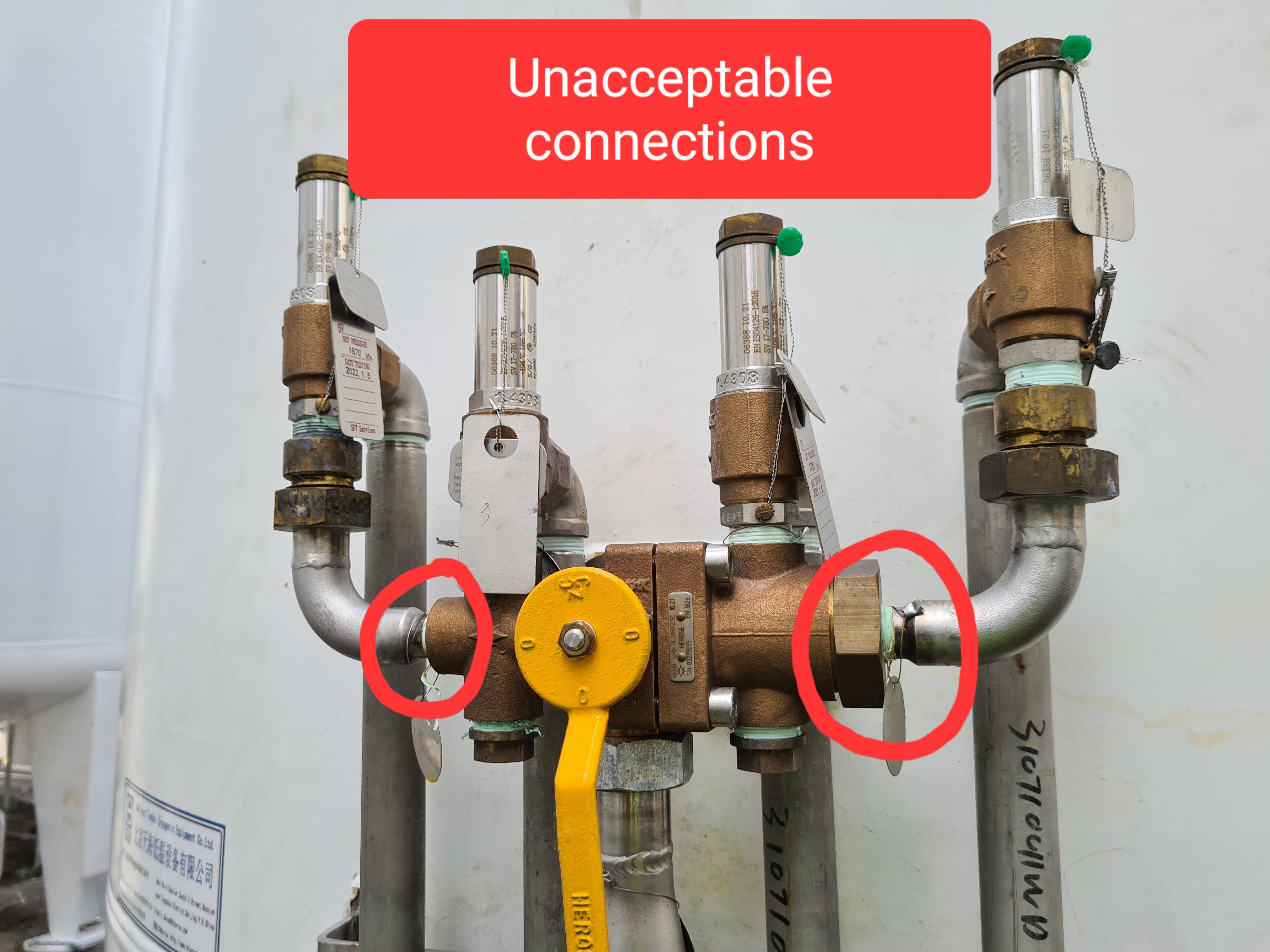
21. Safety valves are installed correctly.<br><br>- mounted upright with the thread connection at the bottom.<br>- fitted with correct flow directing elbows, braced and mounted in a way that cannot cause rotation when discharging. <br>- Be aware of screwed elbows and joiners on inlets. Discharging gas may cause rotation of elbows.<br>- The outlet of safety valves must be in line with any inlet elbow. <br>- Any discharge elbow must direct discharge vertically downwards<br>- Discharge does not impinge on other valves, jacket, or structural component (eg. Vessel Leg)<br>
-
22. Safety valves are in test (within 4 years of last test) and tagged with correct operating pressure.<br><br>- Verify pressure against MAWP on Vessel Data Plate<br>- Primary Safety valves set pressure is at or below the vessel design pressure (MAWP) <br>- Secondary safety valve set pressure is no more than 10% higher than the MAWP. This may be set the same as the Primary.<br>
Record Existing Safety Valve Details
-
Make and Model
-
Inlet Thread Size and Type
-
Tag No.
-
Serial No.
-
Set Pressure
-
Last Test Date
-
23. Evacuation valve outlet is sealed/wired<br><br>- Take a photo of the evacuation connection to aid future maintenance preparation.
-
24. Pressure gauge is safety pattern type and is suitable for industrial gas service<br><br>- Has the words “Oxygen” and “Use no oil”<br>- Has the words “Safety Pattern” printed on the face<br>- Blow out panel in rear of casing or <br>- Blow out back<br>- Must not be clamped/bracketed across the back if this obstructs the blow out panel<br>- If in doubt, take detailed photos of all sides and printed information for review by TS Manager
-
25. Pressure gauge operates correctly<br><br>- Cross check reading with telemetry<br>- Check for needle movement when increasing/decreasing vessel pressure
-
26. Pressure gauge is marked with Working Pressure and Safety Valve Set Pressure<br><br>- Check that these match Actual Safety Valve set pressure and PB regulator set pressure
-
27. Contents gauge is marked with full and reorder points. Check that Alarm contact switch is at the reorder point for Oxygen Vessels installed at Hospitals.<br><br>- Cross check against contents chart for mmWC at Trycock<br>- Re-Order should be at 50% of Full
-
28. Liquid relief valves are fitted and set at an appropriate pressure, between any liquid line valves and/or Non-Return Valves, which may trap liquid if closed.<br><br>- Set pressure must be appropriate for the line<br>- Class 150 flanges (where fitted) - line relief valves set to 1,900 kPa or lower<br>- Copper Type M: 1” dia. x 0.89mm wall thickness (WT) = 2,300 kPa (maximum)<br>- Copper Type L: 1” dia. x 1.27mm (WT) = 3,400 kPa (maximum)<br>- Copper Type K: 1”dia. x 1.65mm (WT) = 4,500 kPa (maximum)<br>- Copper Type M: 1.5” dia. x 1.25mm (WT) = 2,280 kPa (maximum)<br>- Copper Type L: 1.5” dia x 1.52mm (WT) = 2,800 kPa (maximum)<br>- Copper Type K: 1.5” dia. x 1.83mm (WT) = 3,400 kPa (maximum)<br>- S/S Tube & Pipe: For Cryogenic vessel systems = up to 5,000 kPa (nominally)
-
Tag No.
-
Line / Location:
-
Set Pressure
-
Last Test Date
-
29. Filling connection (incl. threads and seals) is in good condition and fitted with protection cap<br><br>- Note whether there is any evidence that the cap is being used (or not).
-
30. Pressure raising circuit is operating correctly.<br><br>- Where practical, verify correct operation by venting pressure and then checking for flow through PBC, and noting when flow stops & pressure stabilises.
-
Verified Set Pressure =
-
Apparent Set Pressure =
-
31. Top Fill and Bottom Fill isolation valves / Pressure Build isolation (yellow hand wheel) are open.
-
32. Ambient air vaporiser and pressure build coil are in good condition and not covered in excessive ice. Fan forced vaporiser (if installed) is operating correctly.<br><br>- Check for signs of damage, support cracking, foundation deterioration.<br>- Check all support brackets and bolts are secure
-
33. Check all valves and pipework for leaks with approved Leak Detection Fluid (LDF)<br><br>- Ensure lines being tested are under pressure - preferably normal vessel operating pressure<br>- Only compatible LDF is to be used and flushed with clean water after use<br>- Suitable products include:<br> • Snoop (Swagelok), VFV Leak Detector (Victoria Valves and Fittings), Sherlock Leak Detector, Big Blue Leak Detector
-
34. Telemetry unit is in an acceptable physical condition
-
35. Telemetry display is working and values are correct (the display updates when FILL button pressed).<br><br>- Cross check against analogue gauges (pressure and level) and Contents Chart
-
36. Confirm that there is no moisture inside the telemetry unit cover (external visual check only - do not remove cover unless necessary).
-
37. Conduit to telemetry unit and/or Level gauge is free of cracks and in good condition.
-
38. Other Conduit and wiring are all in good condition.
-
39. Line safety valve(s) are fitted after each vaporiser<br><br>- Note size / make / model<br>- Note whether a 3 way valve and standby safety valve are fitted to allow offline exchange.
-
Vaporiser Size
-
SV Make, Model, Size
-
SV ID & Serial No.
-
Set Pressure
-
Last Test Date
-
40. Down pressure regulator (if fitted) is in good condition and operating correctly.<br><br>- Where practical, test operation<br> - If the regulator is currently venting, vent vessel pressure further and note closure pressure<br> - If vessel pressure is lower than Reg. set pressure, increase vessel pressure (if practical) or remove and check function with cylinder gas source.<br>- Ensure it seals fully when pressure is reduced below setpoint
-
Verified Set pressure =
-
41. Replace top and bottom fill valve seats
-
Valve brand
-
42. Is current vacuum reading acceptable<br><br>- If reading is above 100 mTorr (Perlite insulated only), pump down if possible<br>- For Microbulk vessels (MLI insulation) if vac reading is above 20 mTorr, notify TS Manager and pump down as far as possible (these vessels should operate at very low vacuums ideally less than 1 mTorr, so may require further attention).<br>- If a vacuum reading is 1000 mTorr (DV6 head) this suggests a serious leak, or a faulty gauge. Refer to TS Manager<br>- If this an Oxygen vessel reading above 1000 mTorr, DO NOT CONNECT A NON-OXYGEN COMPATIBLE VACUUM PUMP.
-
Vac reading (initial)
-
Vac reading after pump down
-
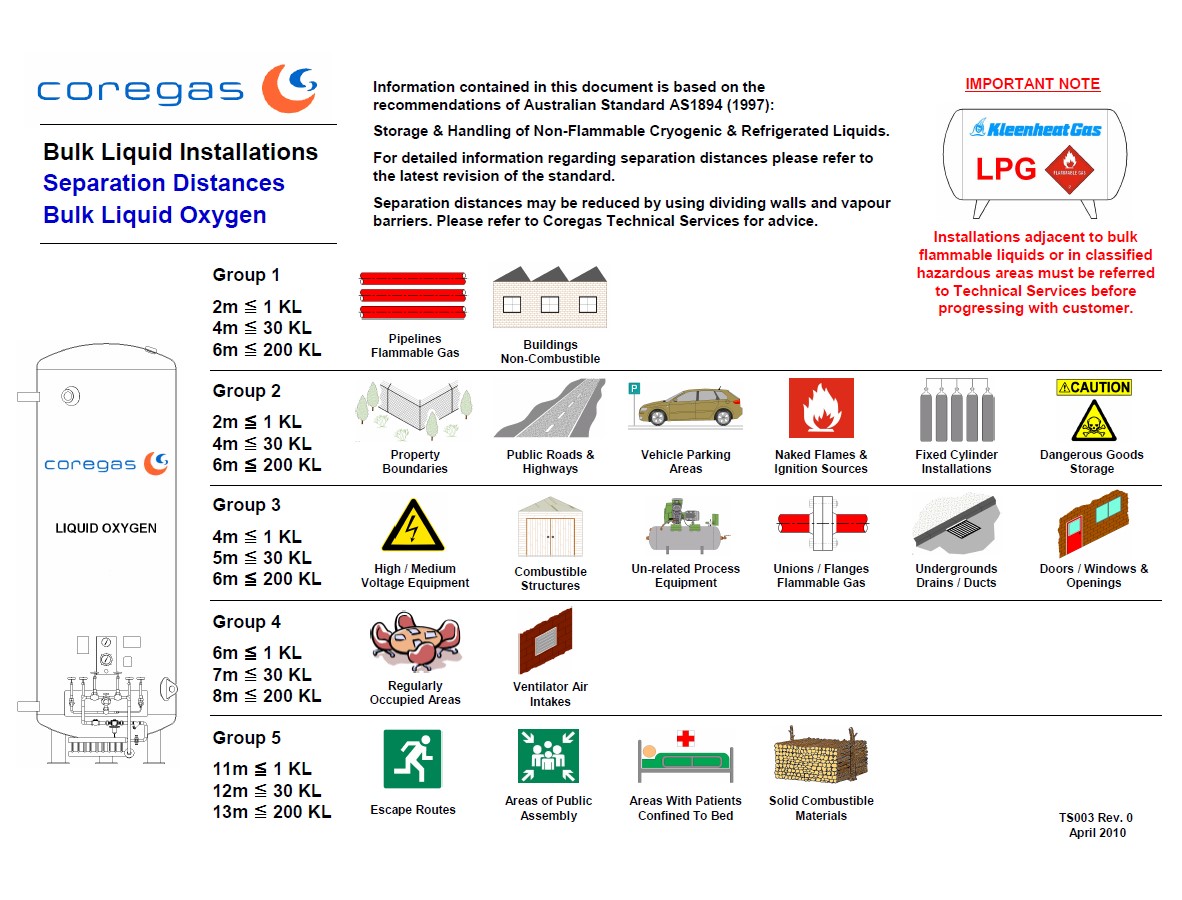
43. Separation distances for Oxygen are acceptable (refer to AS1894 Table 4.1)
-
-
44. Oxygen vessel – concrete hard stand (min 2.5m x 2.5m) with no filled expansion joints is in place (refer AS1894 Section 4.4)
-
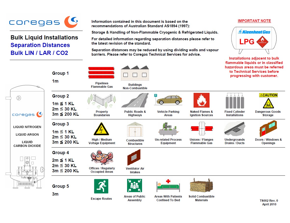
45. Separation distances for Inert Gases are acceptable (refer to AS1894 Table 5.1)
-
-
46. Bollards / impact protection is in place where required, is suitably rated, and is in good order (refer to AS1894 Section 3.5.2 and Appendix D)<br>
-
47. Condition of the vessel foundations and supports is acceptable (refer to AS3788 Appendix Z)<br><br>- Look for Subsidence, cracking, deterioration, exposure and/or corrosion of reinforcing.<br>- Check that Bolting to foundations is adequate and in good condition<br>- Check that vessel is plumb, and if there is any deviation, that it is not due to slab movement<br>- If a steel plate is used, check for excessive corrosion, slip hazards, bending or buckling<br>- Check vessel legs for corrosion, cracks, impact damage, bending
-
48. Ventilation is adequate for vessels in poorly ventilated areas or indoors (refer to AS1894 Section 3.5.4)<br><br>- Liquid Oxygen is not permitted in poorly ventilated areas or indoors.<br>- Forced ventilation is adequate and operating properly (10m3/min per 1200L approx vessel volume)<br>- Natural ventilation openings are adequate (10m2 in and 10m2 out per 1200L approx vessel volume)<br>- Oxygen deficiency meter is installed where appropriate, and is functioning.
-
49. Remote fill point (if fitted) allows line of sight to vessel gauges (refer to AS1894 Section 3.9.3), or if no line of sight, then vessel controls are duplicated (trycock, level and pressure gauges, top and bottom fill valves)
-
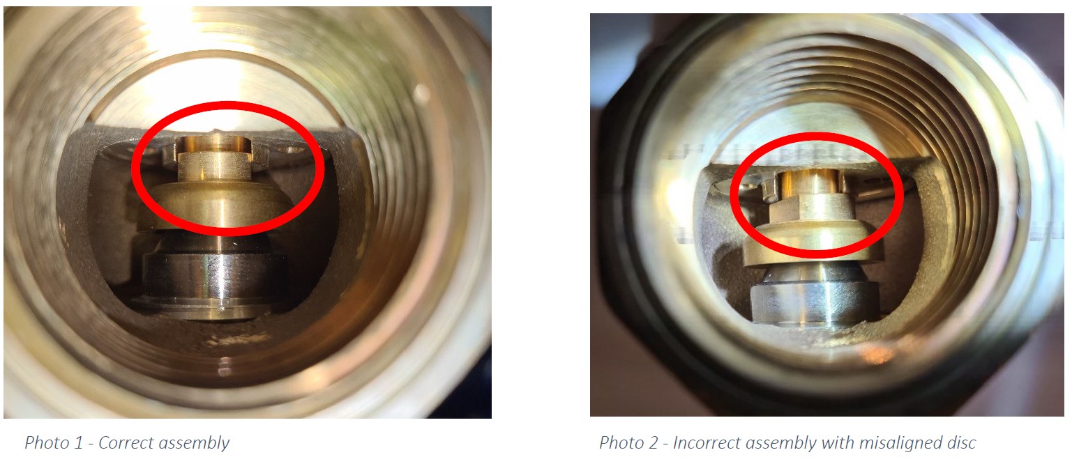
50. 24 monthly visual safety valve inspection as per SOP (CMS-10-SOP-9019) and AS3788 Section 4.7<br><br>- Lock wire Seal is in place<br>- Check for damage or deterioration. <br>- Check outlets for insect nests or other blockages.<br>- Herose safety valves – visually confirm that the disc is within the guides (refer images)<br>- Check bracing is adequate and does not allow for valve self-rotation<br>- If easing gear is fitted, lift and check for flow<br>- Check set pressure is correct (MAWP or lower).
-
51. Herose Safety Valves - is the disc stem is sitting within the disc-guide allowing proper function (refer images)<br><br>- If not, IMMEDIATELY NOTIFY TECHNICAL SERVICES MANAGER AND REPLACE COMPROMISED VALVES<br>- Non-functioning valves in this condition must be removed and sent to the Tech Services Manager for investigation - DO NOT RESET AND REUSE<br>- If replacement valves are not available, the vessel must be tagged Out Of Service and further instruction sought from the TS Manager
-
Herose Safety Valve disc alignment
4 Yearly Maintenance Tasks
-
52. Replace vessel thermal relief valves
Add New Line Relief Valve Details here
-
ID#
-
Set Pressure
-
Install Date
-
53. Replace line safeties after main supply vaporiser
Add New Vapouriser Safety Valve Details here
-
ID #
-
Make / Model / Size
-
Set Pressure
-
Install Date
-
54. Replace vessel main safety valves<br><br>- Existing Safety Valves are not to be retested in the field without prior approval from the TS Manager.<br>- If Field Testing is to be done, it must be by trained and Authorised technicians only, and must use approved and calibrated equipment to the standard operating procedure CMS-10-SOP-9019 and in accordance with AS3788 Section 4.7
Add New Vessel Safety Valve Details Here
-
ID#
-
Inlet Thread Size and Type
-
Make / Model
-
Serial #
-
Set Pressure
-
Are any Safety Valves being TESTED for Re-use on this vessel
Re-Tested Vessel Safety Valve Details (If applicable)
-
ID#
-
Make / Model
-
Inlet thread size / type
-
Lift Pressure (as tested)
-
Reseat Pressure (as tested)
-
Lift Pressure (as tested after adjustment)
-
Reseat Pressure (as tested after adjustment)
-
Status
-
Has the vessel pressure been returned to normal operating conditions?
-
Vessel pressure before leaving site (kPa)
New/Replacements Parts Installed
-
Asset Number
-
Component
-
Existing Component Serial No.
-
New Component Serial No.
-
Reason for Change out
-
Additional Comments
External Inspection Certification
-
I the undersigned, certify that I have performed an external inspection, including a visual inspection of the safety devices, in accordance with AS/NZS 3788 and the attached checklist, on the Cryogenic storage vessel detailed in the attached report and as detailed below
-
Vessel Manufacturer
-
MAWP
-
Serial Number
-
From the visual inspection undertaken, the vessel is
-
This Certificate shall, subject to the appropriate Regulations, remain in force for 4 years from the date of the inspection below. Any unauthorised or unexpected changes in the assessed conditions after this date, may render this certification invalid and subject to additional review.
-
Date:
-
Name:
-
Signature:
-
GENERAL REQUIREMENTS
This Certificate is cancelled when the Vessel is sold or dismantled for erection on another site.
The Vessel is to be operated only while maintained in a safe condition with its fittings in correct adjustment and, where necessary by Certified Persons.
The Identification Number is to be kept clean and distinct.
Next Inspection Date is based on Table 4.1 AS/NZS 3788


